CHIHAI GM25-370 AB Hall Encoder DC Gear Motor, 6V / 12V / 24V
CHIHAI GM25-370 AB Hall Encoder DC Gear Motor, 6V / 12V / 24V
CHIHAI MOTOR
Couldn't load pickup availability


Overview
The CHIHAI MOTOR CHR-GM25-370ABHL DC gear motor combines a 25mm metal gearbox with a brushed motor and AB quadrature Hall feedback. Choose a 6V, 12V or 24V winding, the required reduction ratio and a motor-only, mounting-bracket or 65mm wheel-kit package.
Features
- All-metal reduction gears, copper windings and a D-shaped output shaft.
- Two encoder channels provide pulse counting and direction information when decoded together.
- Ten standard reduction-ratio and no-load-speed choices, with actual availability shown by configuration.
- Wheel kits include one motor and one wheel; buy the required quantity for a multi-wheel vehicle.
Specifications
| Brand / model | CHIHAI MOTOR / CHR-GM25-370ABHL |
| Motor | 25mm-diameter brushed DC motor with all-metal reduction gears and AB Hall encoder |
| Voltage | Separate 6V, 12V and 24V windings; use only the voltage selected |
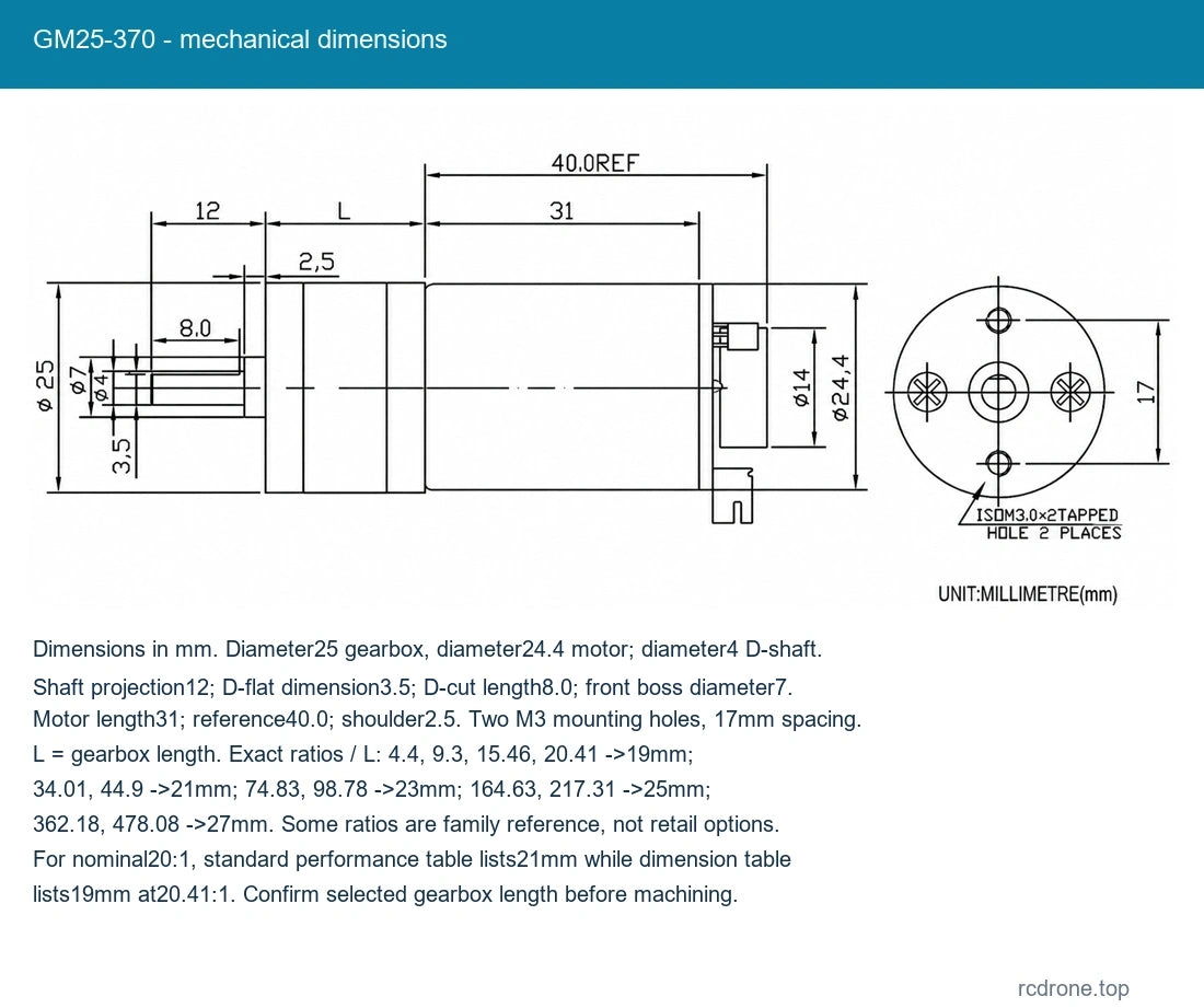
| Shaft | 4mm diameter D shaft; 12mm projection; D-cut section 8mm |
| Net mass reference | Approximately 100g motor; varies with reduction ratio and configuration |
| Motor body reference | 40mm reference dimension; gearbox length varies by reduction ratio |
| Gearbox length | 19mm for 4.4 and 9.3; 21mm for 20, 34 and 45; 23mm for 75 and 100; 25mm for 165 and 217; 27mm for 478 |
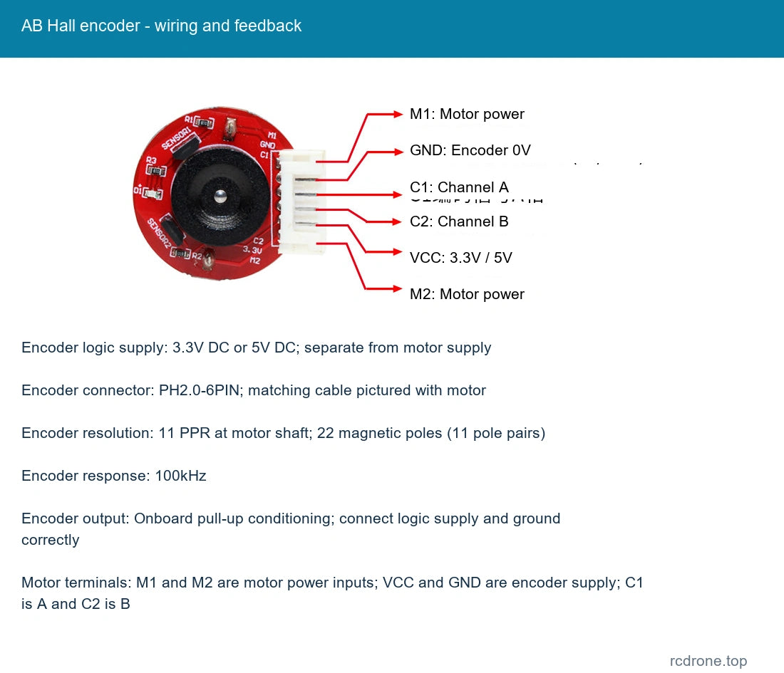
| Encoder | AB quadrature incremental magnetic Hall encoder, square-wave A/B |
| Encoder logic supply | 3.3V DC or 5V DC; separate from motor supply |
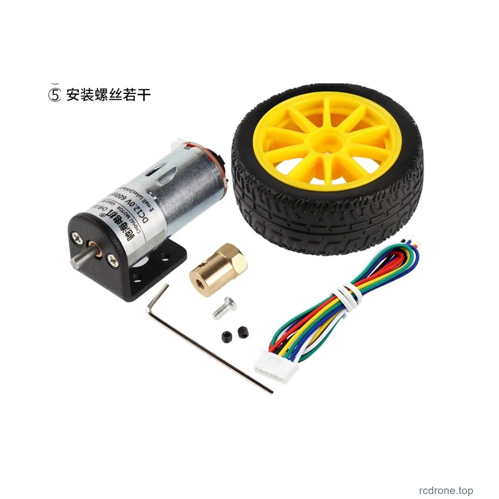
| Encoder connector | PH2.0-6PIN; matching cable pictured with motor |
| Encoder resolution | 11 PPR at motor shaft; 22 magnetic poles (11 pole pairs) |
| Encoder response | 100kHz |
| Encoder output | Onboard pull-up conditioning; connect logic supply and ground correctly |
| Motor terminals | M1 and M2 are motor power inputs; VCC and GND are encoder supply; C1 is A and C2 is B |
| Direction sensing | A/B phase order indicates direction. Counting one channel alone does not determine direction. |
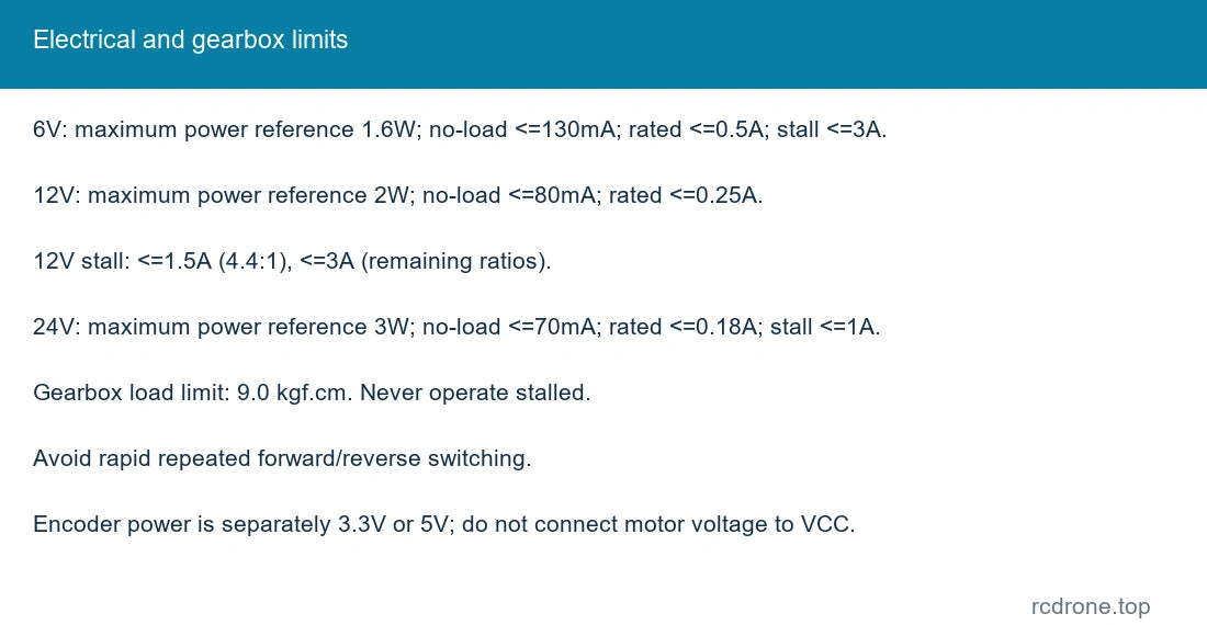
| Gearbox load limit | Do not exceed 9.0 kgf.cm load; avoid stall and repeated rapid direction reversal |
Standard-Winding Performance
Speeds below are no-load and rated reference points for the matching standard winding at its selected nominal voltage. Load reduces speed. Reduction-ratio names are rounded; the output encoder pulse figures use the more precise internal ratios. Pulse counts depend on the decoding mode and are not a four-edge count.
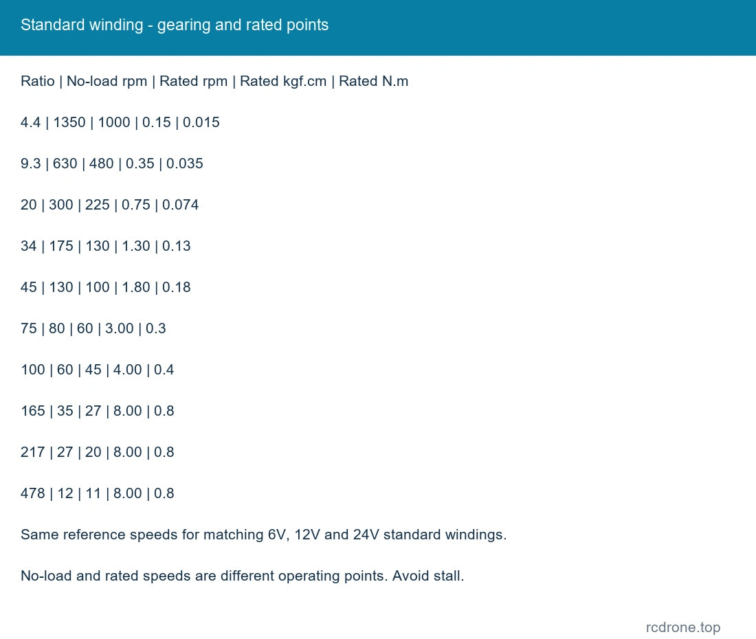
| Reduction :1 | No-load rpm | Rated rpm | Rated kgf.cm | Rated N.m | Output pulses/rev reference | Gearbox mm | Stall kgf.cm reference |
|---|---|---|---|---|---|---|---|
| 4.4 | 1350 | 1000 | 0.15 | 0.015 | 48.4 | 19 | 0.6 |
| 9.3 | 630 | 480 | 0.35 | 0.035 | 102.04 | 19 | 1.1 |
| 20 | 300 | 225 | 0.75 | 0.074 | 224.51 | 21 | 2.7 |
| 34 | 175 | 130 | 1.30 | 0.13 | 374.11 | 21 | 4.5 |
| 45 | 130 | 100 | 1.80 | 0.18 | 493.87 | 21 | 6.0 |
| 75 | 80 | 60 | 3.00 | 0.3 | 823.13 | 23 | 9.0 |
| 100 | 60 | 45 | 4.00 | 0.4 | 1086.58 | 23 | 9.0 limit |
| 165 | 35 | 27 | 8.00 | 0.8 | 1810.95 | 25 | 9.0 limit |
| 217 | 27 | 20 | 8.00 | 0.8 | 2390.43 | 25 | 9.0 limit |
| 478 | 12 | 11 | 8.00 | 0.8 | 5258.92 | 27 | 9.0 limit |
| Standard winding | Maximum power reference | No-load current | Rated current | Stall current reference |
|---|---|---|---|---|
| 6V standard winding | 1.6W | <=130mA | <=0.5A | <=3.0A |
| 12V standard winding | 2.0W | <=80mA | <=0.25A | <=1.5A for 4.4:1, <=3.0A for remaining ratios |
| 24V standard winding | 3.0W | <=70mA | <=0.18A | <=1.0A |
Stall values are reference limits, not operating conditions. Do not exceed 9.0 kgf.cm gearbox load, stall the motor or switch rapidly and repeatedly between forward and reverse.
Mechanical Dimensions
All dimensions are in mm. Gearbox diameter25; motor diameter24.4; output shaft diameter4, projection12, D-flat dimension3.5 and flat length8.0. Front boss diameter7, shoulder2.5, motor length31 and overall motor reference40.0. Two M3 mounting holes are spaced17mm. Gearbox length L varies by ratio. The dimension reference lists exact ratios 4.4/9.3/15.46/20.41 at19mm; 34.01/44.9 at21mm; 74.83/98.78 at23mm; 164.63/217.31 at25mm; 362.18/478.08 at27mm. Ratios15.46 and362.18 are family references rather than offered retail choices. For nominal20:1, the performance table lists21mm while the20.41:1 dimension reference lists19mm; confirm the selected gearbox length before machining.
Encoder Wiring and Use
M1 and M2 connect to motor power. Encoder VCC requires 3.3V or 5V, with GND as the logic ground. C1 is channel A and C2 is channel B. Do not apply the motor voltage to encoder VCC. The encoder has onboard pull-up conditioning for microcontroller connection. Decode A/B phase order for direction; a single pulse channel supplies counts but cannot distinguish forward from reverse.
Configuration Guide
The listed 6V, 12V and 24V motors are different windings, rather than a universal 6–24V motor. Select both nominal voltage and gearing. Undefined smart-car application windings requiring order remarks are not offered here. The standard 24V / 9.3:1 option was unavailable at capture.
Applications
Encoder-feedback wheel drives for small mobile robots and balancing-vehicle development, as well as compatible positioning, automation, camera mechanisms and compact cutting or paper-handling mechanisms. Match gearbox load, speed, duty cycle and controller to the mechanism. Robot, chassis, controller and power supply are not included.
What's Included
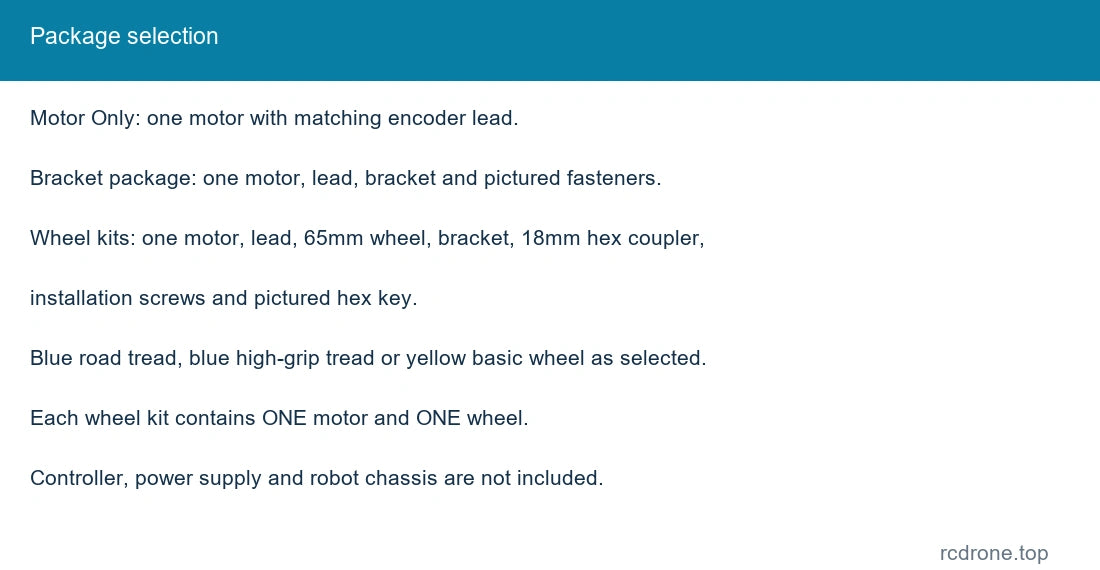
- Motor Only: one selected encoder gear motor and matching lead.
- Motor + Mounting Bracket: one motor, lead, bracket and pictured mounting fasteners.
- 65mm wheel kits: one motor and lead, one selected blue road-tread, blue high-grip or yellow basic 65mm wheel, one mounting bracket, one 18mm hex coupler, and pictured installation screws / hex key.
Alternative packages and optional accessories shown in comparison pictures are not all supplied together. No driver board or feedback controller is included.
Installation and Operation
- Confirm shaft dimensions, mounting holes, gearbox length and available clearance before fitting.
- Use only the selected nominal motor voltage. Encoder power is independently 3.3V or 5V.
- Check gearbox load and current demand before connecting a motor driver; avoid stall.
- For first power-up, run without load briefly and check direction and feedback before loading the mechanism.
- Avoid moisture, dust, heavy vibration and operation outside the required thermal conditions.
FAQ
Can the 12V motor be operated as a 24V version?
No. Select the winding intended for your motor supply; 6V, 12V and 24V versions are separate configurations.
Can the encoder be powered from the motor supply?
Encoder VCC requires 3.3V or 5V. Keep it separate from the motor voltage.
Is one encoder channel enough to detect direction?
No. Read both A and B and their phase relationship to determine rotation direction.
Does a wheel kit include a pair of wheels?
No. Each listed kit contains one motor and one selected 65mm wheel.
Visual Details