CHIHAI Magnetic Hall Motor Encoder Boards with Matching Magnet, 3–17 PPR
CHIHAI Magnetic Hall Motor Encoder Boards with Matching Magnet, 3–17 PPR
CHIHAI MOTOR
Couldn't load pickup availability


Overview
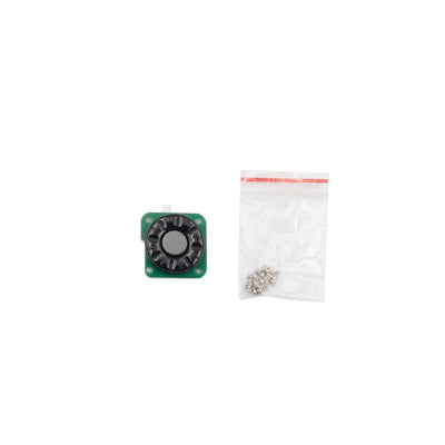
The CHIHAI MOTOR magnetic Hall encoder adds incremental two-channel shaft feedback to a matching motor installation. Choose the motor family, PPR, connector and lead arrangement from the actual configurations below. Each selection is an encoder accessory with a matching magnet; the motor is not included.
Features
- Magnetic sensing with two quadrature channels for rotation and direction feedback.
- Matching multipole magnet and board layout for the selected motor family.
- 3.3 V or 5 V Hall supply with illustrated pull-up/shaping resistors.
- PH2.0, XH2.54 and ZH1.5 connector arrangements, plus package-specific leads.
Specifications
| Product | Incremental magnetic Hall encoder board with matching multipole magnet; motor not included |
| Brand | CHIHAI MOTOR |
| Hall supply | 3.3 V DC or 5.0 V DC; separate from motor power |
| Output | Two-channel quadrature square-wave feedback; A/B or C1/C2 labels vary by board |
| Resolution | 3, 7, 11, 13 or 17 PPR as selected; base motor-shaft pulses, not the number of harness wires |
| Magnet poles | 6/14/22/26/34 alternating N/S poles for 3/7/11/13/17 PPR respectively |
| Counting | Controller edge-counting mode changes counted edges; gearbox output reference also depends on reduction ratio |
| Pull-up | Illustrated boards have pull-up/shaping resistors; match logic levels and controller inputs |
| 370 reference only | 25 mm board outline; approximately 2 g board+magnet excluding lead; 100 kHz response and −40 to +120 °C Hall-device reference, not a rating for every package |
Configuration Guide
| Motor fit family | PPR | Connector | Lead included | Arrangement | Magnet outer Ø mm | Magnet bore Ø mm |
|---|---|---|---|---|---|---|
| 370 | 11 | PH2.0 | 600 mm lead | Standard arrangement | 13.5 | 2 |
| 370 | 13 | PH2.0 | 600 mm lead | Standard arrangement | 13.5 | 2 |
| 370 | 11 | PH2.0 | No separate lead | Standard arrangement | 13.5 | 2 |
| 370 | 13 | PH2.0 | No separate lead | Standard arrangement | 13.5 | 2 |
| 260/280 | 11 | PH2.0 | No separate lead | Standard arrangement | 13.5 | 2 |
| 260/280 | 13 | PH2.0 | No separate lead | Standard arrangement | 13.5 | 2 |
| 520 | 11 | PH2.0 | No separate lead | Standard arrangement | 13.5 | 2 |
| 520 | 13 | PH2.0 | No separate lead | Standard arrangement | 13.5 | 2 |
| 520 | 11 | XH2.54 | No separate lead | Standard arrangement | 13.5 | 2 |
| 520 | 13 | XH2.54 | No separate lead | Standard arrangement | 13.5 | 2 |
| F130/F150/F180 | 11 | PH2.0 | No separate lead | Standard arrangement | 13.5 | 2 |
| F130/F150/F180 | 13 | PH2.0 | No separate lead | Standard arrangement | 13.5 | 2 |
| F130/F150/F180 | 11 | PH2.0 | 600 mm lead | Standard arrangement | 13.5 | 2 |
| F130/F150/F180 | 13 | PH2.0 | 600 mm lead | Standard arrangement | 13.5 | 2 |
| N20 | 7 | ZH1.5 | No separate lead | Standard arrangement | 9.2 | 1 |
| N20 | 3 | ZH1.5 | 100 mm lead | Standard arrangement | 9.4 | 1 |
| N20 | 7 | ZH1.5 | No separate lead | Side-solder arrangement | 9.2 | 1 |
| N20 | 7 | ZH1.5 | 40 mm lead | Side-solder arrangement | 9.2 | 1 |
| 030 | 7 | ZH1.5 | No separate lead | Standard arrangement | 9.2 | 1.5 |
| 050 | 7 | ZH1.5 | No separate lead | Standard arrangement | 9.2 | 1.5 |
| 360/380/390 | 17 | PH2.0 | No separate lead | Standard arrangement | 18 | 2.3 |
| 775 | 17 | PH2.0 | No separate lead | Standard arrangement | 18 | 5 |
| 545/555 | 17 | XH2.54 | No separate lead | Standard arrangement | 18 | 3.17 |
Magnet bores are identified as undersize-fit references; exact bore tolerances are not specified. Check the actual shaft, board mounting pattern, magnet clearance and connector before assembly. Family names do not establish universal fit across every motor bearing that number. The 775 option uses a 4-pin signal connector plus separate 2-pin motor terminals; it is not a six-pin signal board.
Connection Guide
The following sequences identify the illustrated terminal order, not a universal plug pin numbering standard. Match the actual board orientation and silk-screen labels. A/B and C1/C2 are the two feedback channels; confirm direction and counting convention in the receiving controller.
| Configuration | Illustrated signal / terminal reference |
|---|---|
| 370 with lead | M1 green; VCC blue; B white; A yellow; GND black; M2 red |
| 370 without lead | M1 / GND / B / A / VCC / M2 |
| 260/280 and 360/380/390 | M1 / GND / A / B / VCC / M2 |
| 520 | M1 / GND / B / A / VCC / M2 |
| F130/F150/F180 | M1 / GND / C2 / C1 / VCC / M2 |
| N20 7 PPR | M2 / VCC / C2 / C1 / GND / M1 |
| N20 3 PPR lead | M2 green; VCC blue; C2 white; C1 yellow; GND black; M1 red |
| N20 side-solder 40 mm lead | M2 red; VCC black; B yellow; A green; GND blue; M1 white |
| 030 / 050 | M2 / VCC / B / A / GND / M1 |
| 775 | PH2.0 4-pin signal: GND / C1 / C2 / VCC; separate VH3.96 2-pin motor power |
| 545/555 | M1 / GND / A / B / VCC / M2 |
Never apply motor supply voltage to the Hall VCC or signal outputs. Use the selected 3.3 V or 5 V Hall supply and a compatible logic interface. M1/M2 are motor connections, not encoder logic supply. For the 360/380/390, 775 and 545/555 high-power installation references, connect motor power directly to the motor solder terminals where appropriate, rather than routing high motor current through the small plug. Verify actual connector and conductor current capacity; no universal motor-current rating is specified.
Resolution and Installation
PPR refers to the base encoder/motor-shaft reference. Multiply by the actual gearbox reduction ratio for a gearbox-output pulse reference and account separately for x1/x2/x4 edge counting. An incremental encoder does not provide absolute shaft position after power-up.
Center the supplied magnet on the matching shaft and align it with the Hall sensors without contact. Check mounting clearance, magnet fit and stable signals before operation. Keep the board protected from shorts and mechanical damage. A motor controller, counter, gearbox and mounting mechanism are separate.
Applications
Speed feedback, relative rotation counting and direction detection in compatible motor-control, small robotics, balancing-platform and automation projects.
What's Included
One selected Hall encoder board and one matching magnetic disc. A separate lead is included only in configurations that explicitly name it; the 370 and F130 lead references are 600 mm, the N20 3 PPR lead is 100 mm, and the named N20 side-solder lead is 40 mm. Other connector versions show the board-mounted connector without a promised loose cable. No motor, power supply, controller or complete machine is included.
FAQ
Does “11 PPR” mean an eleven-wire cable?
No. It is the pulse-per-revolution reference, not the wire count.
Can I connect Hall VCC to my motor supply?
Use 3.3 V or 5 V for the Hall circuit. Motor voltage and encoder logic voltage are separate.
Does every configuration include a cable?
No. Select a configuration that explicitly names the lead and length you need.
Will it report an absolute shaft position?
No. It provides incremental quadrature feedback; absolute position requires a separate reference strategy.
Visual Details