Skip to product information
1 of 5

DFRobot SEN0142 MPU6050 6 DOF Gyroscope Accelerometer IMU Module with I2C Digital Motion Processor for Arduino & Robotics

DFRobot SEN0142 MPU6050 6 DOF Gyroscope Accelerometer IMU Module with I2C Digital Motion Processor for Arduino & Robotics

DFRobot

Regular price $25.00 USD
Regular price Sale price $25.00 USD
Sale Sold out
Taxes included. Shipping calculated at checkout.
View full details

Overview

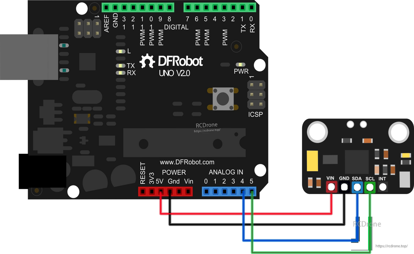
The DFRobot SEN0142 MPU6050 6 DOF IMU module integrates a 3-axis gyroscope and 3-axis accelerometer on a single chip, delivering accurate motion sensing for robotics, drones, wearable devices, and Arduino projects. Featuring a Digital Motion Processor (DMP), it supports advanced 6-axis and 9-axis MotionFusion algorithms, enabling quaternion, Euler angle, and raw sensor data output. With a wide input voltage range of 3V–5V, the MPU6050 can be directly connected to Arduino and other microcontrollers for real-time motion tracking and gesture detection.

Key Features

  • Combines 3-axis gyroscope and 3-axis accelerometer in one chip

  • Programmable accelerometer range: ±2g, ±4g, ±8g, ±16g

  • Gyroscope sensitivity: ±250, ±500, ±1000, ±2000 dps

  • Digital Motion Processor (DMP) for onboard MotionFusion and gesture recognition

  • I2C digital interface supports matrix, quaternion, Euler, and raw data formats

  • Embedded bias & compass calibration for improved accuracy

  • Compatible with Arduino and wearable electronics via I2Cdevlib

Specifications

  • Working Voltage: 3–5 V

  • Output: I2C digital (6/9-axis MotionFusion data)

  • Accelerometer: ±2g / ±4g / ±8g / ±16g programmable range

  • Gyroscope: ±250 / ±500 / ±1000 / ±2000 dps sensitivity

  • Data Format: Rotation matrix, quaternion, Euler angle, raw data

  • Dimensions: 14 × 21 mm

Applications

  • Robotics motion sensing

  • Arduino & DIY electronics projects

  • Human-Computer Interaction (HCI)

  • Wearable devices and gesture control

  • Navigation and balancing systems (e.g., Segway-type transporters)

  • Drone stabilization and motion tracking

Details

SEN0142 MPU6050 6 DOF Gyroscope Accelerometer IMU Module with I2C Digital Motion Processor for Arduino & Robotics

SEN0142 MPU6050 6 DOF Gyroscope Accelerometer IMU Module with I2C Digital Motion Processor for Arduino & Robotics

SEN0142 MPU6050 6 DOF Gyroscope Accelerometer IMU Module with I2C Digital Motion Processor for Arduino & Robotics


Sample Code

Please download the libraries for the all the IMU sensors first!

// I2C device class (I2Cdev) demonstration Arduino sketch for MPU6050 class
// 10/7/2011 by Jeff Rowberg <jeff@rowberg.net>
// Updates should (hopefully) always be available at https://github.com/jrowberg/i2cdevlib
//
// Changelog:
//      2013-05-08 - added multiple output formats
//                 - added seamless Fastwire support
//      2011-10-07 - initial release

/* ============================================
I2Cdev device library code is placed under the MIT license
Copyright (c) 2011 Jeff Rowberg
Permission is hereby granted, free of charge, to any person obtaining a copy
of this software and associated documentation files (the "Software"), to deal
in the Software without restriction, including without limitation the rights
to use, copy, modify, merge, publish, distribute, sublicense, and/or sell
copies of the Software, and to permit persons to whom the Software is
furnished to do so, subject to the following conditions:
The above copyright notice and this permission notice shall be included in
all copies or substantial portions of the Software.
THE SOFTWARE IS PROVIDED "AS IS", WITHOUT WARRANTY OF ANY KIND, EXPRESS OR
IMPLIED, INCLUDING BUT NOT LIMITED TO THE WARRANTIES OF MERCHANTABILITY,
FITNESS FOR A PARTICULAR PURPOSE AND NONINFRINGEMENT. IN NO EVENT SHALL THE
AUTHORS OR COPYRIGHT HOLDERS BE LIABLE FOR ANY CLAIM, DAMAGES OR OTHER
LIABILITY, WHETHER IN AN ACTION OF CONTRACT, TORT OR OTHERWISE, ARISING FROM,
OUT OF OR IN CONNECTION WITH THE SOFTWARE OR THE USE OR OTHER DEALINGS IN
THE SOFTWARE.
===============================================
*/

// I2Cdev and MPU6050 must be installed as libraries, or else the .cpp/.h files
// for both classes must be in the include path of your project
#include "I2Cdev.h"
#include "MPU6050.h"

// Arduino Wire library is required if I2Cdev I2CDEV_ARDUINO_WIRE implementation
// is used in I2Cdev.h
#if I2CDEV_IMPLEMENTATION == I2CDEV_ARDUINO_WIRE
    #include "Wire.h"
#endif

// class default I2C address is 0x68
// specific I2C addresses may be passed as a parameter here
// AD0 low = 0x68 (default for InvenSense evaluation board)
// AD0 high = 0x69
MPU6050 accelgyro;
//MPU6050 accelgyro(0x69); // <-- use for AD0 high
//MPU6050 accelgyro(0x68, &Wire1); // <-- use for AD0 low, but 2nd Wire (TWI/I2C) object

int16_t ax, ay, az;
int16_t gx, gy, gz;


// uncomment "OUTPUT_READABLE_ACCELGYRO" if you want to see a tab-separated
// list of the accel X/Y/Z and then gyro X/Y/Z values in decimal. Easy to read,
// not so easy to parse, and slow(er) over UART.
#define OUTPUT_READABLE_ACCELGYRO

// uncomment "OUTPUT_BINARY_ACCELGYRO" to send all 6 axes of data as 16-bit
// binary, one right after the other. This is very fast (as fast as possible
// without compression or data loss), and easy to parse, but impossible to read
// for a human.
//#define OUTPUT_BINARY_ACCELGYRO


#define LED_PIN 13
bool blinkState = false;

void setup() {
    // join I2C bus (I2Cdev library doesn't do this automatically)
    #if I2CDEV_IMPLEMENTATION == I2CDEV_ARDUINO_WIRE
        Wire.begin();
    #elif I2CDEV_IMPLEMENTATION == I2CDEV_BUILTIN_FASTWIRE
        Fastwire::setup(400, true);
    #endif

    // initialize serial communication
    // (38400 chosen because it works as well at 8MHz as it does at 16MHz, but
    // it's really up to you depending on your project)
    Serial.begin(38400);

    // initialize device
    Serial.println("Initializing I2C devices...");
    accelgyro.initialize();

    // verify connection
    Serial.println("Testing device connections...");
    Serial.println(accelgyro.testConnection() ? "MPU6050 connection successful" : "MPU6050 connection failed");

    // use the code below to change accel/gyro offset values
    /*
    Serial.println("Updating internal sensor offsets...");
    // -76	-2359	1688	0	0	0
    Serial.print(accelgyro.getXAccelOffset()); Serial.print("\t"); // -76
    Serial.print(accelgyro.getYAccelOffset()); Serial.print("\t"); // -2359
    Serial.print(accelgyro.getZAccelOffset()); Serial.print("\t"); // 1688
    Serial.print(accelgyro.getXGyroOffset()); Serial.print("\t"); // 0
    Serial.print(accelgyro.getYGyroOffset()); Serial.print("\t"); // 0
    Serial.print(accelgyro.getZGyroOffset()); Serial.print("\t"); // 0
    Serial.print("\n");
    accelgyro.setXGyroOffset(220);
    accelgyro.setYGyroOffset(76);
    accelgyro.setZGyroOffset(-85);
    Serial.print(accelgyro.getXAccelOffset()); Serial.print("\t"); // -76
    Serial.print(accelgyro.getYAccelOffset()); Serial.print("\t"); // -2359
    Serial.print(accelgyro.getZAccelOffset()); Serial.print("\t"); // 1688
    Serial.print(accelgyro.getXGyroOffset()); Serial.print("\t"); // 0
    Serial.print(accelgyro.getYGyroOffset()); Serial.print("\t"); // 0
    Serial.print(accelgyro.getZGyroOffset()); Serial.print("\t"); // 0
    Serial.print("\n");
    */

    // configure Arduino LED pin for output
    pinMode(LED_PIN, OUTPUT);
}

void loop() {
    // read raw accel/gyro measurements from device
    accelgyro.getMotion6(&ax, &ay, &az, &gx, &gy, &gz);

    // these methods (and a few others) are also available
    //accelgyro.getAcceleration(&ax, &ay, &az);
    //accelgyro.getRotation(&gx, &gy, &gz);

    #ifdef OUTPUT_READABLE_ACCELGYRO
        // display tab-separated accel/gyro x/y/z values
        Serial.print("a/g:\t");
        Serial.print(ax); Serial.print("\t");
        Serial.print(ay); Serial.print("\t");
        Serial.print(az); Serial.print("\t");
        Serial.print(gx); Serial.print("\t");
        Serial.print(gy); Serial.print("\t");
        Serial.println(gz);
    #endif

    #ifdef OUTPUT_BINARY_ACCELGYRO
        Serial.write((uint8_t)(ax >> 8)); Serial.write((uint8_t)(ax & 0xFF));
        Serial.write((uint8_t)(ay >> 8)); Serial.write((uint8_t)(ay & 0xFF));
        Serial.write((uint8_t)(az >> 8)); Serial.write((uint8_t)(az & 0xFF));
        Serial.write((uint8_t)(gx >> 8)); Serial.write((uint8_t)(gx & 0xFF));
        Serial.write((uint8_t)(gy >> 8)); Serial.write((uint8_t)(gy & 0xFF));
        Serial.write((uint8_t)(gz >> 8)); Serial.write((uint8_t)(gz & 0xFF));
    #endif

    // blink LED to indicate activity
    blinkState = !blinkState;
    digitalWrite(LED_PIN, blinkState);
    delay(100);
}