


JHEMCU F411ELVTX F411 AIO Flight Controller w/ 5.8G 400mW VTX, 12A ESC & 2.4G ELRS
JHEMCU F411ELVTX F411 AIO Flight Controller w/ 5.8G 400mW VTX, 12A ESC & 2.4G ELRS
JHEMCU
Couldn't load pickup availability


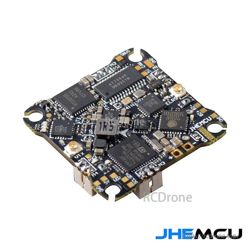
Overview
The JHEMCU F411ELVTX is an AIO (all-in-one) F411 flight controller board integrating a 5.8G 400mW analog VTX, a 12A 4-in-1 ESC, and a 2.4G ELRS receiver for compact FPV builds. It combines flight control, video transmission, motor drive, and ExpressLRS radio reception on a single PCB to reduce wiring and simplify installation.
Key Features
- Integrated 5.8G VTX with SmartAudio control ("TBS Smart Audio" shown)
- Integrated 2.4G ELRS receiver with onboard 2.4G antenna connection
- Integrated 12A 4-in-1 ESC
- Micro USB port
- Onboard boot keys: DFU BOOT key and ELRS BOOT key
- Status indicators shown: VTX status, power LED, FC status, receiver status LED
- Chips/ICs called out: STM32F411 MCU, AT7456E OSD chip, ICM-42688-P gyro/accelerometer, Epson crystal oscillator, ELRS RF chip, 5.8G transmission RF chip, power chip, GD32F130 (5.8G MCU), ESC MCU, current sensor
For wiring or setup assistance, contact [email protected] or visit https://rcdrone.top/.
Specifications
| Model | JHEMCU F411ELVTX |
| Flight controller MCU | STM32F411 |
| OSD chip | AT7456E |
| Gyro/accelerometer | ICM-42688-P |
| Integrated receiver | 2.4G ELRS (ELRS RF chip + ELRS ESP MCU shown) |
| Integrated VTX | 5.8G, up to 400mW (SmartAudio control shown) |
| ESC | 12A (board marking shows “12A”) |
| USB | Micro USB |
| Battery marking (as printed/diagrammed) | PCB marking shows “2-4S”; wiring diagram references “1-2S Lipo Battery” |
VTX Channel / Frequency Table (as shown)
| Band | CH1 | CH2 | CH3 | CH4 | CH5 | CH6 | CH7 | CH8 |
|---|---|---|---|---|---|---|---|---|
| BOSCAM_A | 5865 | 5845 | 5825 | 5805 | 5785 | 5765 | 5745 | 5725 |
| BOSCAM_B | 5733 | 5752 | 5771 | 5790 | 5809 | 5828 | 5847 | 5866 |
| BOSCAM_E | 5705 | 5685 | 5665 | 5645 | 5885 | 5905 | 5925 | 5945 |
| FATSHARK | 5740 | 5760 | 5780 | 5800 | 5820 | 5840 | 5860 | 5880 |
| RACEBAND | 5658 | 5695 | 5732 | 5769 | 5806 | 5843 | 5880 | 5917 |
| LOWRACE | 5333 | 5373 | 5413 | 5453 | 5493 | 5533 | 5573 | 5613 |
VTX Power Levels (as shown)
| Levels | 5 |
| Labels | 25 / 100 / 200 / 300 / 400 |
| Values | 14 / 20 / 23 / 25 / 26 |
Wiring / Pads Shown
- Camera pads shown: GND / 5V / VID
- LED pads shown: GND / +5V / LED
- UART pads shown: TX2 / RX2
- I2C pads shown: SDA / SCL
- Buzzer pads shown: BZ- / BZ+
- SBUS: SBUS short contact point shown, with note that external SBUS receiver wiring requires soldering two small pads (as illustrated)
Setup Notes Shown
- 5.8G 400mW VTX configuration screen note: enabling a switch can reduce AIO heating at low power when not unlocked; "Reduce image transmission power when not unlocked" text shown.
- ESC configuration screenshots (BLHeli_S and Bluejay) include a note: if using a 1S battery and the motor is difficult to start, increase the starting power to a value that starts the motor.
What's Included
- JHEMCU F411ELVTX AIO board
- 5.8G antenna (labeled “5.8G Antenna”)
- 2.4G ELRS antenna (labeled “2.4G ELRS antenna”)
- Red sleeves/caps (4 pieces shown)
Details
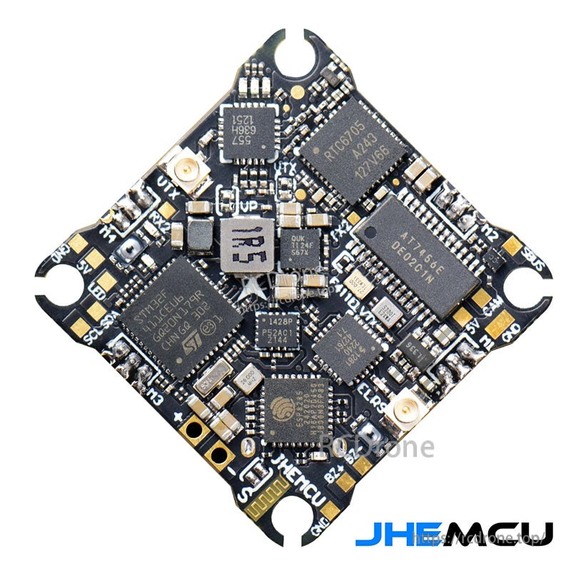
An all-in-one FPV stack that combines the F411 flight controller, 12A 4-in-1 ESC, 5.8GHz analog VTX, and 2.4GHz ELRS RX on a single board for compact builds.
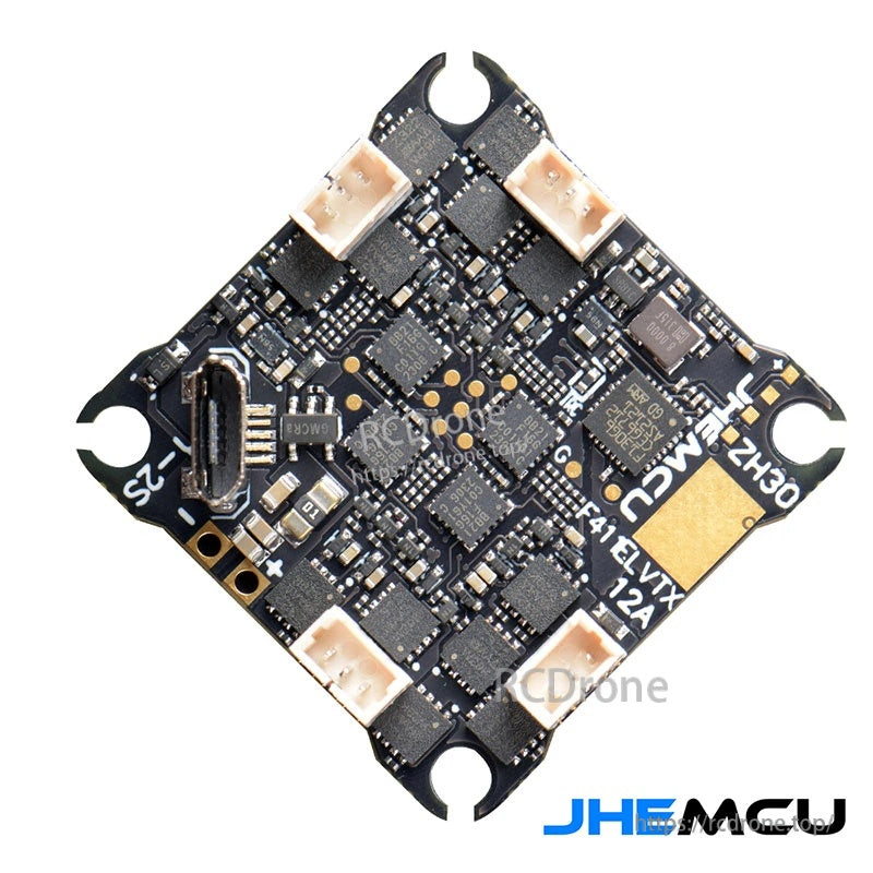
The underside layout keeps the ESC and power sections compact while providing easy access to the Micro USB for setup and firmware work.

Key chips and clearly labeled pads help simplify wiring for camera, video, and control signals on tight micro frames.
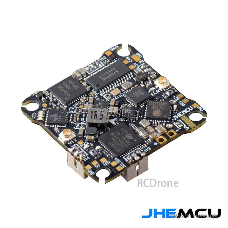
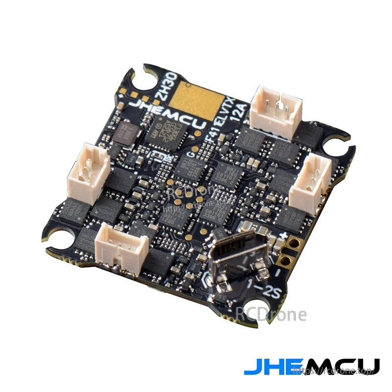
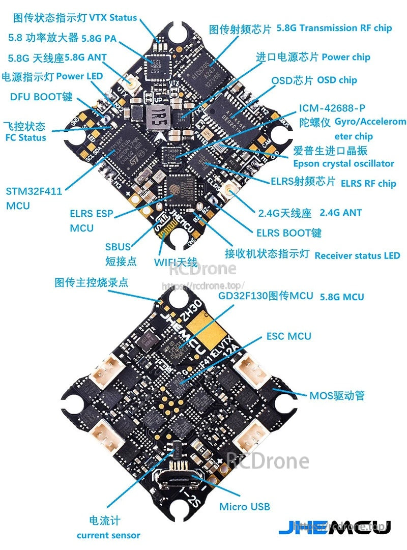
A labeled component map makes it easier to locate the MCU, OSD, gyro, VTX, and ELRS areas when troubleshooting or soldering.
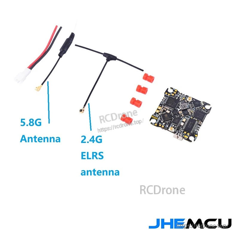
Both the 5.8GHz video antenna and the 2.4GHz ELRS antenna are included so the AIO can be installed and bound with minimal extras.
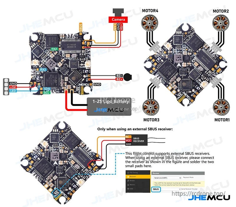
Wiring guidance covers camera power/video, motor outputs, battery leads, and optional external SBUS receiver bridging.
