


JHEMCU GHF745AIO-50A F745 AIO Flight Controller + 50A 32-Bit BLHeli-32 ESC for FPV Drone
JHEMCU GHF745AIO-50A F745 AIO Flight Controller + 50A 32-Bit BLHeli-32 ESC for FPV Drone
JHEMCU
Couldn't load pickup availability


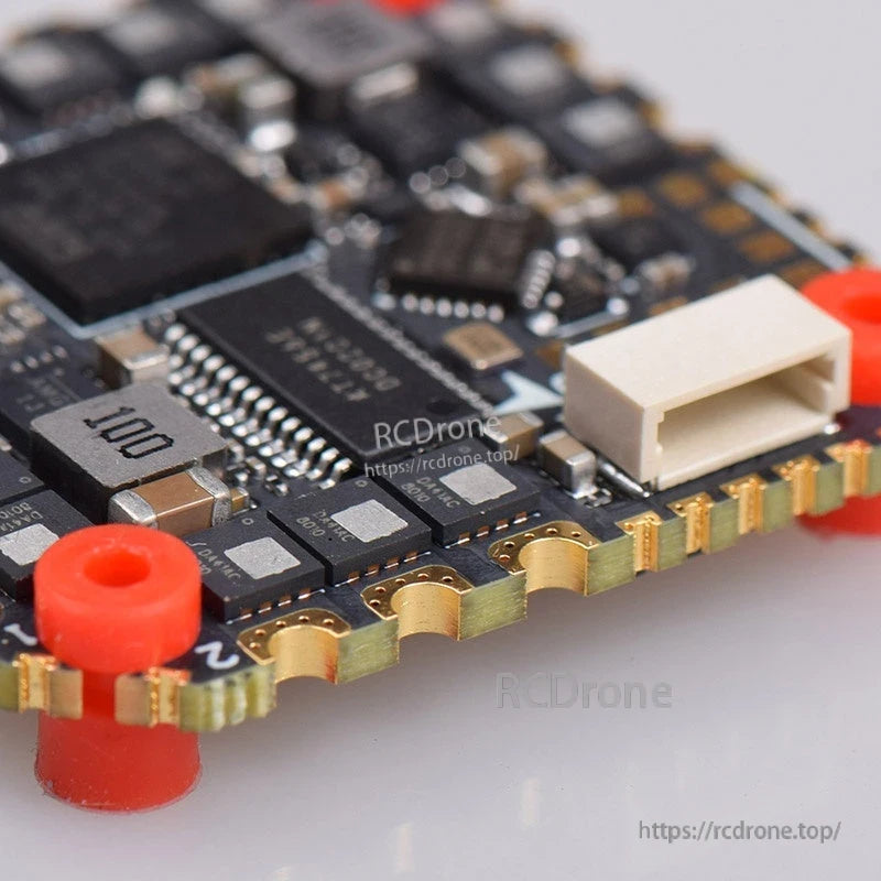
Overview
JHEMCU GHF745AIO-50A is an AIO flight controller that integrates an F745 flight controller and a 50A 32-bit ESC for FPV multirotor builds. The board includes onboard OSD, an 8MB blackbox, a Micro USB port, and dedicated pads/ports for common peripherals such as digital HD VTX, analog VTX, camera, GPS/magnetometer, LED and buzzer.
Key Features
- All-in-one design: F745 flight controller + 50A 32-bit ESC
- Flight controller MCU: STM32F745 (BGA)
- Gyro: MPU6000
- OSD chip onboard
- Blackbox: 8MB
- ESC MCU: STM32G071; BLHELI-32 BIT noted on the board diagram
- Power-related components called out: built-in TVS tube, current sensor, imported filter capacitor
- Ports/pads called out: HD interface / O3 port, Micro USB, DFU BOOT, LED, buzzer (BZ+/BZ-), GPS (with I2C SDA/SCL and UART)
- 10V output is labeled in the board callouts
- Wiring note: when using SBUS/IBUS/DSM receivers, enable UART2 as Serial RX
- 50A MOS version identified (comparison image also labels a 40A MOS version separately)
Specifications
| Model | GHF745AIO-50A |
| Brand | JHEMCU |
| Flight controller MCU | STM32F745 (BGA) |
| Gyro | MPU6000 |
| OSD | OSD chip onboard |
| Blackbox | 8MB |
| ESC | 50A, 32-bit |
| ESC MCU | STM32G071 |
| ESC firmware (noted) | BLHELI-32 BIT |
| Battery input (wiring diagram) | 2–6S LiPo |
| USB | Micro USB |
| Weight (shown) | 8.5 g |
What's Included
- JHEMCU GHF745AIO flight controller/ESC AIO board
- Electrolytic capacitor
- Wiring harnesses (as shown)
- XT60 connector (as shown)
- Red/black power wires (as shown)
- JHEMCU soldering practice board (as shown)
Wiring / Connections (Diagram Highlights)
- Motors: MOTOR1, MOTOR2, MOTOR3, MOTOR4 pads shown
- Battery: 2–6S LiPo battery connection shown, with capacitor across the input leads
- Receiver examples shown: CRSF, IBUS, DSM, SBUS (with a note to enable UART2 Serial RX for SBUS/IBUS/DSM)
- Digital HD VTX wiring example shown (pads labeled SBUS, TX, RX, GND, 7–26V, +10V)
- Analog 5.8GHz VTX wiring example shown (pads labeled 7–26V, GND, VIDEO, RX)
- Camera pads shown: GND, +5V, CAM
- GPS/magnetometer example shown: SDA, SCL, TX, RX, +5V, GND
For pre-purchase compatibility questions or wiring help, contact [email protected] or visit https://rcdrone.top/.
Details
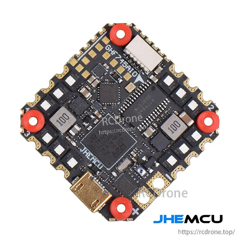
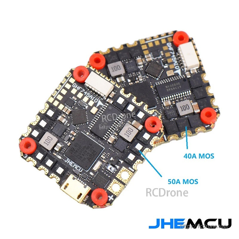
Choose the 50A MOS version for higher-current FPV builds while keeping the same compact all-in-one layout.
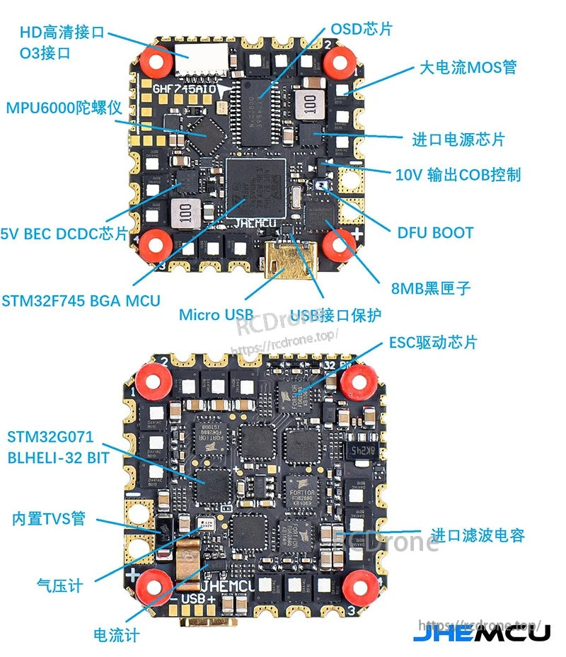
Integrated OSD, 8MB blackbox, Micro USB, and dedicated pads for HD VTX, analog video, GPS/I2C, LED, and buzzer simplify clean wiring.
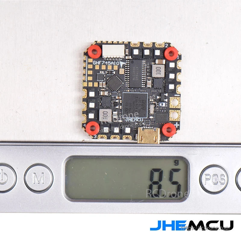
At about 8.5 g, the stack stays lightweight for tight FPV frames.
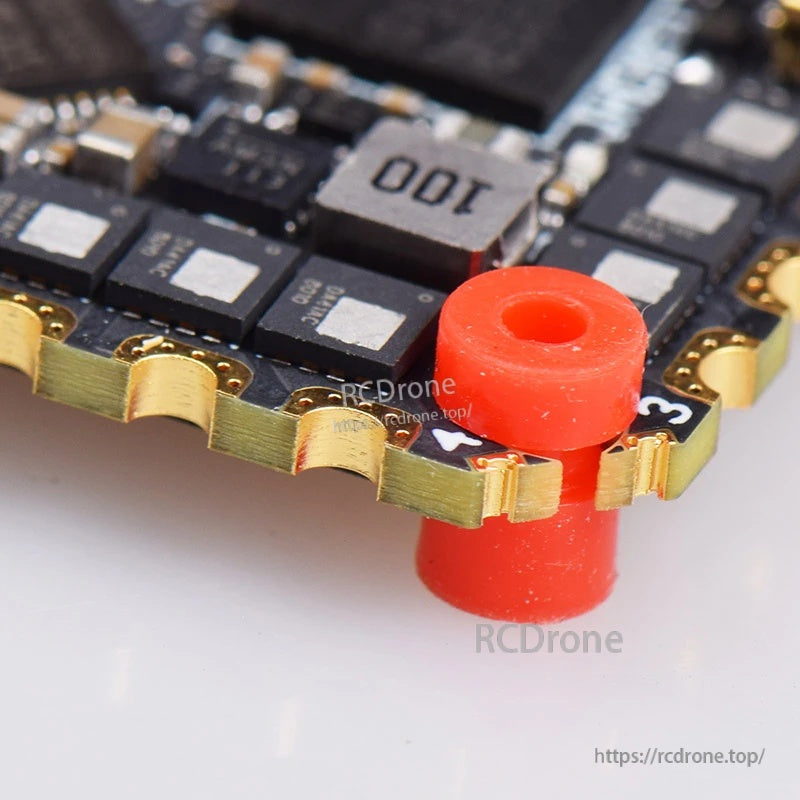
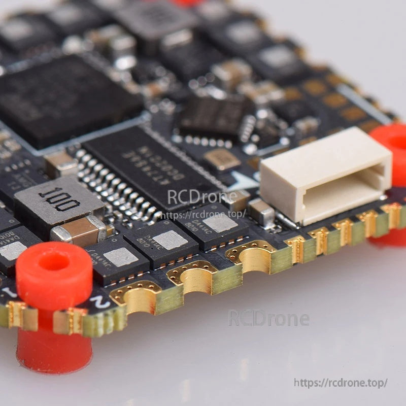
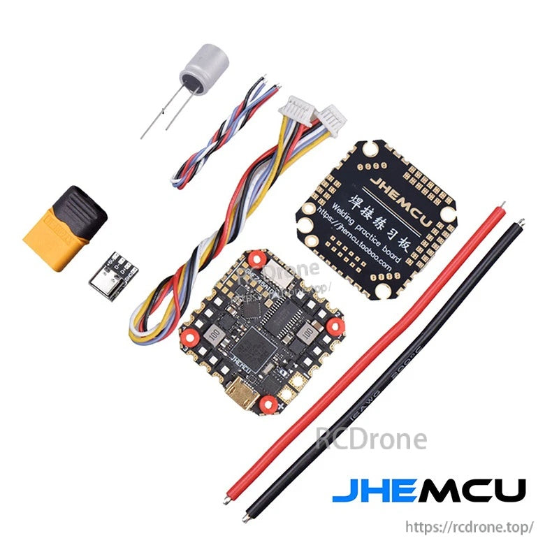
Included accessories cover power hookup, a filter capacitor, harness leads, and a practice solder board for easier first-time setup.
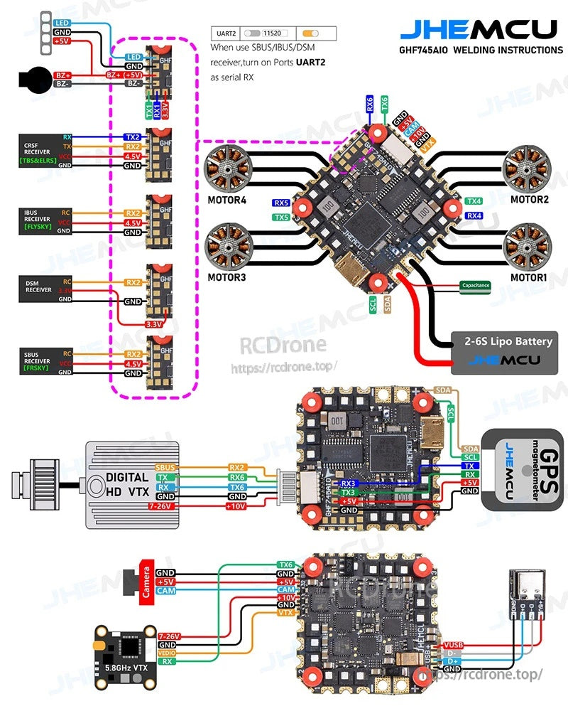
Clear wiring guidance for motors, 2–6S battery input, digital HD or analog VTX, camera, GPS, and common receiver protocols including SBUS/IBUS/DSM.