Jiuying MINIFZ14 Compact Harmonic Stepper Gearmotor – 30:1 to 100:1
Jiuying MINIFZ14 Compact Harmonic Stepper Gearmotor – 30:1 to 100:1
Jiuying
Couldn't load pickup availability


Overview
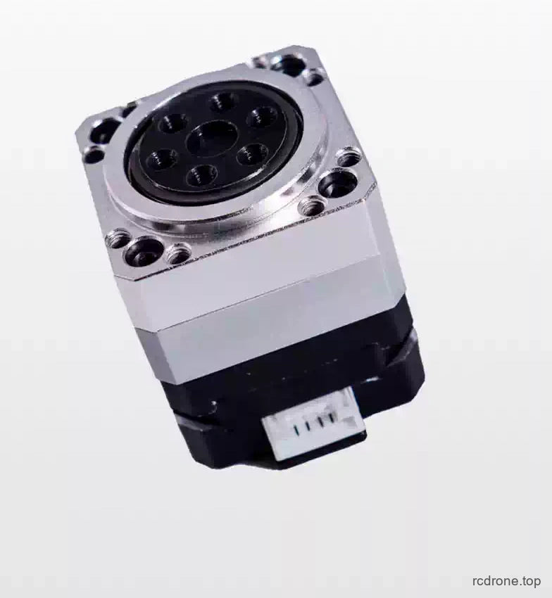
The Jiuying MINIFZ14 combines a compact harmonic reducer with a 42 mm stepper motor for controlled rotary motion in tight spaces. Its square mounting face, short axial profile and direct-coupled construction suit compact positioning mechanisms, small robot joints and custom motion assemblies.
Choose a 30:1, 50:1, 80:1 or 100:1 motor-and-reducer assembly. Each option includes the motor and harmonic reduction unit; a separate current-controlled stepper driver is required.
Features
- Integrated harmonic reduction and 42BYGH23 stepper motor in a compact assembly.
- Four reduction ratios let you balance output speed, positioning increment and recommended torque.
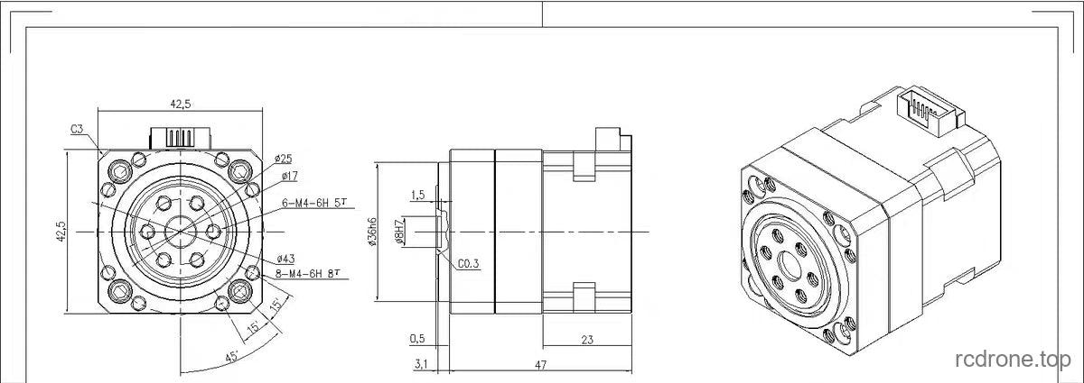
- 42.5 × 42.5 mm front face and 47 mm overall axial length in the assembly drawing.
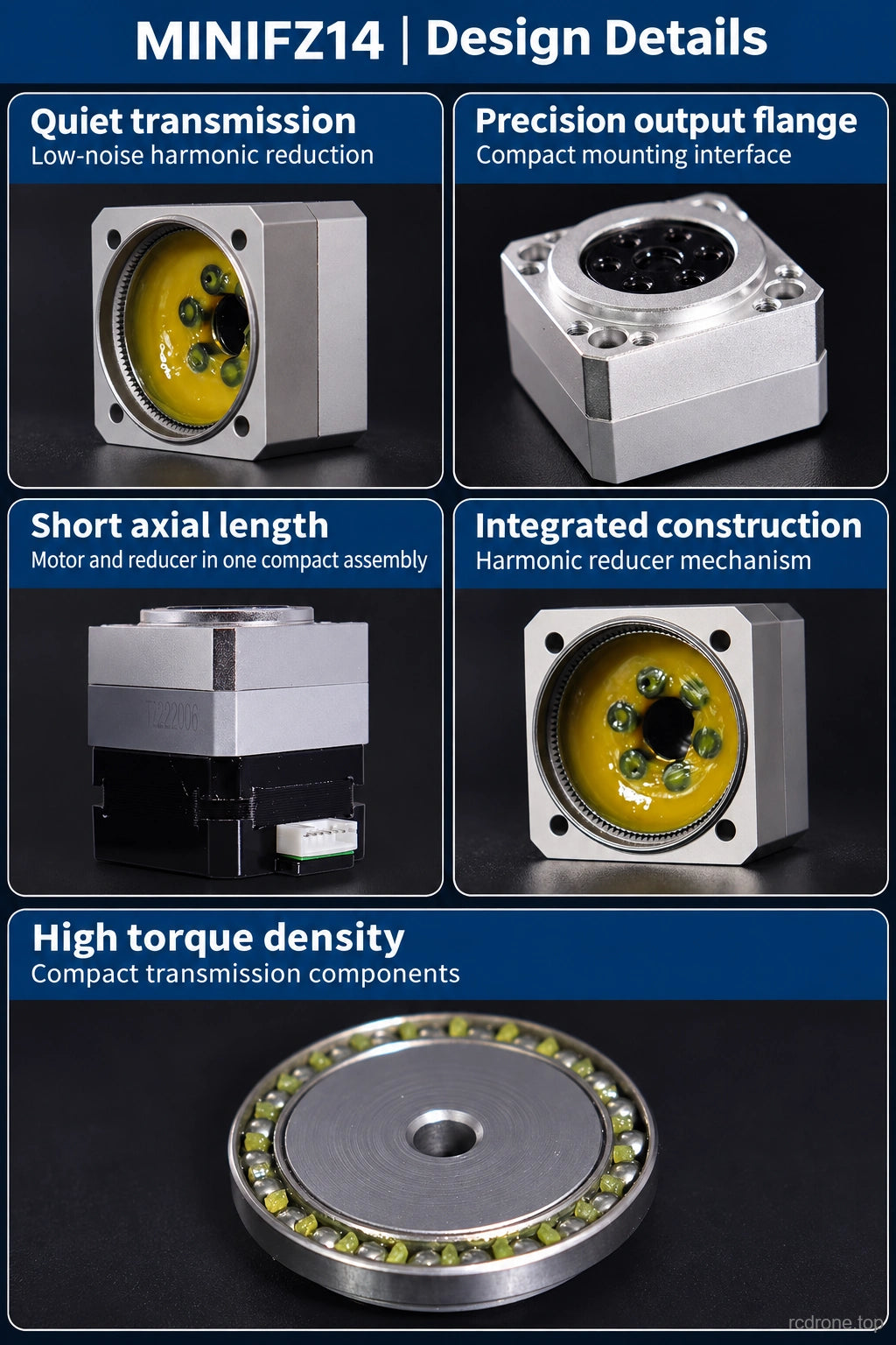
- Low-noise transmission and compact torque delivery for space-limited mechanisms.
- Threaded output-flange mounting with a compact motor connector.
Configuration Guide
| Assembly | Reduction ratio | Recommended use torque | Ideal full-step output increment |
|---|---|---|---|
| MINIFZ14-30 | 30:1 | 2 N·m | 0.06° |
| MINIFZ14-50 | 50:1 | 4 N·m | 0.036° |
| MINIFZ14-80 | 80:1 | 5 N·m | 0.0225° |
| MINIFZ14-100 | 100:1 | 7 N·m | 0.018° |
The torque values are recommended use values for the listed configurations, not stall-torque or guaranteed continuous-duty ratings. Output increments are calculated from the 1.8° motor step angle divided by the reduction ratio; they do not specify positioning accuracy or backlash.
Specifications
| Parameter | Value |
|---|---|
| Series / motor | MINIFZ14 / 42BYGH23 |
| Motor step angle | 1.8° |
| Drive supply range | 12–24 V, through a suitable current-controlled stepper driver |
| Rated motor phase current | 1.0 A |
| Motor phase voltage | 3.6 V |
| Phase resistance / inductance | 3.6 Ω / 5.8 mH |
| Motor holding / detent torque | 130 mN·m / 20 mN·m |
| Motor rotor inertia | 30 g·cm² |
| Reducer rotational inertia | 21 g·cm² |
| Motor input speed guideline | 100–500 rpm; reducer output speed equals motor speed divided by the selected ratio |
| Motor body length | 23 mm |
| Assembly front face / overall length | 42.5 × 42.5 mm / 47 mm |
| Motor-only mass | 0.13 kg; excludes the reducer |
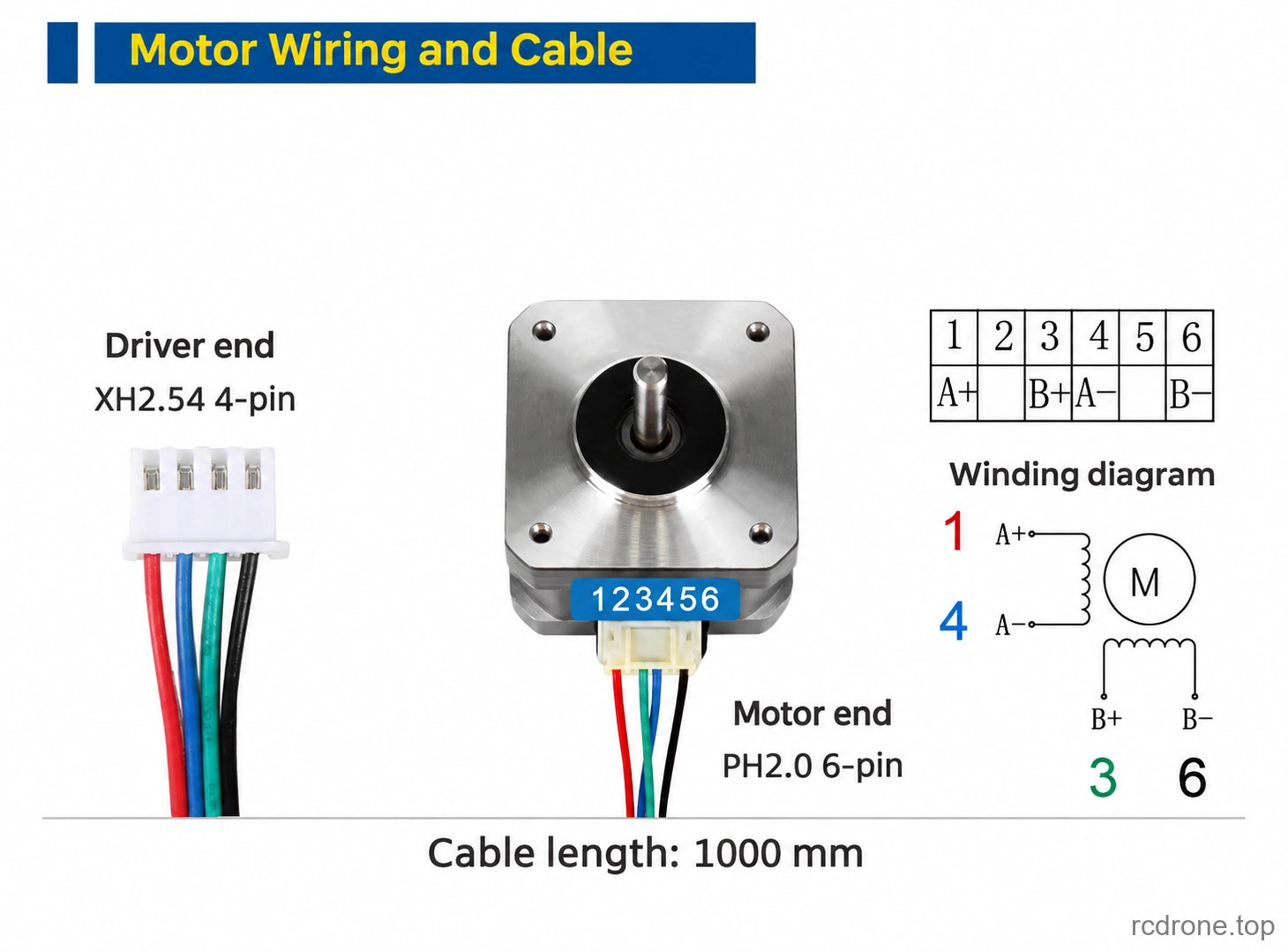
| Motor connector | PH2.0 6-position housing, four active motor connections |
| Cable drawing | XH2.54 4-pin driver end to PH2.0 6-pin motor end; 1000 mm length |
Installation and Wiring
Use a two-phase current-controlled stepper driver set appropriately for the 1.0 A motor. The 12–24 V range is the driver supply guideline; do not connect the motor windings directly to that supply.
| Motor connector pin | Phase | Wire color |
|---|---|---|
| 1 | A+ | Red |
| 4 | A− | Blue |
| 3 | B+ | Green |
| 6 | B− | Black |
| 2, 5 | Unused | — |
Match the connector orientation to the wiring diagram and verify coil pairs before applying power. The shaft motor shown in the cable illustration is a wiring reference, not an additional included motor. Check the mechanical drawing for hole positions, thread depths and locating fits before machining mating parts.
Applications
- Compact robot-joint and rotary-axis development where short axial length matters.
- Small positioning platforms, fixtures and instrument mechanisms needing geared stepper motion.
- Custom automation prototypes that use an external stepper driver and controller.
What's Included
One MINIFZ14 harmonic reducer with integrated 42BYGH23 stepper motor, in the selected reduction ratio. The package does not include a stepper driver, controller, power supply, robot or installation fixture. The cable illustration describes the connector arrangement; it does not establish that a separate cable is included.
FAQ
Does the assembly contain a built-in driver?
No. Use a separate two-phase current-controlled stepper driver matched to the motor's 1.0 A phase rating.
Does a higher ratio mean faster output motion?
No. At the same motor speed, a higher ratio gives lower output speed and a smaller theoretical output step. Select the ratio using the torque and motion requirements of your mechanism.
Is the theoretical step increment the positioning accuracy?
No. It describes the ideal angular movement for one full motor step after reduction. Mechanical backlash, load and the drive setup also affect positioning.
Visual Details