Motore DC Riduttore Encoder Tipo L 520 12V 1:40 300RPM con Encoder Hall AB per Telaio Auto Robot
Motore DC Riduttore Encoder Tipo L 520 12V 1:40 300RPM con Encoder Hall AB per Telaio Auto Robot
Yahboom
Impossibile caricare la disponibilità di ritiro
Panoramica
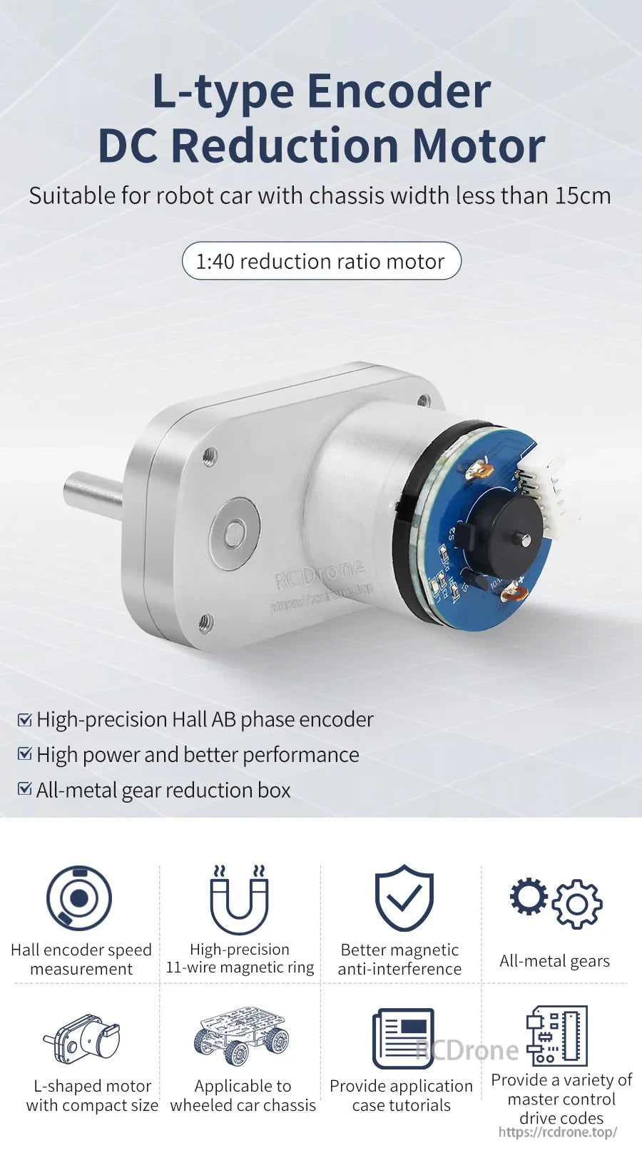
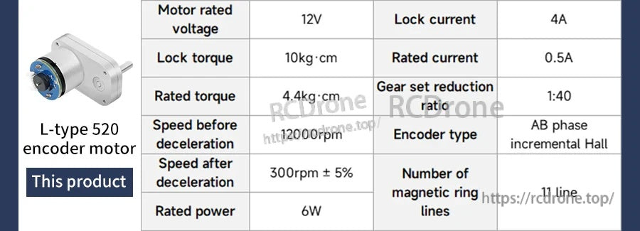
Il motore a corrente continua con riduzione L-type 520 Encoder è un motore a ingranaggi DC compatto e ad alta coppia, progettato per auto robot e altre installazioni con spazio limitato. Utilizza un riduttore con rapporto di riduzione 1:40 e un encoder Hall di alta precisione a fase AB (encoder Hall incrementale AB) per la misurazione della velocità e il rilevamento della direzione. Questo layout del motore a forma di L è adatto per telai di auto robot con larghezza inferiore a 15 cm e può essere disposto per design di robot ultra-narrow con la larghezza minima di circa 110 mm.
Caratteristiche principali
- Motore con rapporto di riduzione 1:40
- Encoder Hall AB ad alta precisione per la misurazione della velocità
- Encoder Hall incrementale AB; MCU può leggere direttamente i segnali di impulso
- Riduttore di ingranaggi completamente in metallo (ingranaggi in metallo)
- Design migliore contro le interferenze magnetiche; anello magnetico a 11 fili
- Struttura del motore compatta a forma di L per layout di chassis ristretti
- Basso rumore e bassa vibrazione (come descritto)
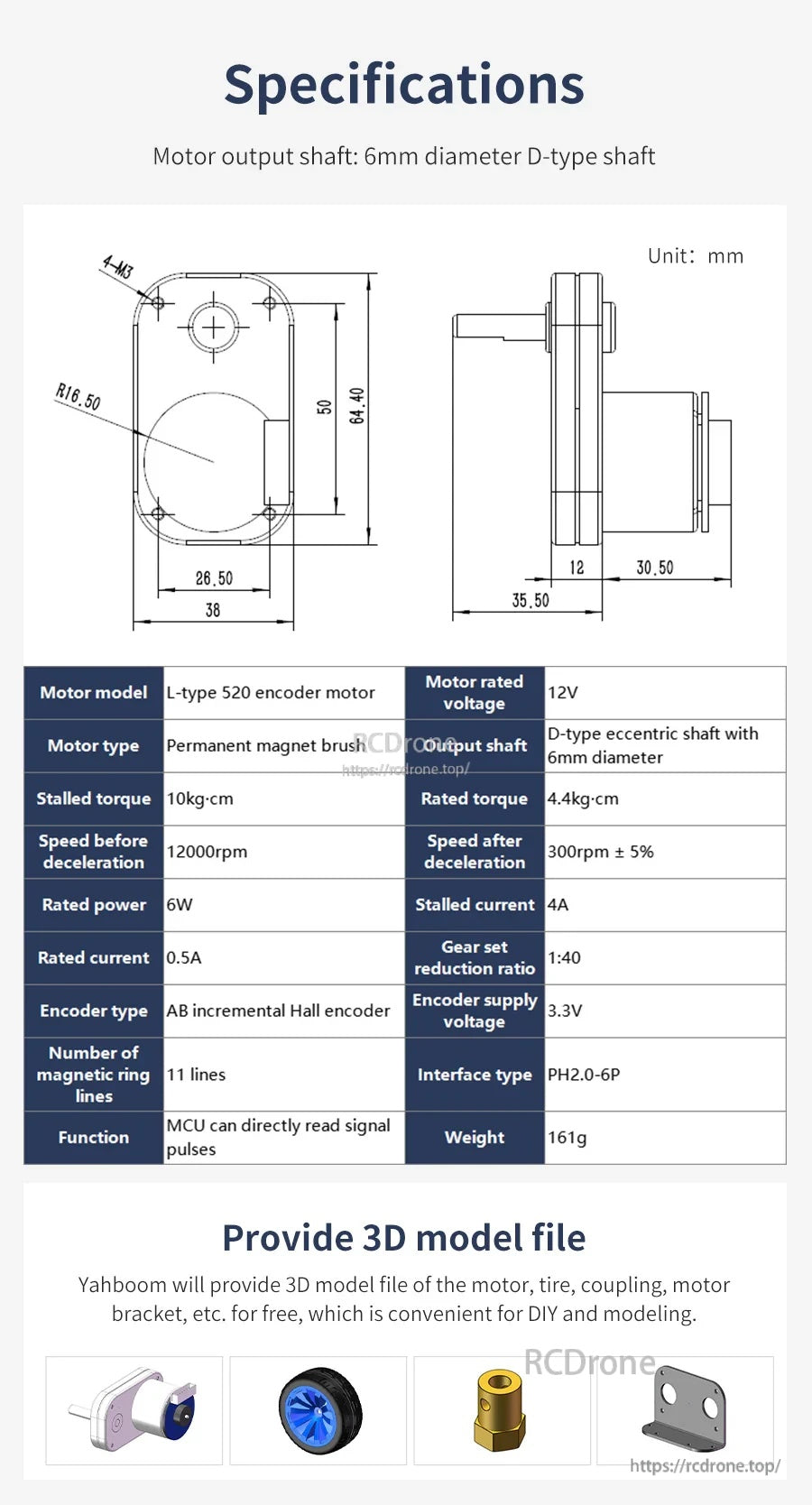
Specifiche
| Modello del motore | Motore encoder L-type 520 |
| Tipo di motore | Motore a spazzole con magnete permanente |
| Tensione nominale del motore | 12V |
| Rapporto di riduzione del set di ingranaggi | 1:40 |
| Velocità prima della decelerazione | 12000 rpm |
| Velocità dopo la decelerazione | 300 rpm ± 5% |
| Momento torcentale nominale | 4.4 kg·cm |
| Momento di stallo | 10 kg·cm |
| Potenza nominale | 6 W |
| Corrente nominale | 0.5 A |
| Corrente di stallo | 4 A |
| Albero di uscita | Albero eccentrico di tipo D con diametro di 6 mm |
| Albero di uscita del motore | Albero di tipo D con diametro di 6 mm |
| Tipo di encoder | Encoder Hall incrementale AB |
| Voltaggio di alimentazione dell'encoder | 3.3 V |
| Numero di linee dell'encoder | 11 ppr |
| Numero di linee del anello magnetico | 11 linee |
| Tipo di interfaccia dell'encoder | PH2.0-6P |
| Tipo di encoder (tabella dei parametri) | Induzione magnetica |
| Protezione dell'encoder | Esposto (l'encoder magnetico è più stabile e non richiede una copertura posteriore) |
| MCU applicabile | Quasi tutte le MCU |
| Peso | 161 g |
Dimensioni (unità: mm)
- Dimensioni complessive (elencate): 66 × 38 × 64.4 mm
- Larghezza vista frontale: 38
- Larghezza interna vista frontale: 26.50
- Altezza vista frontale: 64.40
- Marcatura dell'altezza interna vista frontale: 50
- Raggio d'angolo: R16.50
- Marcatura di montaggio: 4-M3
- Marcature di lunghezza vista laterale: 35.50, 12, 30.50
Descrizione dell'uscita dell'encoder
La differenza di fase tra i due segnali è di 100°, e la direzione di rotazione del motore può essere determinata in base all'ordine dei due segnali. La distanza attuale percorsa dal pneumatico può essere calcolata in base al numero di impulsi di segnale per unità di tempo e alla circonferenza del pneumatico. Se viene rilevato solo il numero di impulsi di fase AB per unità di tempo, anche la velocità attuale del motore può essere misurata.
Esempio mostrato: prendere un motore con un rapporto di riduzione 1:30 come esempio. Il motore emette 11 impulsi per singola fase quando il motore ruota di un cerchio. Con un rapporto di riduzione 1:30, l'uscita massima dell'albero di uscita del motore è di (30 × 11 × 4) = 1320 conteggi per rotazione.
Applicazioni
- Chassis per auto robot a ruote (inclusi layout di chassis stretti)
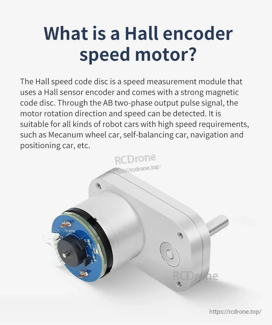
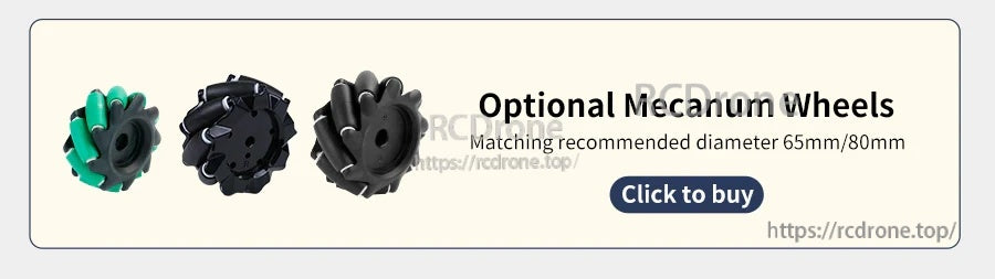
- Auto con ruote Mecanum, auto auto-bilancianti, auto per navigazione e posizionamento (come descritto)
- Progetti di robotica fai-da-te e controllo del movimento che richiedono feedback di velocità
Per assistenza nella selezione e integrazione dei prodotti (cablaggio, interfaccia encoder PH2.0-6P e lettura dei impulsi MCU), contattare [email protected] or visitare https://rcdrone.top/.
Dettagli
Un motore a ingranaggi DC compatto a forma di L con un rapporto di riduzione di 1:40 e encoder Hall di fase AB per feedback di velocità e direzione.
Le dimensioni chiave e le specifiche elettriche sono riassunte per un'integrazione rapida, inclusi i dettagli dell'albero di uscita D-type da 6 mm e del connettore dell'encoder.
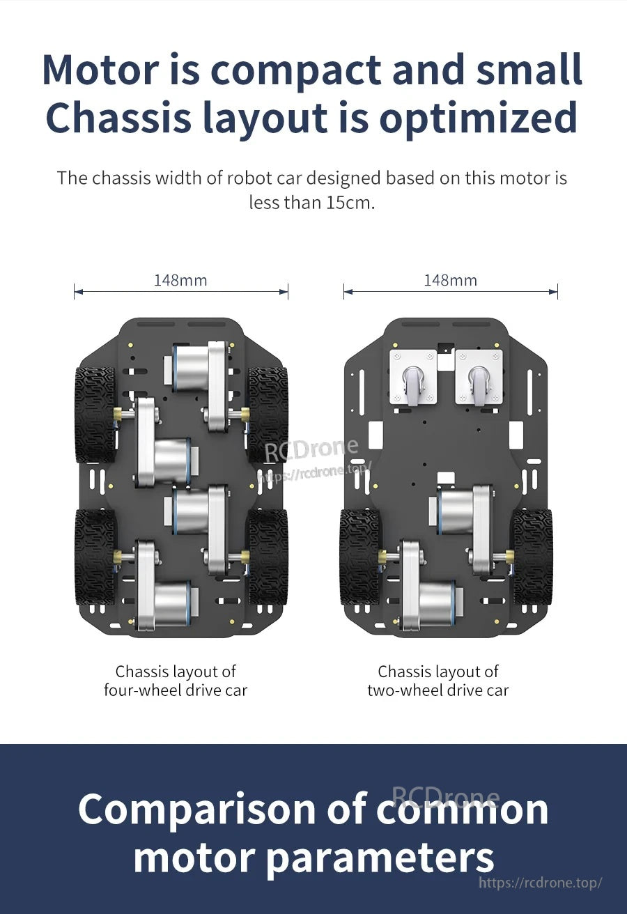
Il fattore di forma a L aiuta a mantenere i layout degli chassis delle auto robot stretti, lasciando spazio per ruote, supporti e cablaggio.
I punti salienti dei parametri affiancati rendono più facile confrontare il rapporto di riduzione, la velocità e la coppia rispetto alle alternative comuni.
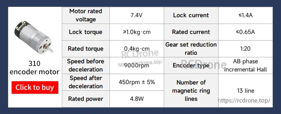
Un confronto di riferimento contro un motore encoder 310 quando si seleziona una dimensione del motore e un rapporto di riduzione per il proprio progetto.
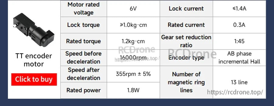
Un'opzione di confronto rapido per i motori encoder TT quando si valuta la velocità, la coppia e la corrente per piccole piattaforme robotiche.
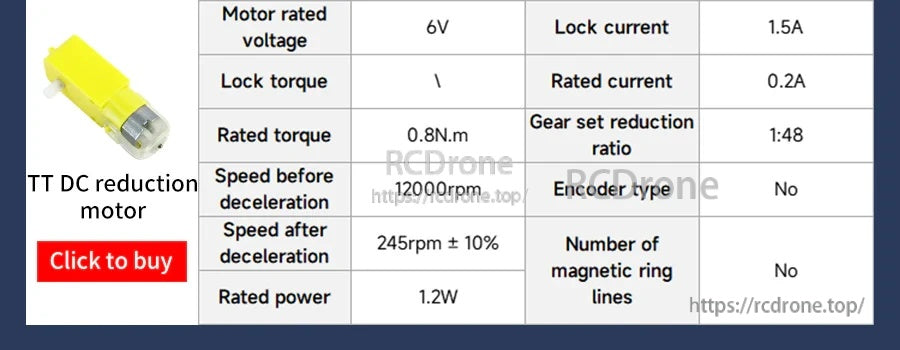
Per progetti che non richiedono feedback in anello chiuso, i motori a ingranaggi TT non encoder possono essere confrontati qui per potenza e velocità.
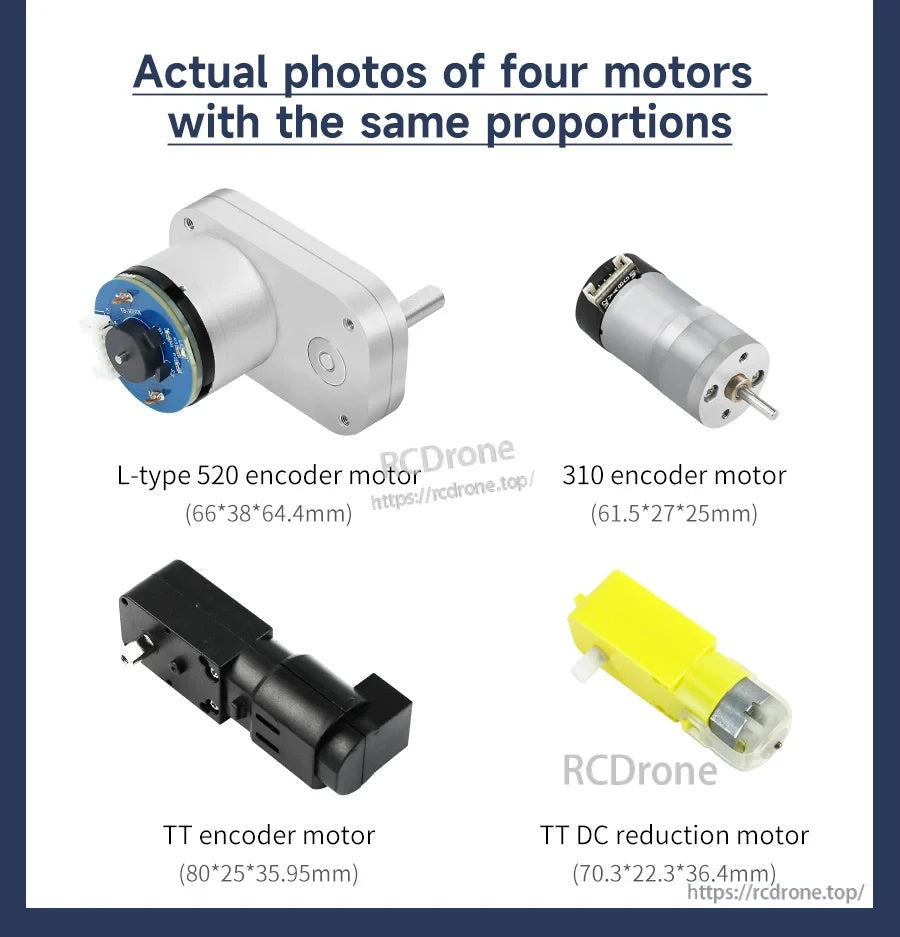
Una panoramica delle dimensioni in scala aiuta a confermare l'adattamento tra gli stili di motore più popolari prima di finalizzare un layout del telaio.
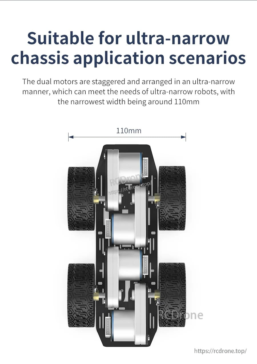
Il montaggio sfalsato supporta design robotici ultra-narrow, con una larghezza del telaio che può essere disposta fino a circa 110 mm.
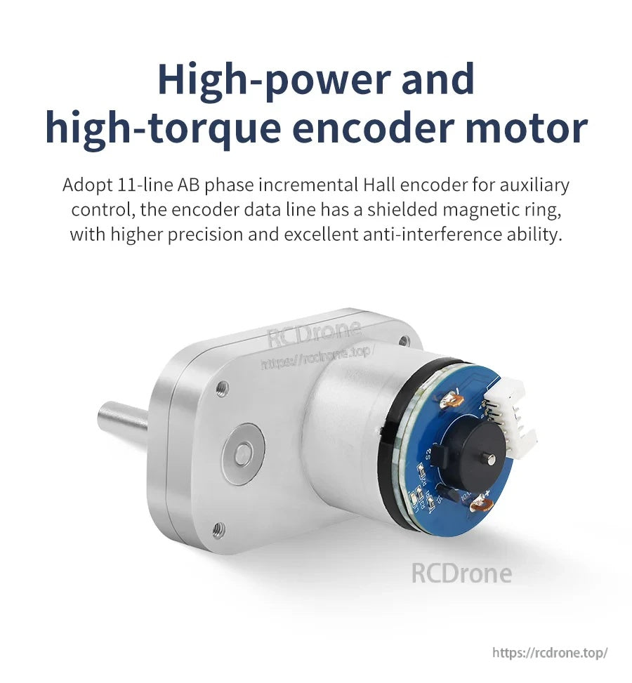
L'encoder Hall integrato fornisce segnali AB puliti per la misurazione della velocità e la rilevazione della direzione nei loop di controllo.
L'uscita incrementale in fase AB consente ai comuni MCU di leggere i conteggi dei impulsi per la stima della velocità e determinare la direzione di rotazione.
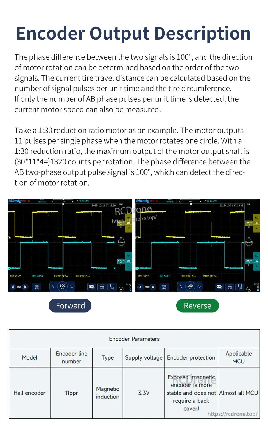
Esempi di forme d'onda avanti/indietro illustrano come l'ordine di fase cambi con la direzione, supportando un'odometria e un controllo della velocità affidabili.
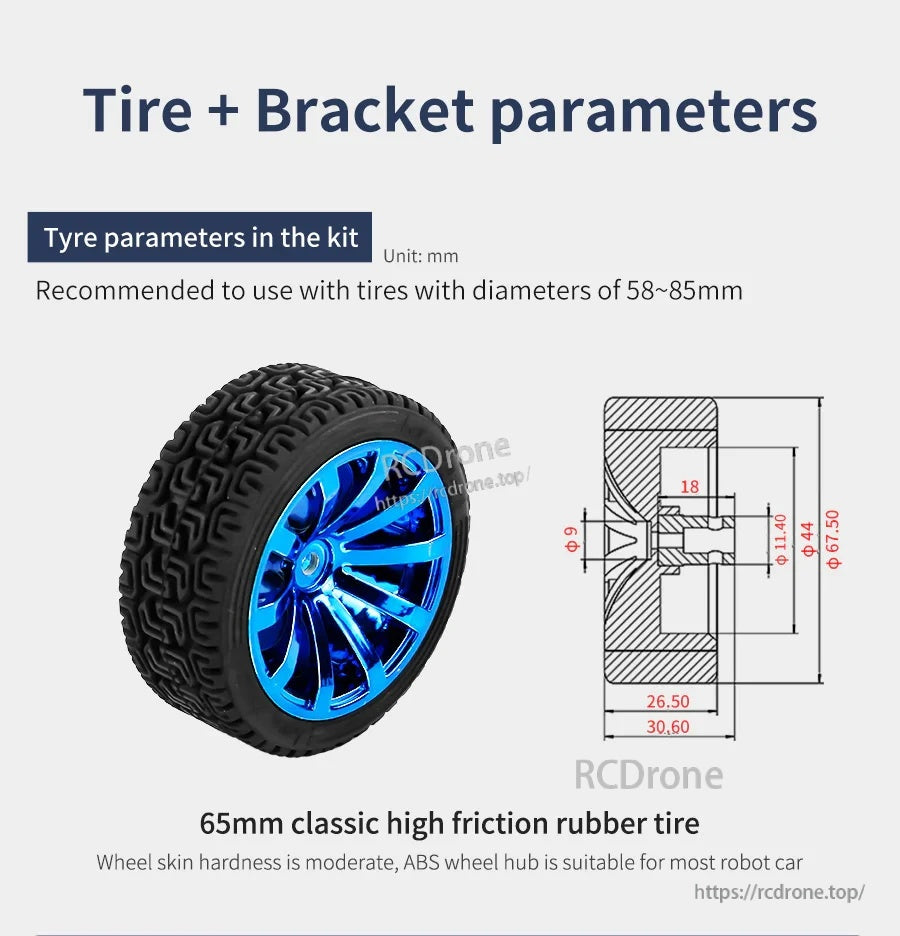
Le indicazioni per la dimensione delle ruote aiutano a abbinare il diametro degli pneumatici alla geometria del telaio e all'altezza da terra prevista.
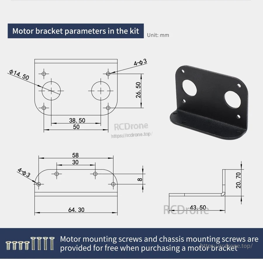
Le dimensioni del supporto di montaggio e la spaziatura dei fori sono fornite per semplificare la progettazione e l'allineamento del telaio.
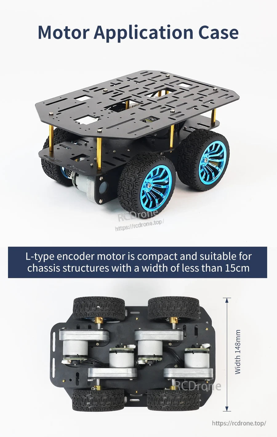
Un esempio di costruzione dimostra come il motore si adatti a piattaforme di auto robotiche compatte progettate con una larghezza inferiore a 15 cm.

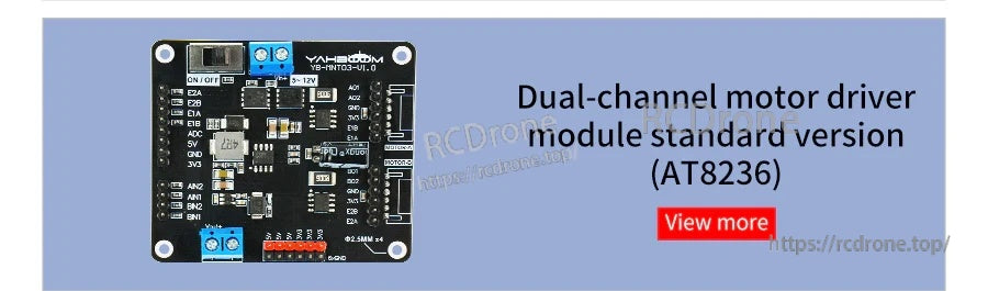
Il modulo driver per motori a doppio canale AT8236 fornisce terminali e connettori etichettati per un cablaggio e un controllo semplici di due motori DC.
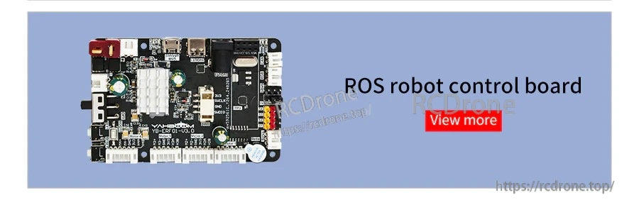
La scheda di controllo del robot ROS fornisce un PCB compatto con porte USB accessibili e connettori per collegare periferiche.
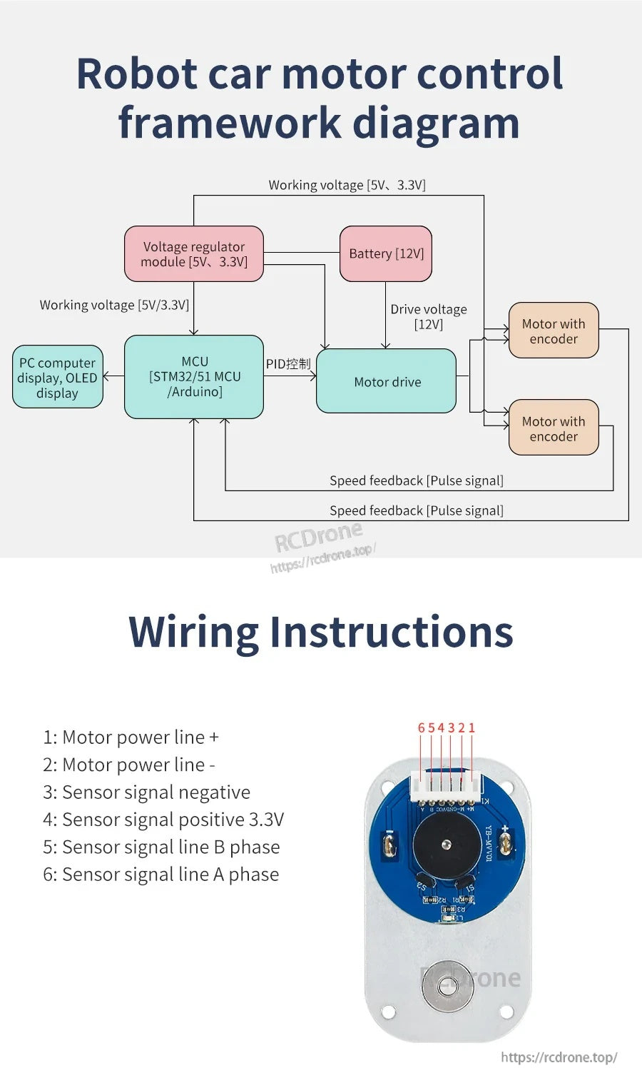
La guida al cablaggio etichetta l'alimentazione del motore, 3.3V, terra e segnali di feedback di fase A/B per collegare un motore a corrente continua con riduzione a un controller.
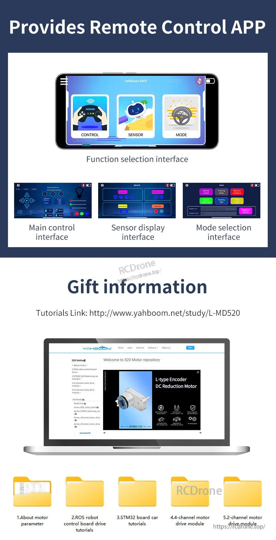
L'app di controllo remoto fornisce un pannello di controllo principale più schermi di visualizzazione dei sensori e selezione della modalità per configurazione e funzionamento.
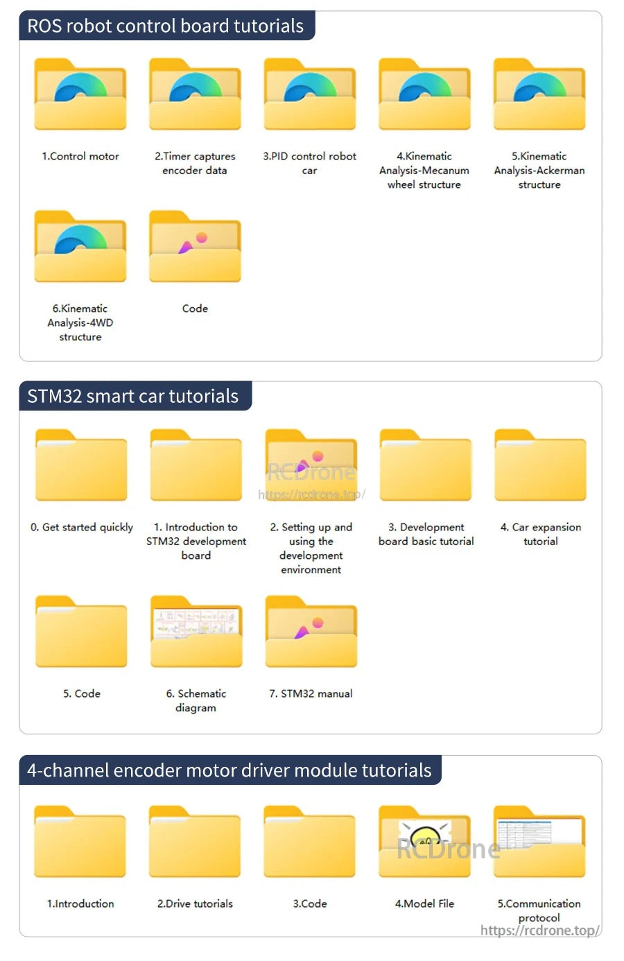
Le cartelle dei tutorial includono guide alla scheda di controllo del robot ROS, nozioni di base sulla smart car STM32 e documentazione del modulo driver motore con encoder a 4 canali.
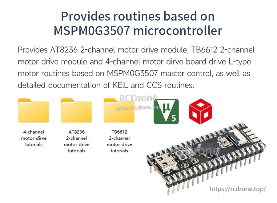
Le routine di controllo basate su MSPM0G3507 sono fornite per i moduli di guida motore AT8236 e TB6612, inclusi opzioni a 2 canali e 4 canali.
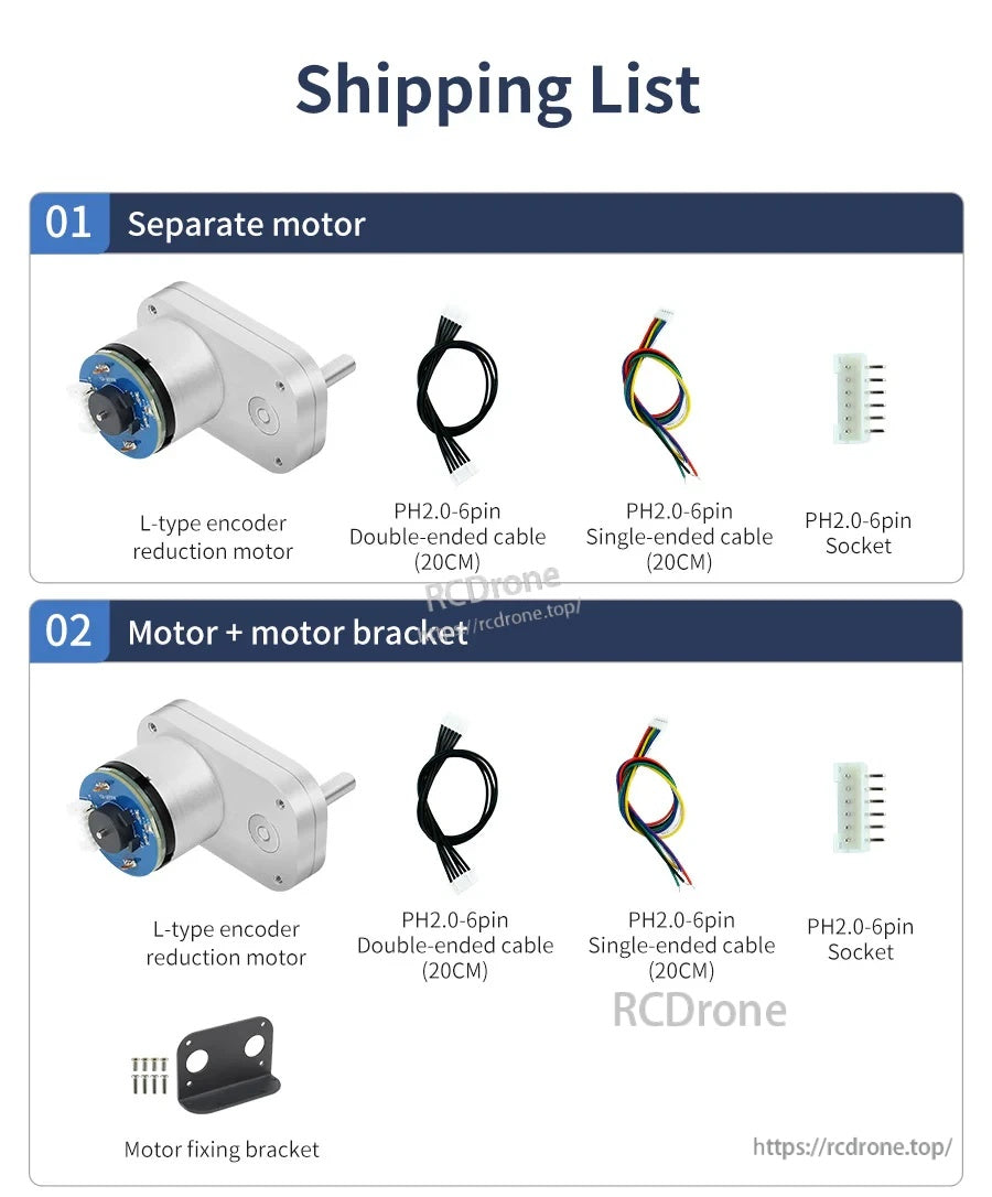
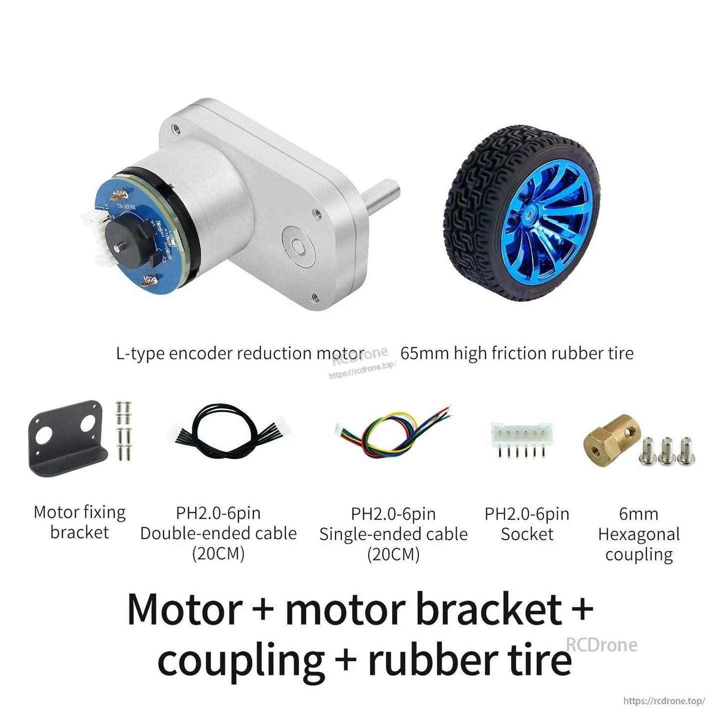
Il motore a riduzione con encoder di tipo L è fornito con una presa PH2.0 a 6 pin e cavi da 20 cm, con un supporto per il fissaggio del motore opzionale.
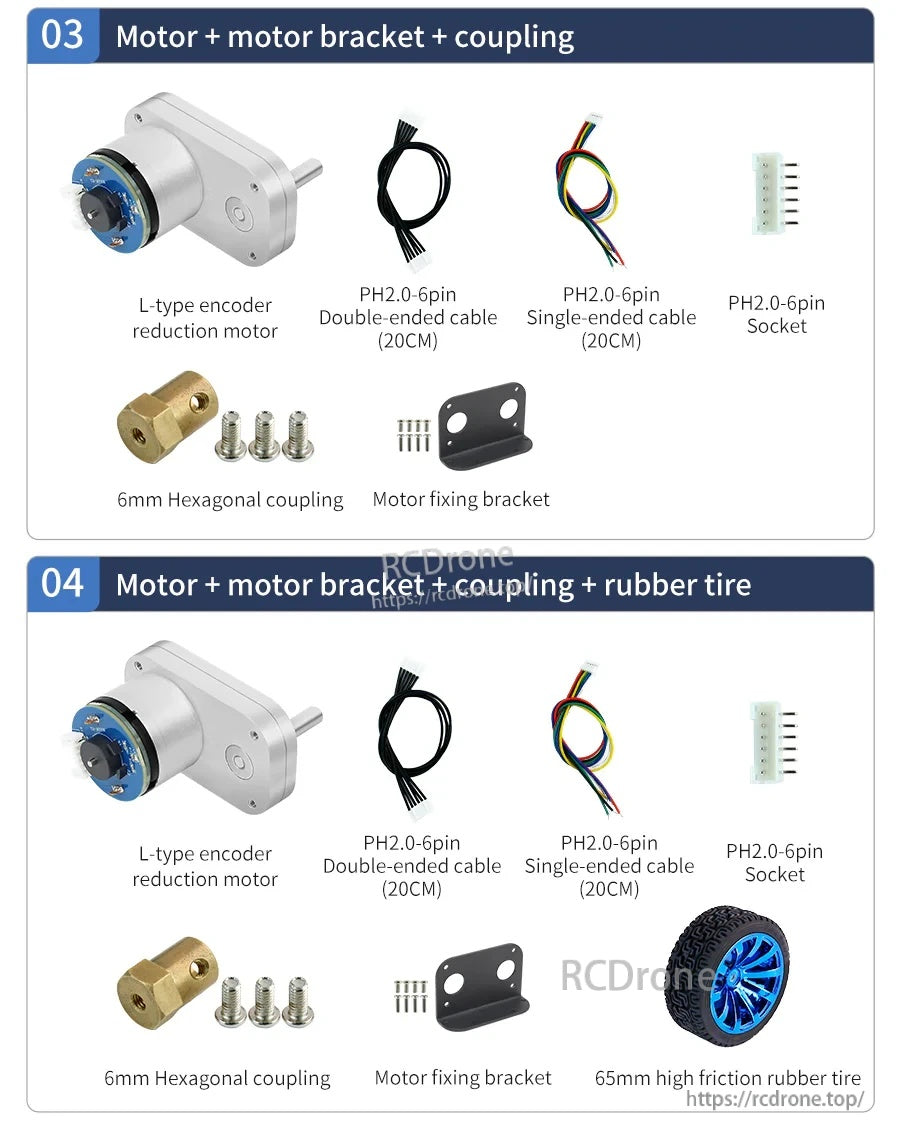
Il set del motore a riduzione DC con encoder di tipo L 520 include un supporto per il motore, un accoppiamento esagonale da 6 mm, cavi PH2.0-6pin e una presa, con un pneumatico in gomma ad alta frizione opzionale da 65 mm.
Related Collections