L형 520 엔코더 DC 감속 모터 12V 1:40 기어박스 300RPM 홀 AB 엔코더 로봇 자동차 섀시용
L형 520 엔코더 DC 감속 모터 12V 1:40 기어박스 300RPM 홀 AB 엔코더 로봇 자동차 섀시용
Yahboom
픽업 사용 가능 여부를 로드할 수 없습니다.
개요
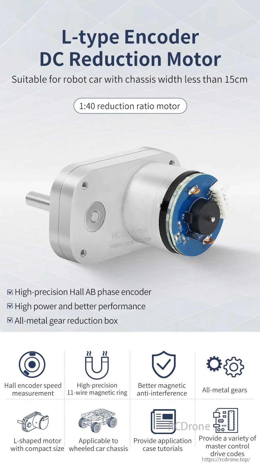
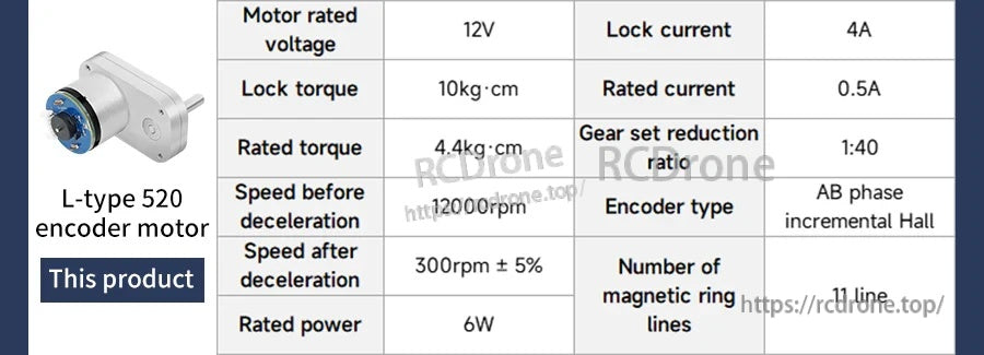
L형 520 인코더 DC 감속 모터는 로봇 자동차 및 기타 공간 제약이 있는 설치를 위해 설계된 컴팩트하고 고토크의 DC 기어 모터입니다. 1:40 감속비 기어박스와 고정밀 홀 AB-위상 인코더(AB 증분 홀 인코더)를 사용하여 속도 측정 및 방향 감지를 수행합니다. 이 L자형 모터 배치는 로봇 자동차 섀시 폭이 15cm 미만인 경우에 적합하며, 가장 좁은 폭이 약 110mm인 초협소 로봇 설계를 위해 배열할 수 있습니다.
주요 특징
- 1:40 감속비 모터
- 속도 측정을 위한 고정밀 홀 AB-상 인코더
- AB 증분 홀 인코더; MCU가 신호 펄스를 직접 읽을 수 있음
- 전금속 기어 감속 박스 (전금속 기어)
- 더 나은 자기 간섭 방지 설계; 11선 자기 링
- 조밀한 섀시 레이아웃을 위한 컴팩트 L형 모터 구조
- 낮은 소음과 낮은 진동 (설명된 대로)
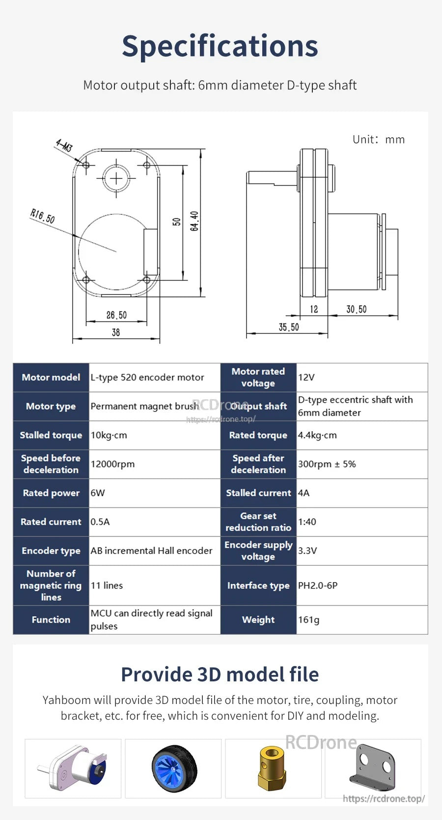
사양
| 모터 모델 | L형 520 인코더 모터 |
| 모터 유형 | 영구 자석 브러시 모터 |
| 모터 정격 전압 | 12V |
| 기어 세트 감속비 | 1:40 |
| 감속 전 속도 | 12000 rpm |
| 감속 후 속도 | 300 rpm ± 5% |
| 정격 토크 | 4.4 kg·cm |
| 정지 토크 | 10 kg·cm |
| 정격 전력 | 6 W |
| 정격 전류 | 0.5 A |
| 정지 전류 | 4 A |
| 출력 샤프트 | 6 mm 직경의 D형 편심 샤프트 |
| 모터 출력 샤프트 | 6 mm 직경의 D형 샤프트 |
| 인코더 유형 | AB 증분 홀 인코더 |
| 인코더 공급 전압 | 3.3 V |
| 인코더 라인 수 | 11 ppr |
| 자기 링 라인 수 | 11 라인 |
| 인코더 인터페이스 유형 | PH2.0-6P |
| 인코더 유형 (매개변수 표) | 자기 유도 |
| 인코더 보호 | 노출형 (자기 인코더는 더 안정적이며 백커버가 필요하지 않음) |
| 적용 가능한 MCU | 거의 모든 MCU |
| 무게 | 161 g |
치수 (단위: mm)
- 전체 크기 (기재된): 66 × 38 × 64.4 mm
- 정면 너비: 38
- 정면 내부 너비: 26.50
- 정면 높이: 64.40
- 정면 내부 높이 표기: 50
- 모서리 반경: R16.50
- 장착 표기: 4-M3
- 측면 길이 표기: 35.50, 12, 30.50
인코더 출력 설명
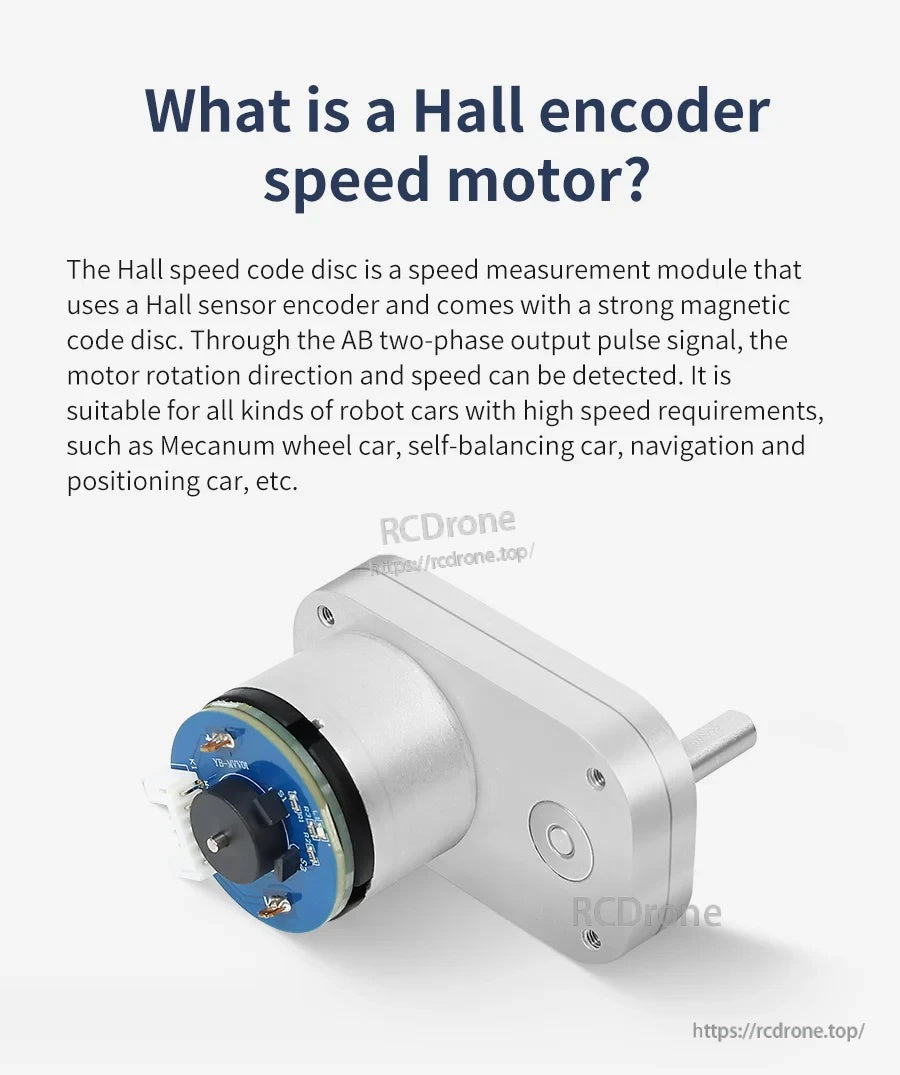
두 신호 간의 위상 차이는 100°이며, 두 신호의 순서에 따라 모터 회전 방향을 결정할 수 있습니다. 현재 타이어 주행 거리는 단위 시간당 신호 펄스 수와 타이어 둘레를 기반으로 계산할 수 있습니다. 단위 시간당 AB 위상 펄스 수만 감지되면 현재 모터 속도도 측정할 수 있습니다.
예시: 1:30 감속비 모터를 예로 들면, 모터가 한 바퀴 회전할 때 단일 위상당 11개의 펄스를 출력합니다. 1:30 감속비를 적용하면, 모터 출력 샤프트의 최대 출력은 (30 × 11 × 4) = 1320 카운트/회전입니다.
응용 프로그램
- 바퀴가 달린 로봇 자동차 섀시(좁은 섀시 레이아웃 포함)
- 메카넘 휠 자동차, 자가 균형 자동차, 내비게이션 및 위치 지정 자동차(설명된 대로)
- 속도 피드백이 필요한 DIY 로봇 공학 및 모션 제어 프로젝트
제품 선택 및 통합 도움(배선, 인코더 인터페이스 PH2.0-6P, MCU 펄스 읽기)에 대한 문의는 [email protected] or 방문해 주십시오 https://rcdrone.top/.
세부정보
속도 및 방향 피드백을 위한 1:40 감속비와 AB-상 홀 인코더가 있는 컴팩트 L자형 DC 기어 모터.
주요 치수 및 전기 사양이 빠른 통합을 위해 요약되어 있으며, 6 mm D형 출력 샤프트 및 인코더 커넥터 세부정보가 포함되어 있습니다.
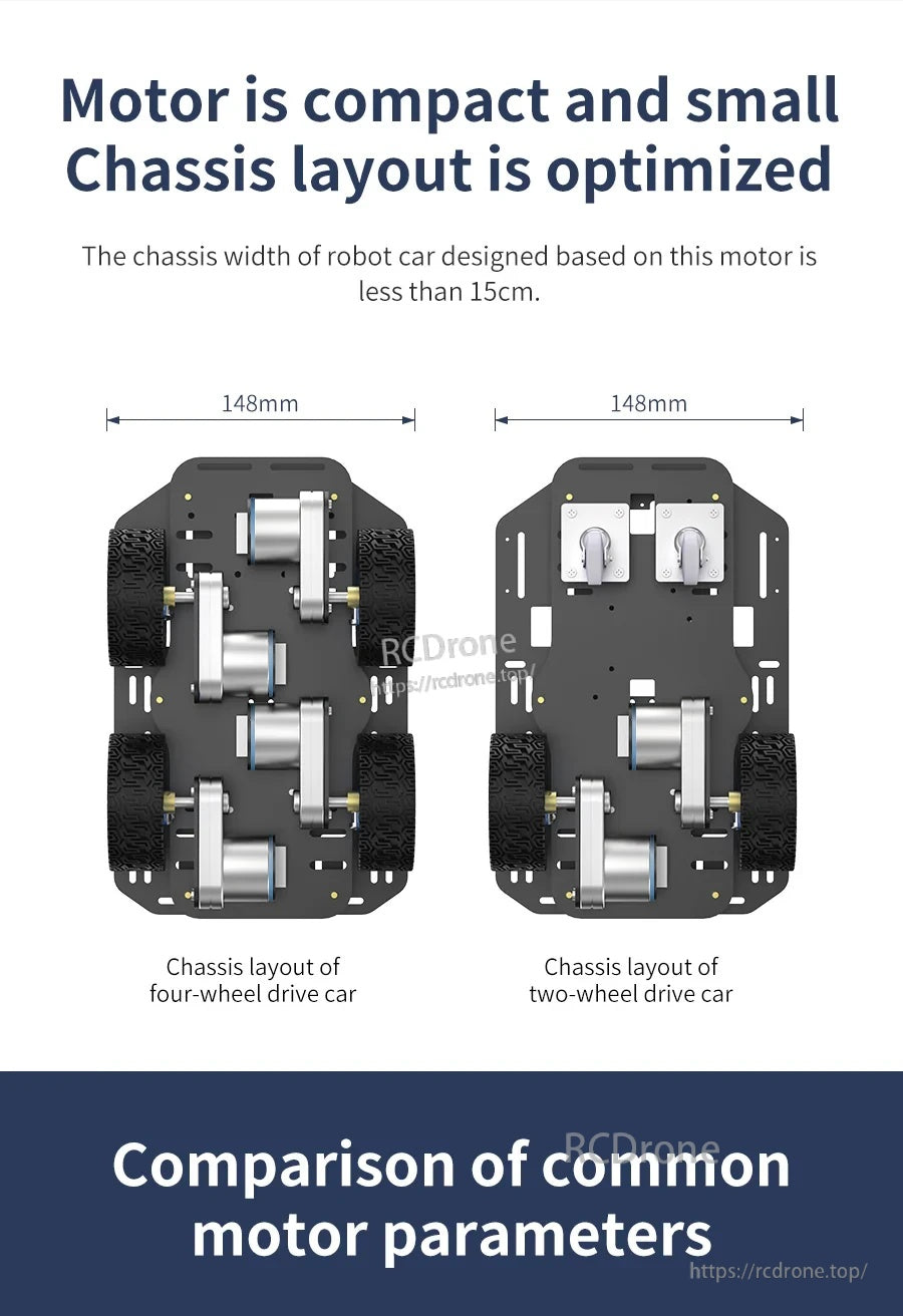
L자형 형태는 로봇 자동차 섀시 레이아웃을 좁게 유지하면서 바퀴, 브래킷 및 배선에 대한 공간을 남기는 데 도움이 됩니다.
나란히 배치된 매개변수 하이라이트는 일반적인 대안과 비교하여 감속비, 속도 및 토크를 비교하는 데 더 쉽게 만들어 줍니다.
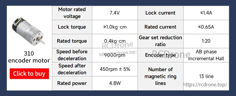
모터 크기 및 감속비를 선택할 때 310 인코더 모터에 대한 참조 비교입니다.
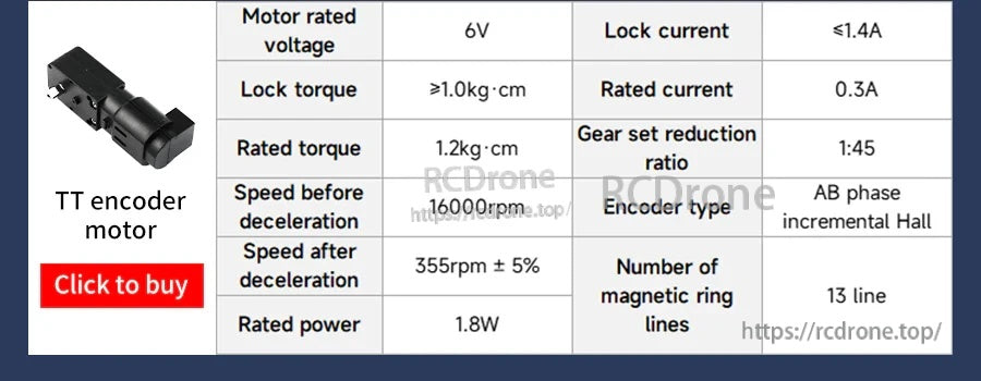
소형 로봇 플랫폼의 속도, 토크 및 전류를 평가할 때 TT 인코더 모터에 대한 빠른 비교 옵션입니다.
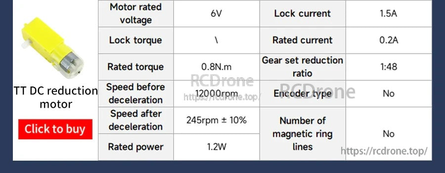
폐쇄 루프 피드백이 필요하지 않은 프로젝트의 경우, 비인코더 TT 기어 모터를 여기에서 전력 및 속도에 대해 비교할 수 있습니다.
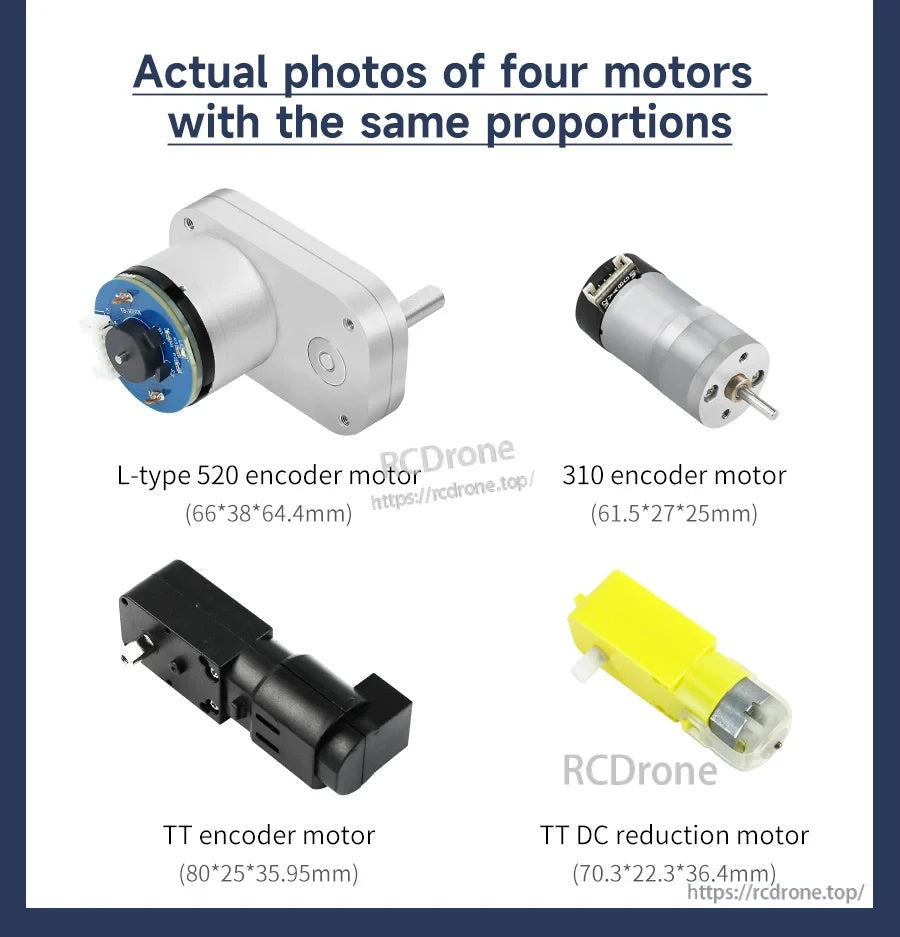
동일한 비율의 크기 개요는 최종 섀시 레이아웃을 확정하기 전에 인기 있는 모터 스타일 간의 적합성을 확인하는 데 도움이 됩니다.
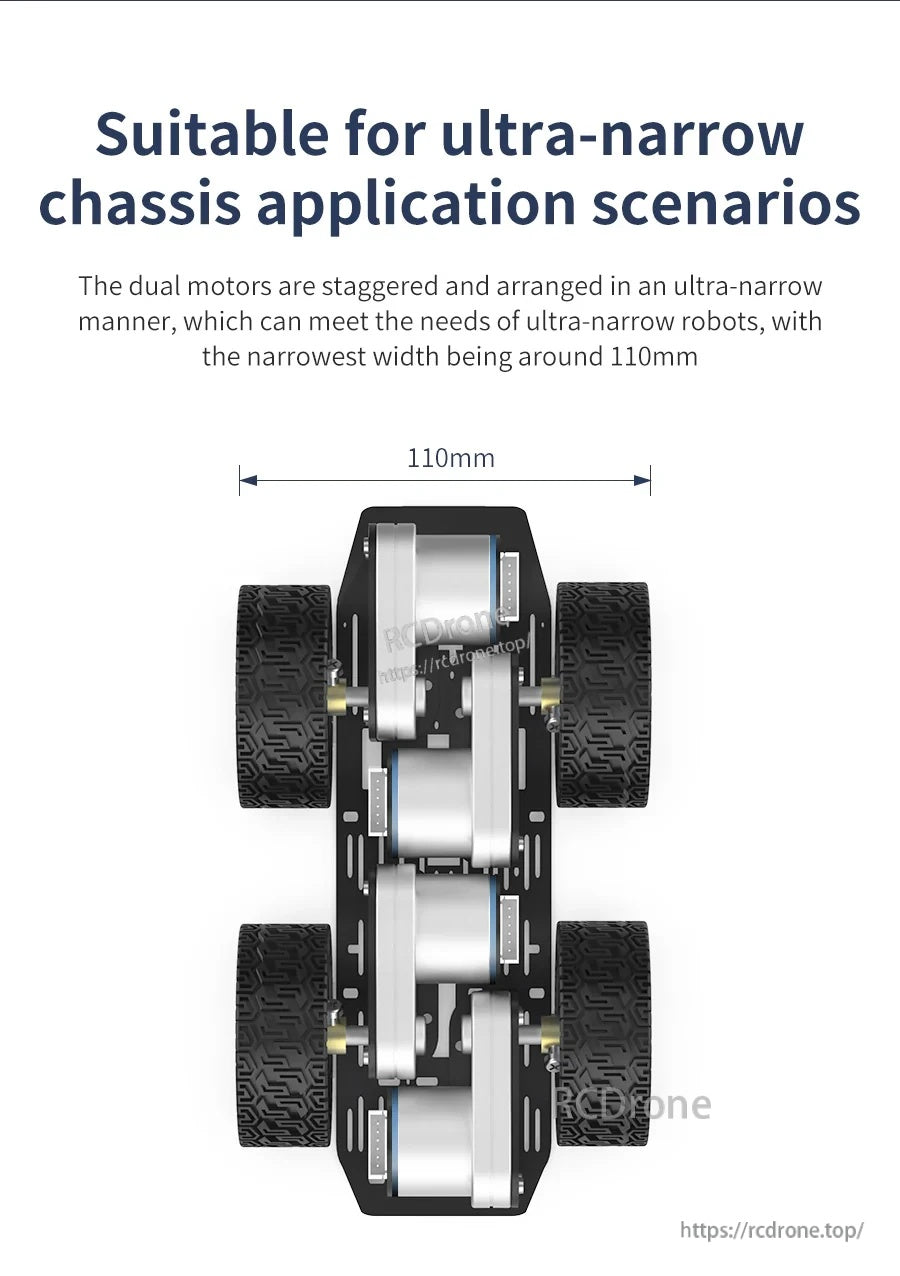
계단식 장착은 초협소 로봇 디자인을 지원하며, 섀시 너비는 약 110mm까지 조정할 수 있습니다.
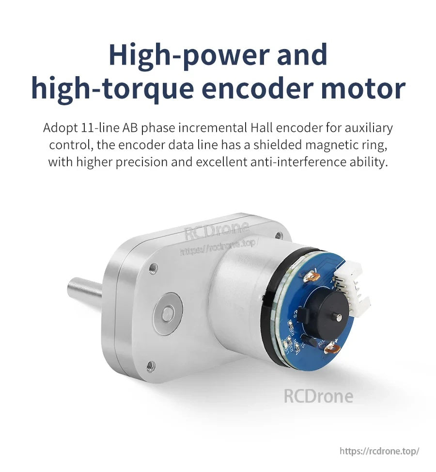
통합된 홀 인코더는 제어 루프에서 속도 측정 및 방향 감지를 위한 깨끗한 AB 신호를 제공합니다.
AB-위상 증분 출력은 일반 MCU가 속도 추정을 위한 펄스 수를 읽고 회전 방향을 결정할 수 있게 합니다.
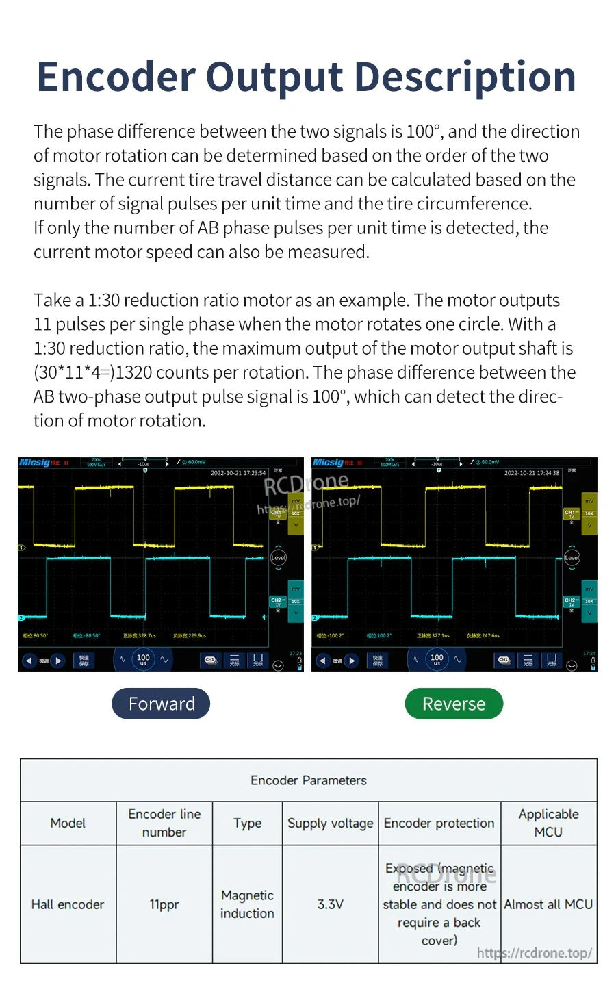
전진/후진 파형 예시는 방향에 따라 위상 순서가 어떻게 변화하는지를 보여주며, 신뢰할 수 있는 오도메트리 및 속도 제어를 지원합니다.
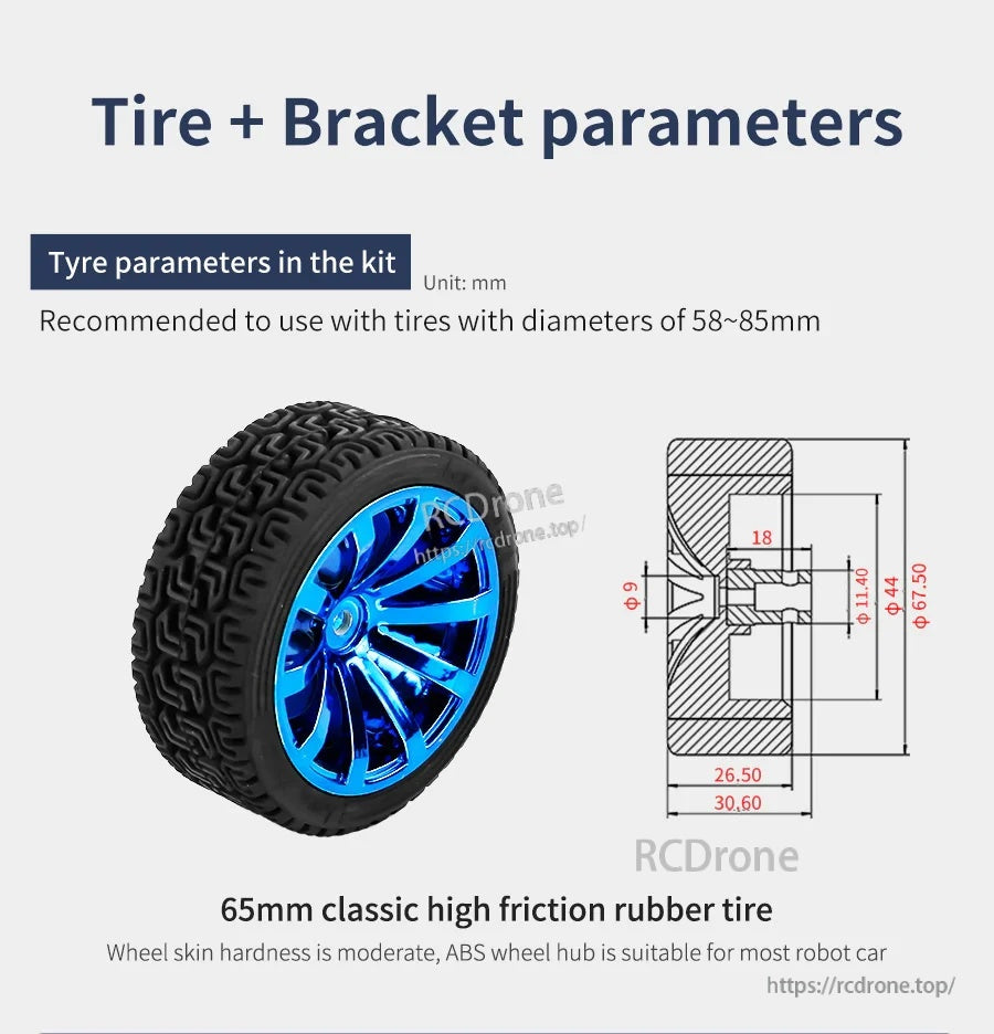
바퀴 크기 안내는 타이어 직경을 섀시 기하학 및 예상 지상 고도에 맞추는 데 도움을 줍니다.
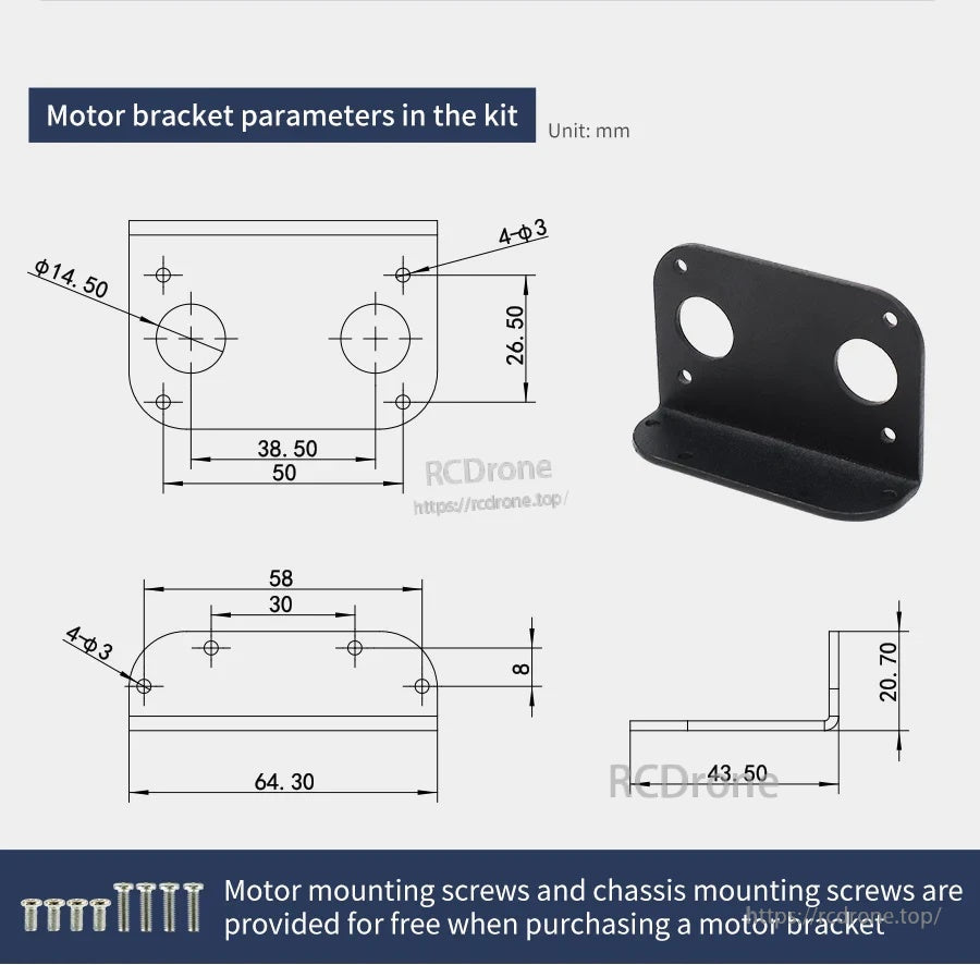
장착 브래킷 치수와 구멍 간격이 제공되어 섀시 설계 및 정렬을 간소화합니다.
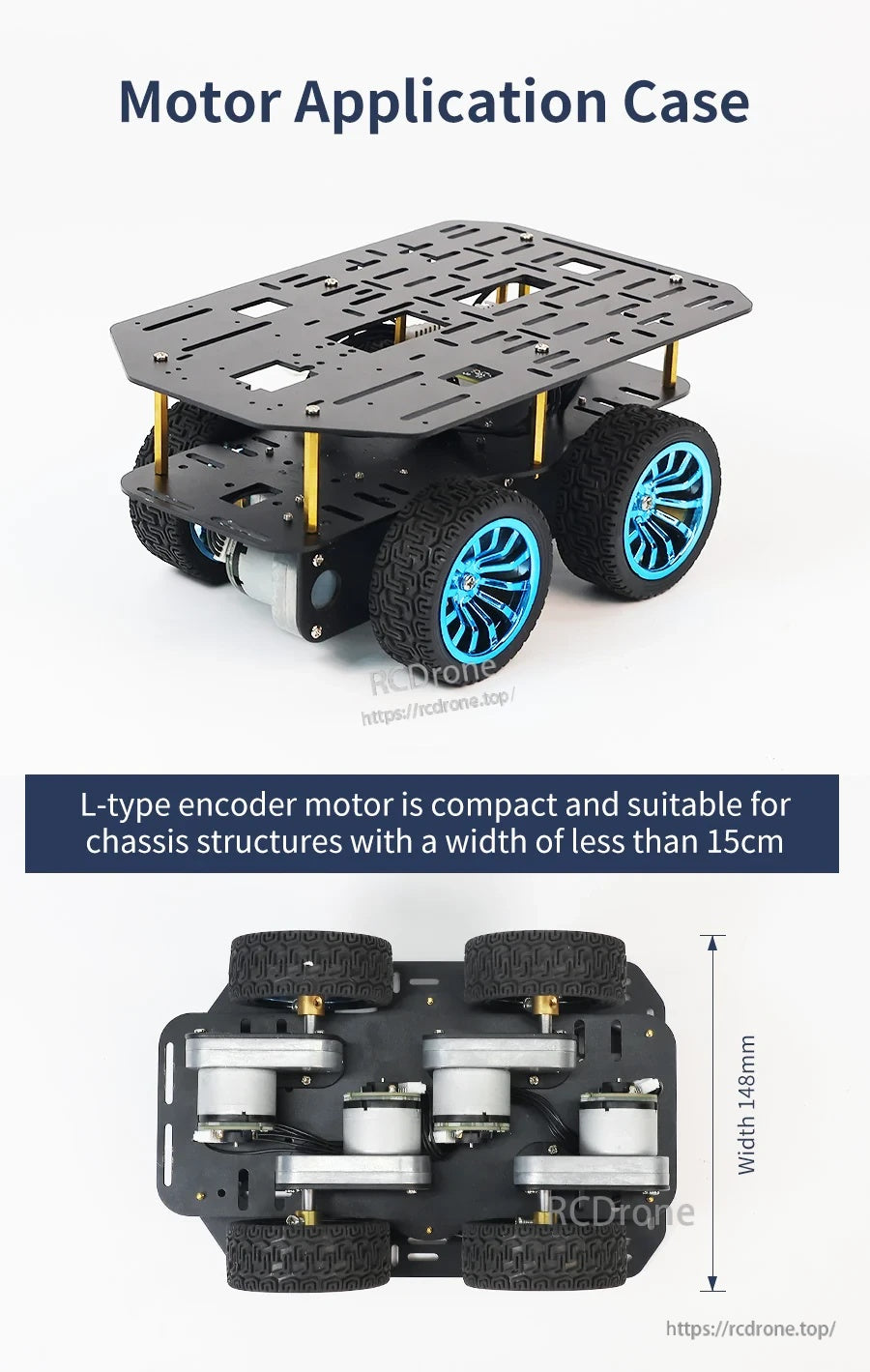
예제 빌드는 모터가 15cm 너비 이하로 설계된 컴팩트 로봇 자동차 플랫폼에 어떻게 적합한지를 보여줍니다.
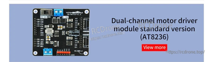
AT8236 듀얼 채널 모터 드라이버 모듈은 두 개의 DC 모터의 간단한 배선 및 제어를 위한 레이블이 붙은 단자와 헤더를 제공합니다.
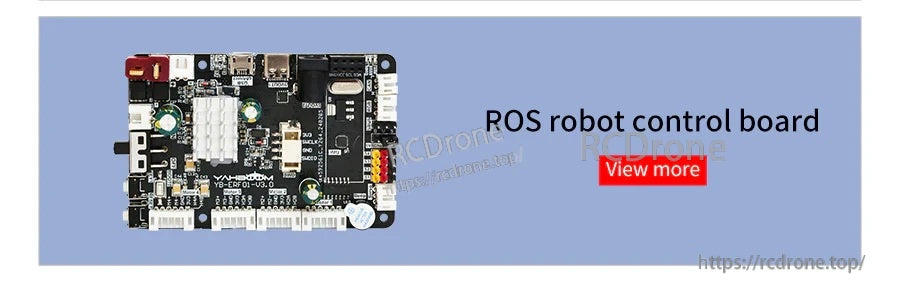
ROS 로봇 제어 보드는 주변 장치를 연결하기 위한 접근 가능한 USB 포트와 헤더가 있는 컴팩트한 PCB를 제공합니다.
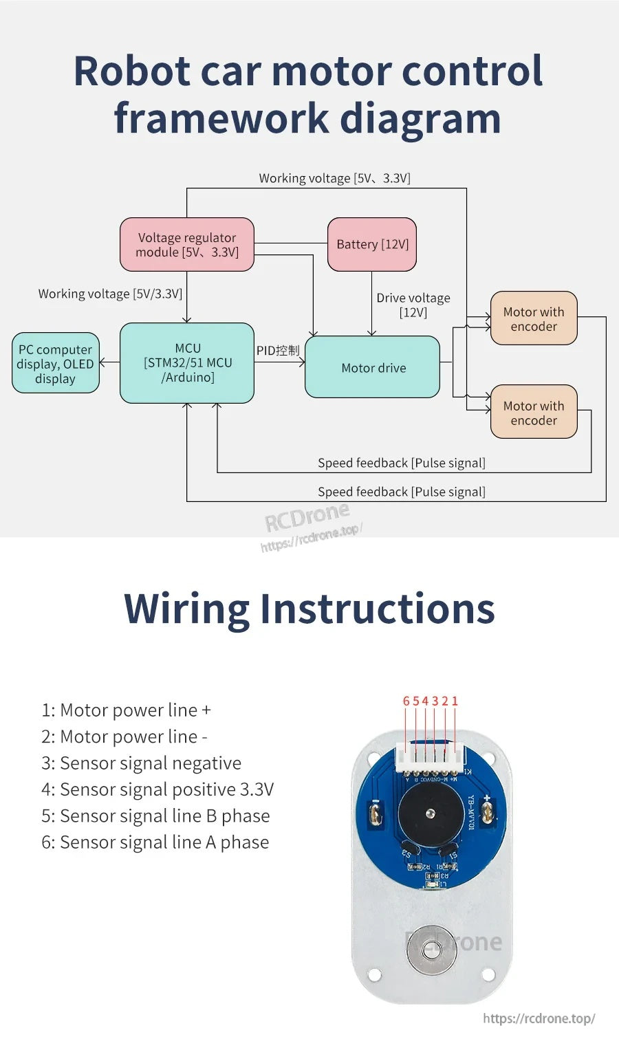
배선 가이드는 인코더 DC 감속 모터를 컨트롤러에 연결하기 위한 모터 전원, 3.3V, 접지 및 A/B 위상 피드백 신호를 라벨링합니다.
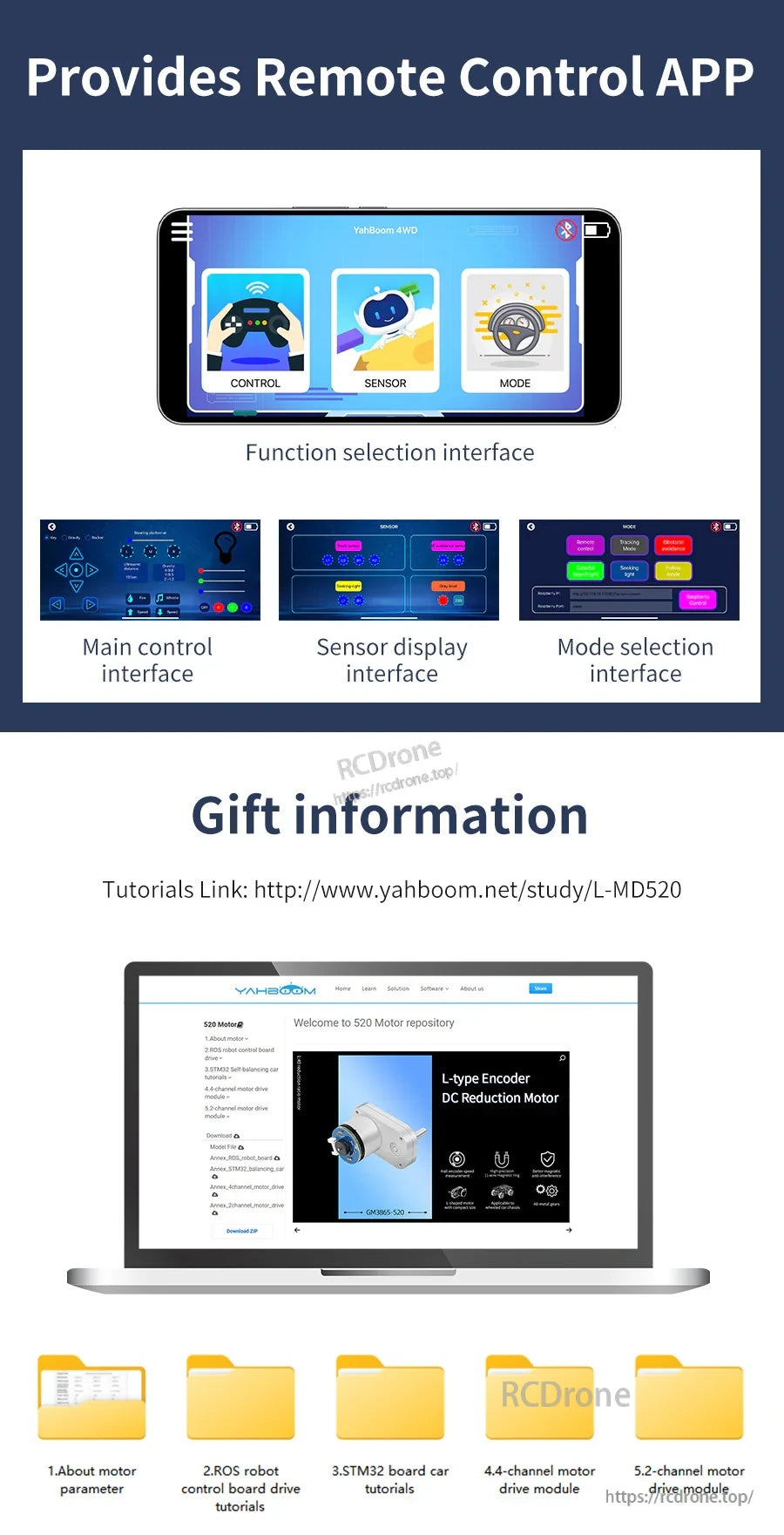
원격 제어 앱은 설정 및 작동을 위한 주요 제어 패널과 센서 디스플레이 및 모드 선택 화면을 제공합니다.
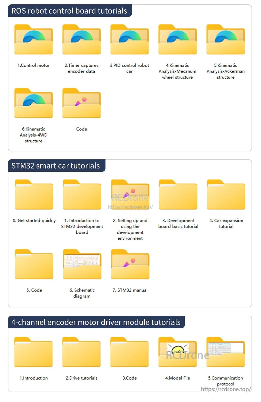
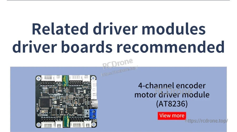
튜토리얼 폴더에는 ROS 로봇 제어 보드 가이드, STM32 스마트 카 기초 및 4채널 인코더 모터 드라이버 모듈 문서가 포함되어 있습니다.
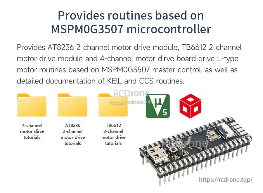
MSPM0G3507 기반 제어 루틴은 AT8236 및 TB6612 모터 드라이브 모듈에 대해 제공되며, 2채널 및 4채널 옵션이 포함됩니다.
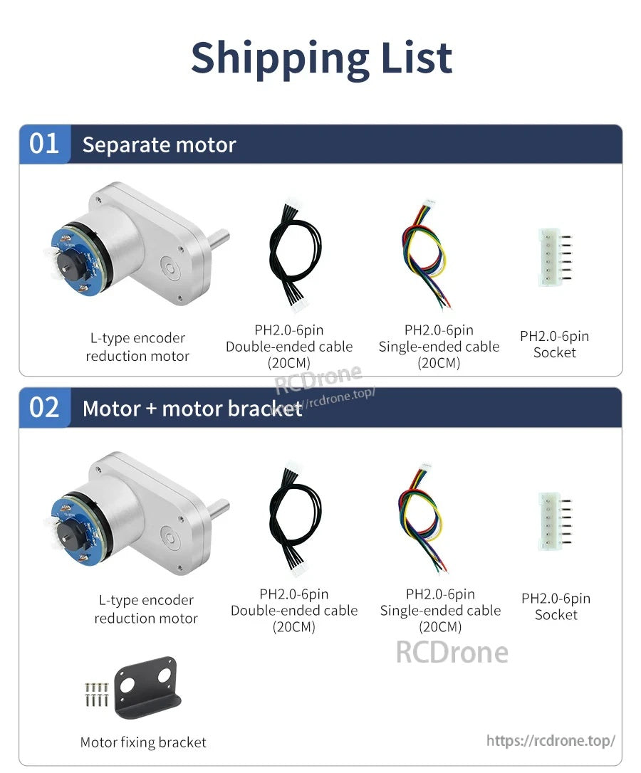
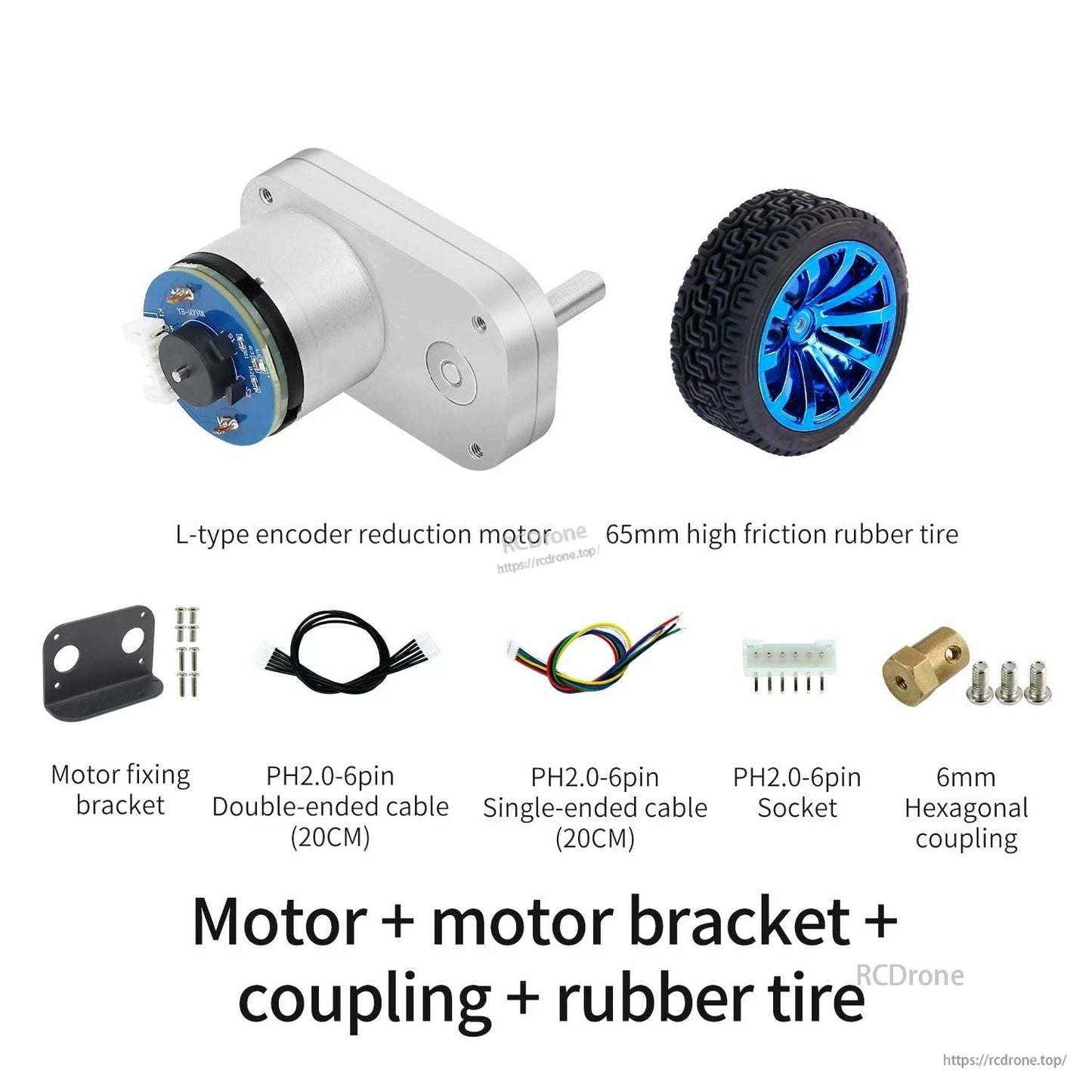
L형 인코더 감속 모터는 PH2.0 6핀 소켓과 20cm 케이블, 선택적 모터 고정 브래킷과 함께 제공됩니다.
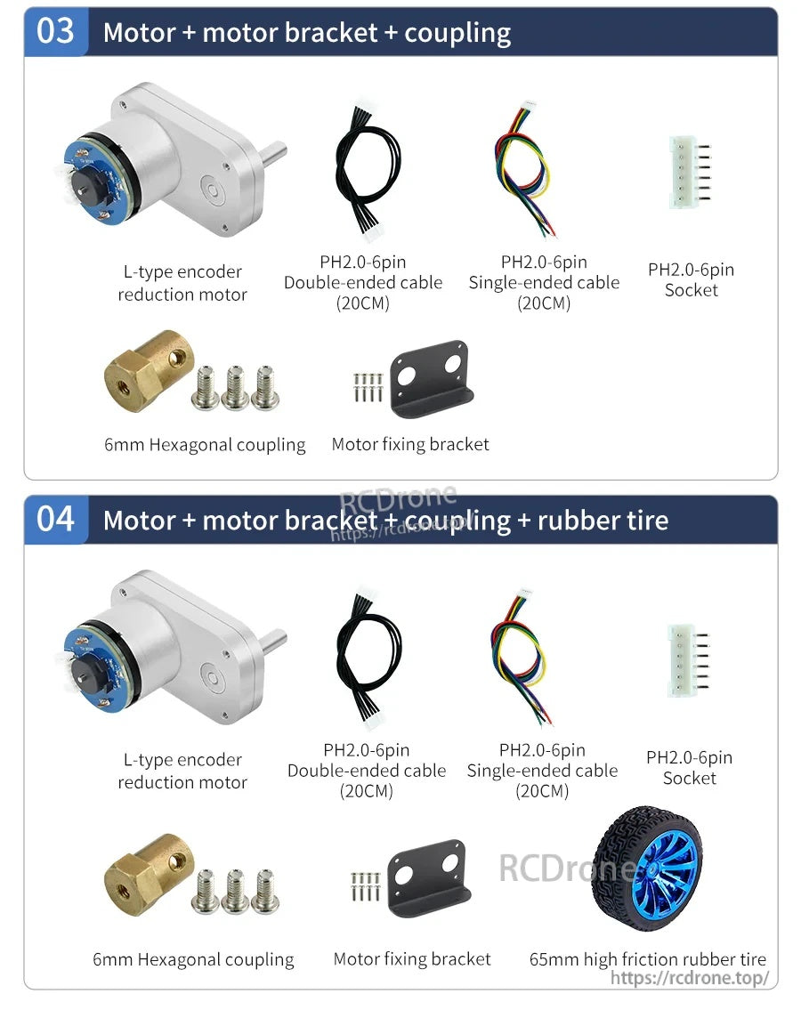
L형 520 인코더 DC 감속 모터 세트에는 모터 고정 브래킷, 6mm 육각 커플링, PH2.0-6핀 케이블 및 소켓이 포함되어 있으며, 선택 사항으로 65mm 고마찰 고무 타이어가 있습니다.