


MD520 12V 520 DC 기어 모터(엔코더 포함), 1:19/1:30/1:56, 550/333/205RPM, 밸런스 카 섀시용
MD520 12V 520 DC 기어 모터(엔코더 포함), 1:19/1:30/1:56, 550/333/205RPM, 밸런스 카 섀시용
Yahboom
픽업 사용 가능 여부를 로드할 수 없습니다.
개요
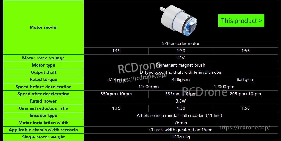
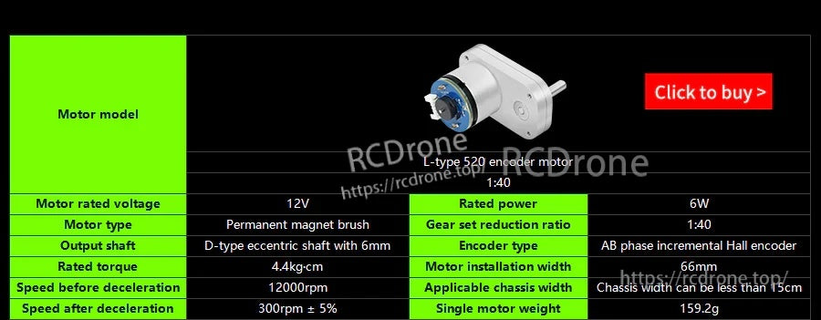
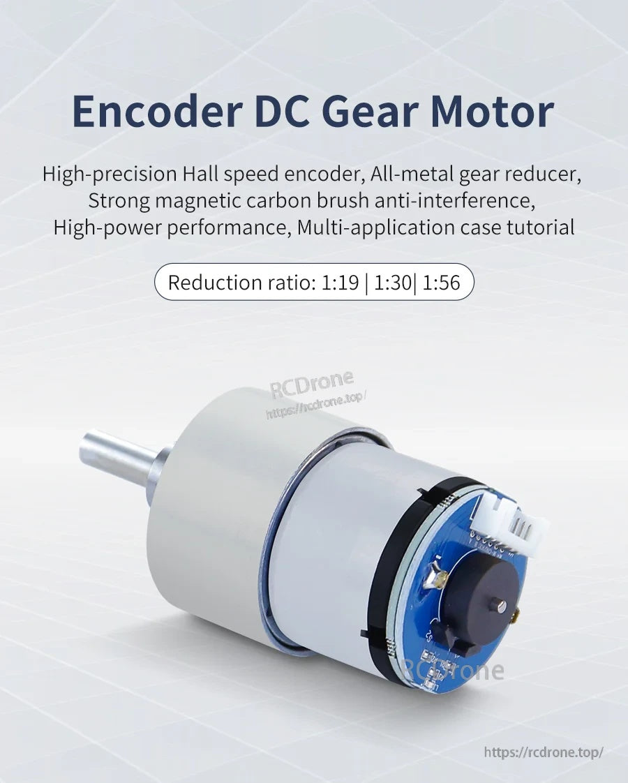
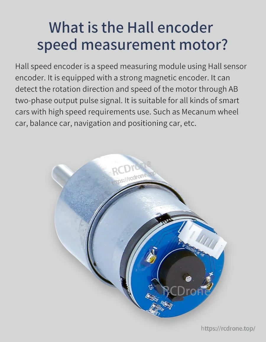
이 520 DC 기어 모터는 인코더가 장착되어 있으며, 균형차 및 4륜 카트/스마트 자동차 섀시를 위해 설계되었습니다. 속도 측정 및 방향 감지를 위해 고정밀 자기(홀) 인코더를 사용하며, 신뢰할 수 있는 구동 성능을 위해 탄소 브러시와 전금속 기어 감속기를 특징으로 합니다.
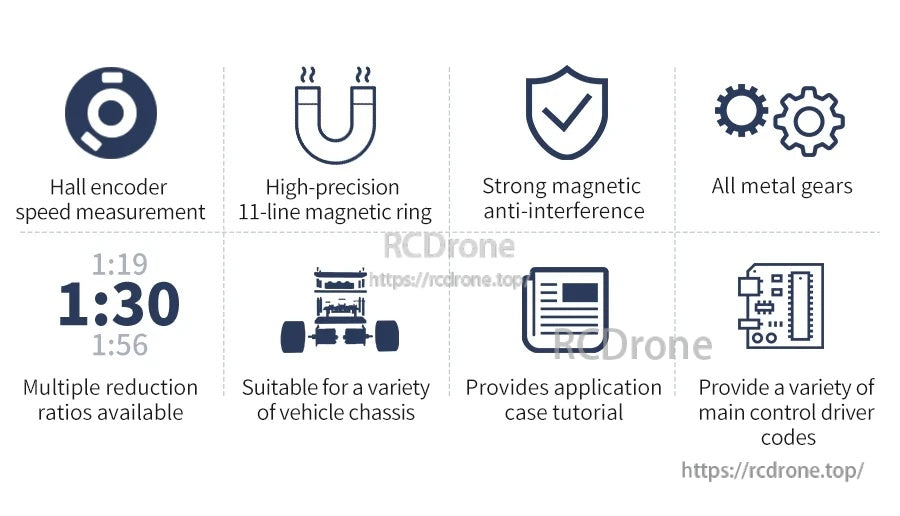
주요 특징
- 속도 측정 및 방향 감지를 위한 AB-위상 증분 홀 인코더
- 인코더는 내장된 형성 기능과 풀업 저항기를 포함하며, MCU I/O 읽기를 위한 정현파를 직접 출력합니다.
- 고정밀 11선 마그네틱 링; 강력한 자기 간섭 방지
- 전금속 기어 및 탄소 브러시 모터 구조
- 다양한 감속비 제공: 1:19 / 1:30 / 1:56
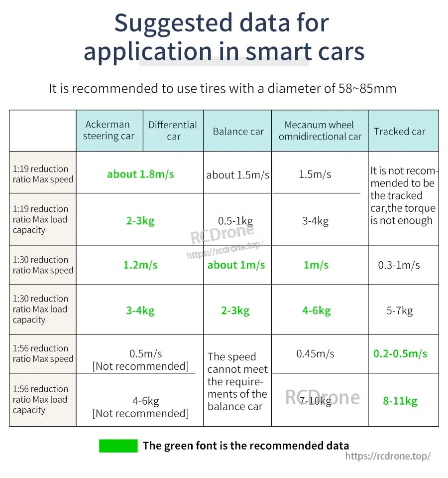
- 균형차 / 메카넘 휠 / 아커만 자동차 응용을 위한 참조 튜토리얼 언급
사양
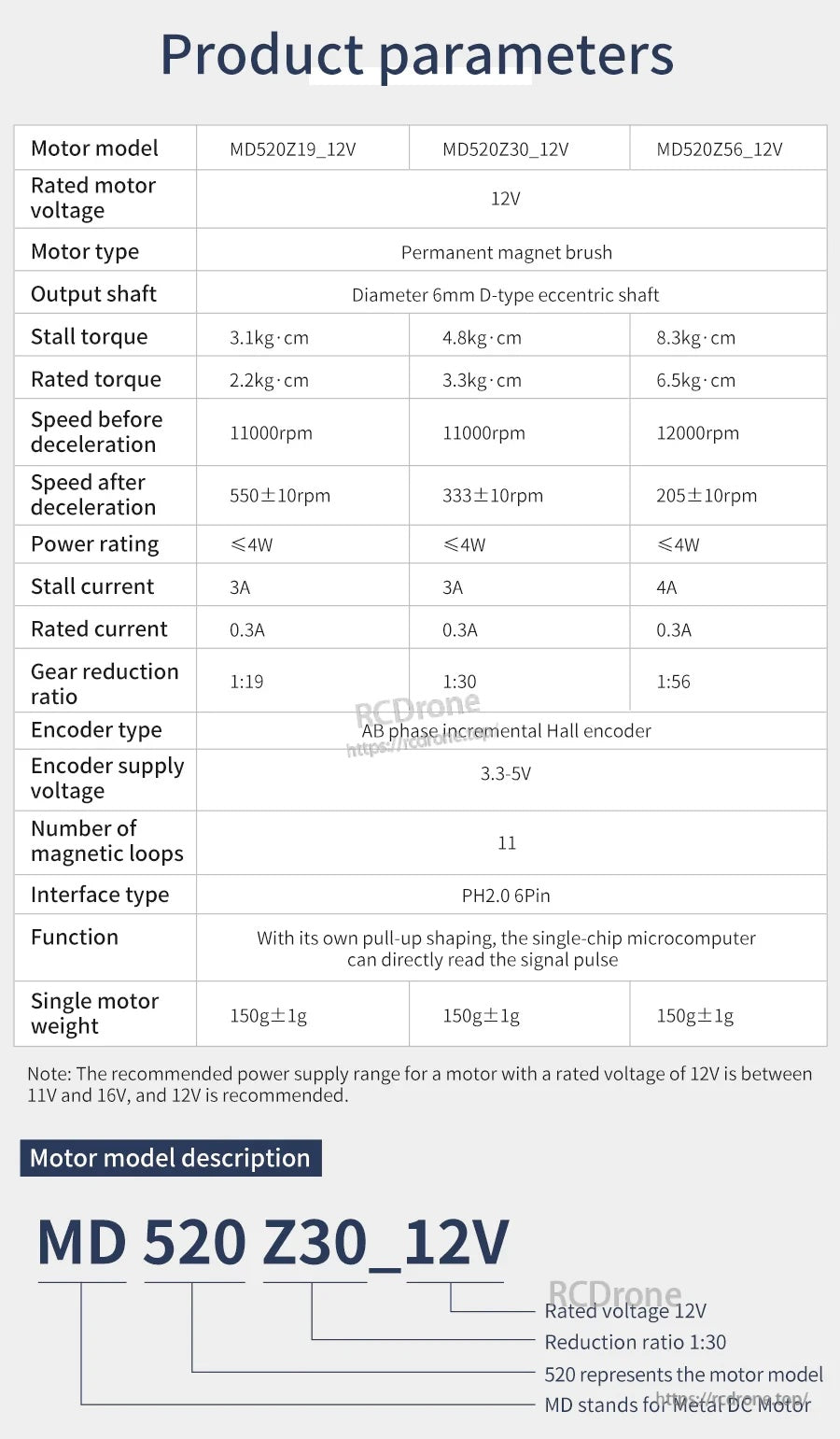
| 매개변수 | MD520Z19_12V | MD520Z30_12V | MD520Z56_12V |
|---|---|---|---|
| 정격 모터 전압 | 12V | 12V | 12V |
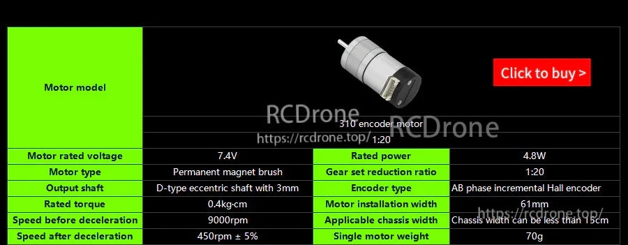
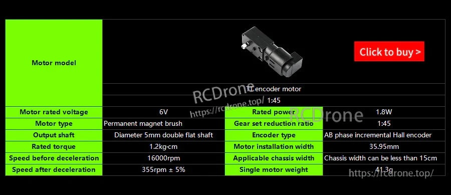
| 모터 유형 | 영구 자석 브러시 | ||
| 출력 샤프트 | 직경 6mm D형 편심 샤프트 | ||
| 정지 토크 | 3.1 kg*cm | 4.8 kg*cm | 8.3 kg*cm |
| 정격 토크 | 2.2 kg*cm | 3.3 kg*cm | 6.5 kg*cm |
| 감속 전 속도 | 11000 rpm | 11000 rpm | 12000 rpm |
| 감속 후 속도 | 550 +/- 10 rpm | 333 +/- 10 rpm | 205 +/- 10 rpm |
| 전력 정격 | <= 4W | <= 4W | <= 4W |
| 정격 전력 (표시됨) | 3.6W | ||
| 정지 전류 | 3A | 3A | 4A |
| 정격 전류 | 0.3A | 0.3A | 0.3A |
| 기어 감속 비율 | 1:19 | 1:30 | 1:56 |
| 인코더 유형 | AB 위상 증분 홀 인코더 | ||
| 인코더 전원 전압 | 3.3-5V | ||
| 자기 루프 수 | 11 | ||
| 인터페이스 유형 | PH2.0 6핀 | ||
| 기능 | 자체 풀업 형성을 통해 단일 칩 마이크로컴퓨터는 신호 펄스를 직접 읽을 수 있습니다. | ||
| 모터 설치 폭 | 76mm | ||
| 적용 가능한 섀시 폭 시나리오 (표시됨) | 섀시 폭이 15cm보다 큽니다. | ||
| 단일 모터 무게 | 150 g +/- 1 g | 150 g +/- 1 g | 150 g +/- 1 g |
전원 공급 주의 사항 (표시됨): 정격 전압이 12V인 모터의 경우, 권장 전원 공급 범위는 11V에서 16V 사이이며, 12V를 권장합니다.
인코더 출력 주의 사항 (표시됨)
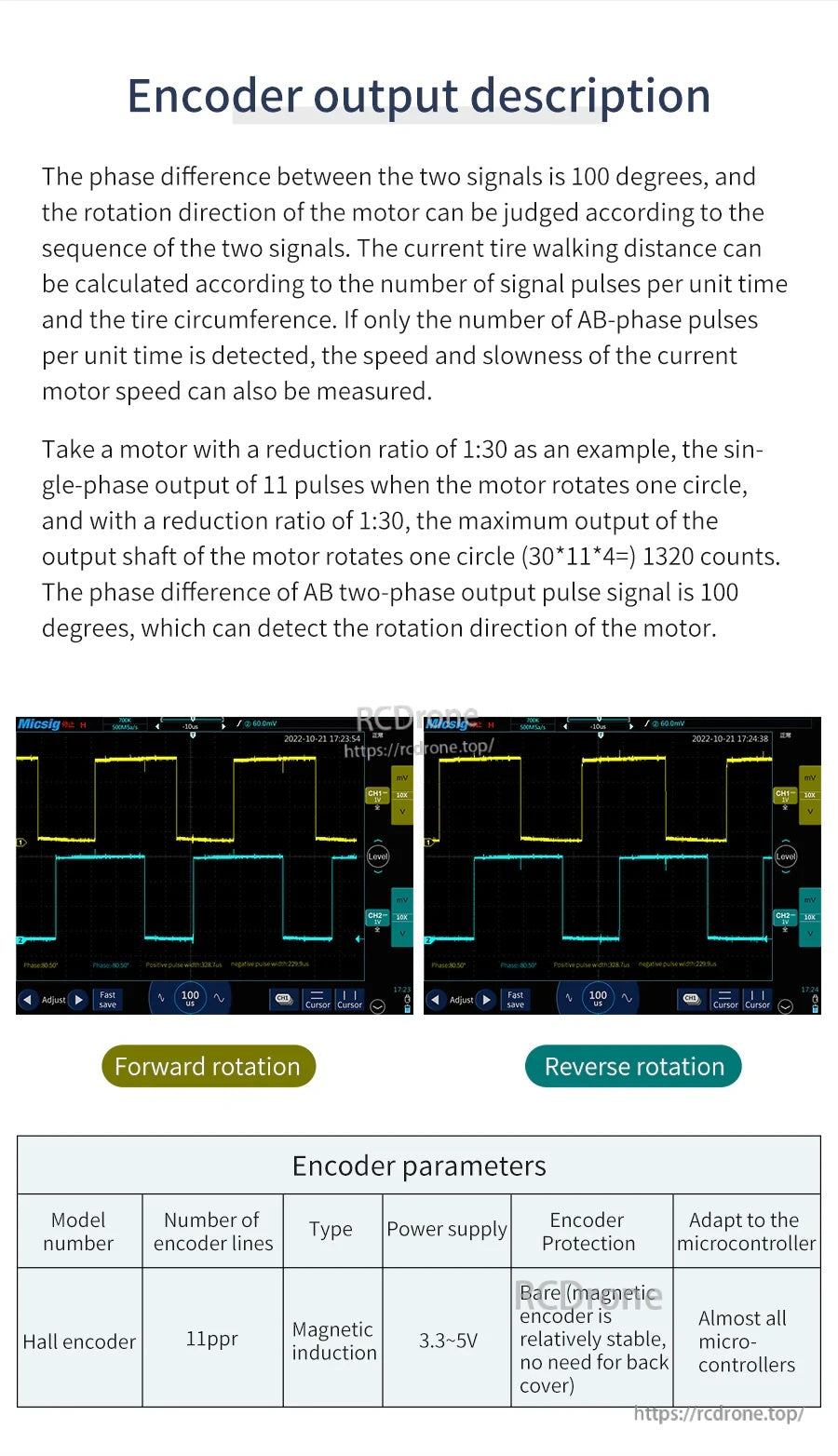
- 두 신호 간의 위상 차: 100도
- 홀 인코더: 11 ppr, 자기 유도, 전원 공급 3.3-5V
- 1:30 감속 비율에 대한 예: 단상 출력은 모터 회전당 11 펄스입니다; 회전당 최대 출력 샤프트 카운트: (30 * 11 * 4) = 1320 카운트
- 인코더 보호 노트(표시됨): 노출된 자기 인코더는 상대적으로 안정적이며, 후면 커버가 필요하지 않습니다
- 마이크로컨트롤러에 적응(표시됨): 거의 모든 마이크로컨트롤러
응용 프로그램
- 밸런스 카
- 4륜 트롤리 / 스마트 카 섀시
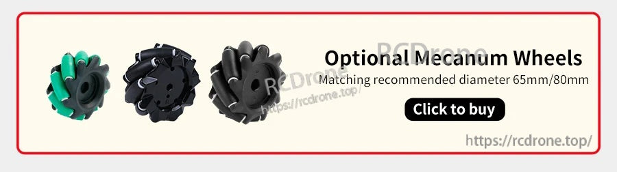
- 메카넘 휠 카
- 아커만 조향 카
- 내비게이션 및 위치 지정 카
제품 선택 및 통합 지원을 원하시면 https://rcdrone.top/에 문의하시거나 [email protected].
자세한 내용

인코더 준비가 된 520 기어 모터로 스마트 카 및 밸런스 카 빌드에서 신뢰할 수 있는 속도 및 방향 피드백을 받으세요.
속도와 토크의 균형을 맞추기 위해 1:19, 1:30 또는 1:56 감속을 선택하세요.
고정밀 홀 인코더가 전금속 기어박스와 결합되어 하중 하에서도 제어 루프를 안정적으로 유지합니다.
전체 매개변수 표에는 정지/정격 토크, 출력 RPM, 전류 및 3.3–5V 인코더 전원 범위가 나열되어 있습니다.
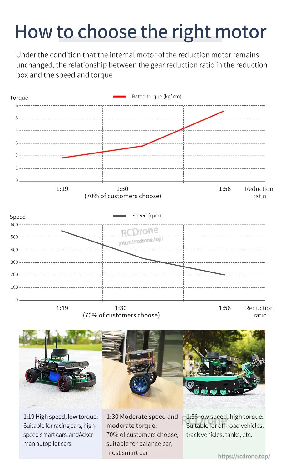
비율 곡선을 사용하여 차량에 대해 더 높은 속도(1:19) 또는 더 높은 토크와 더 세밀한 제어(1:56)를 선택하십시오.
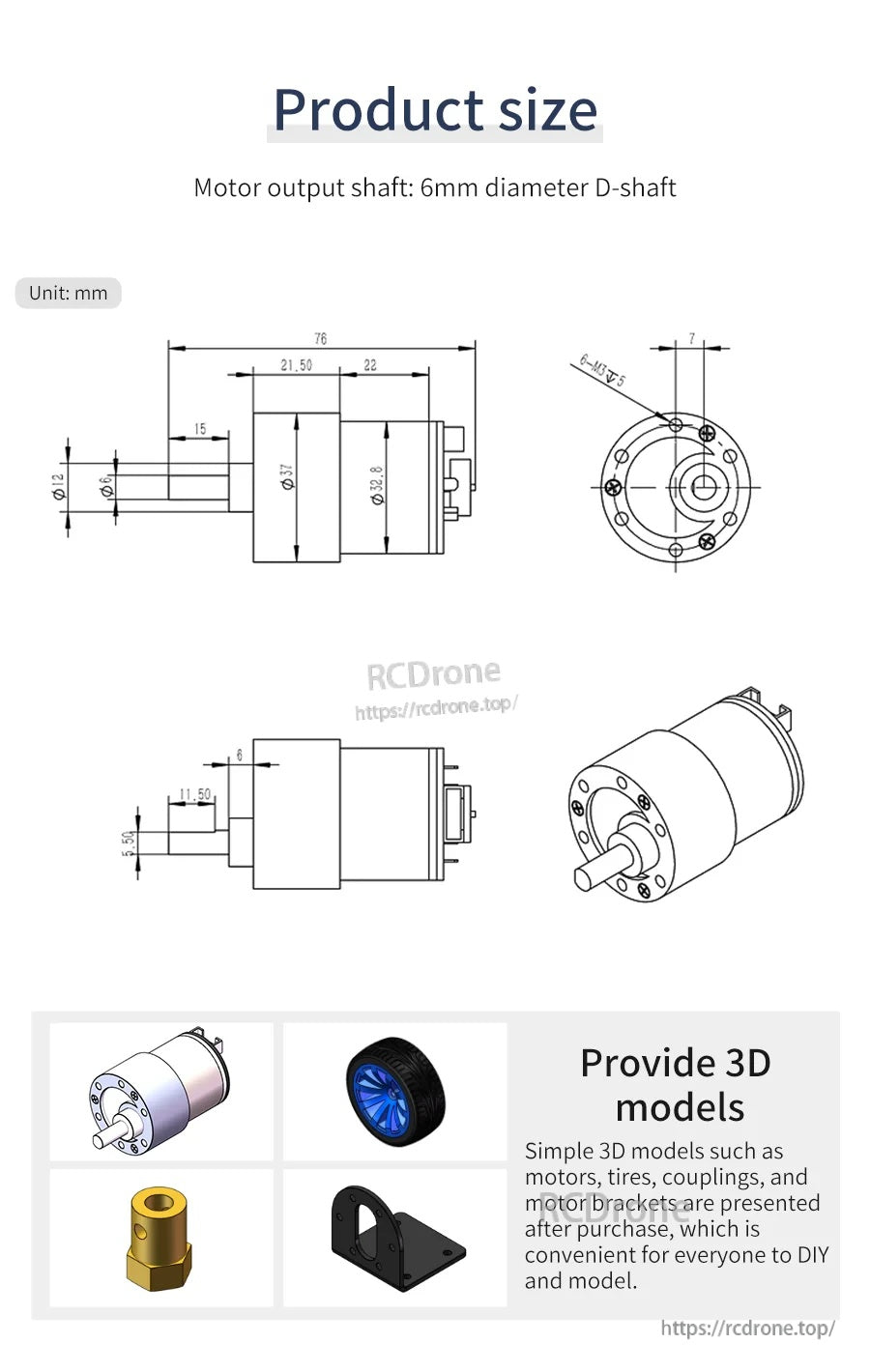
기계 도면은 6mm D-샤프트 출력 및 장착 치수를 포함하여 장착 확인에 도움이 됩니다.
AB-상태 정사각형 파형 출력은 대부분의 마이크로컨트롤러가 방향과 속도를 쉽게 읽을 수 있도록 합니다.

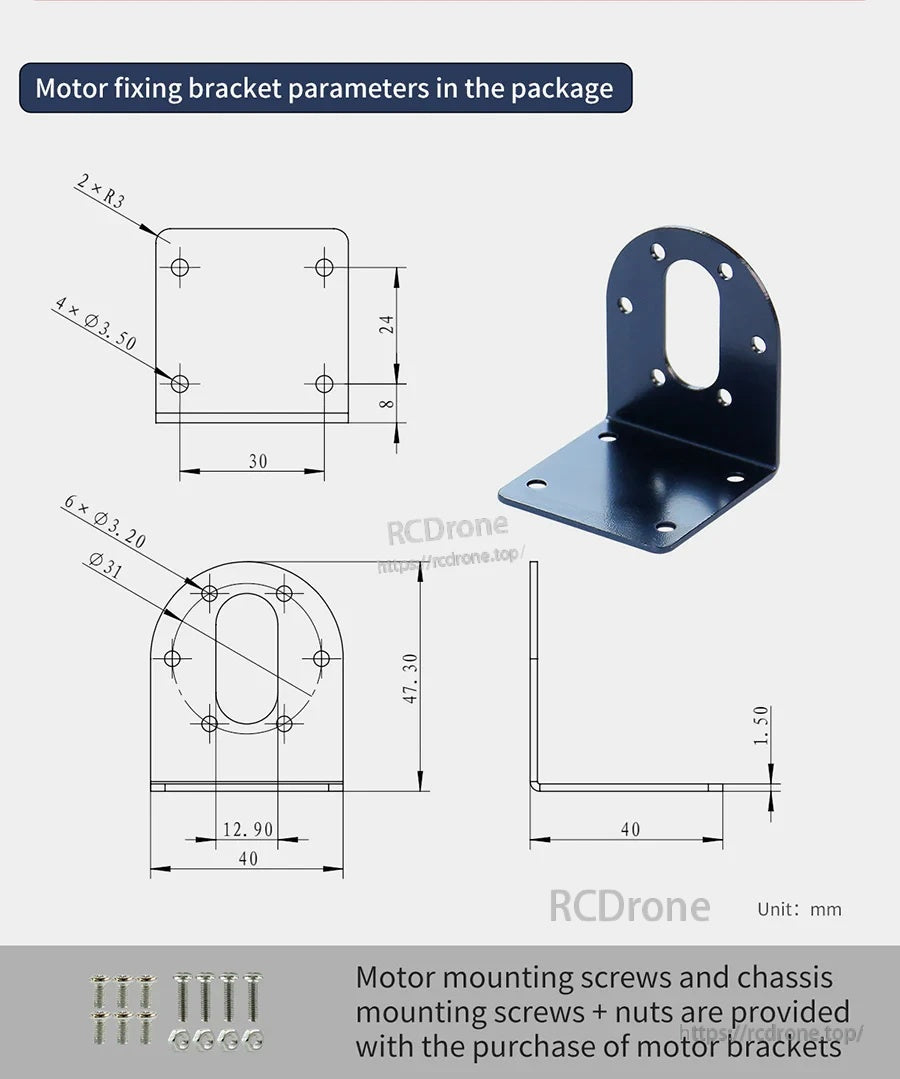
장착 브래킷 치수가 더 쉬운 섀시 레이아웃을 위해 제공되며, 일치하는 패스너도 사용할 수 있습니다.
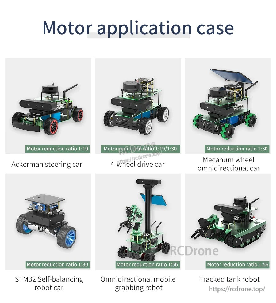
일반적인 플랫폼 예로는 아커만 조향, 4WD, 메카넘 드라이브, 자가 균형 로봇 및 트랙 빌드가 있습니다.

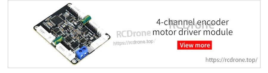
4채널 인코더 모터 드라이버 모듈은 여러 인코더 장착 DC 모터를 연결하고 제어하는 컴팩트한 방법을 제공합니다.
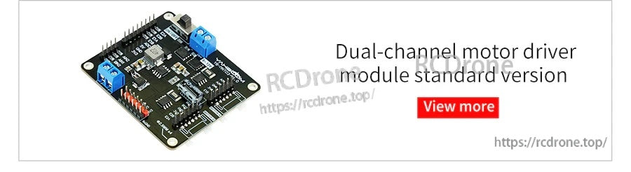
스크류 단자와 핀 헤더가 있는 듀얼 채널 모터 드라이버 모듈은 두 개의 DC 모터에 대한 배선을 간소화하는 데 도움을 줍니다.
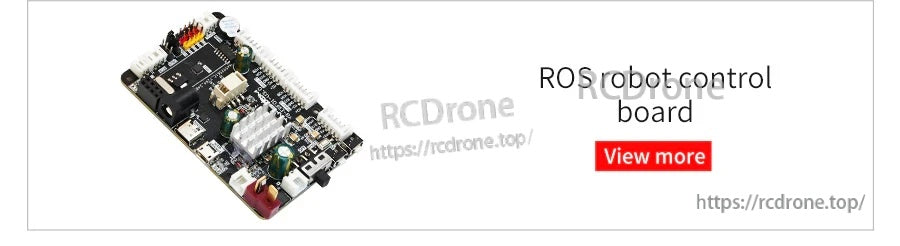
ROS 로봇 제어 보드는 히트싱크와 여러 커넥터가 포함된 컴팩트한 PCB 레이아웃을 제공하여 로봇 빌드에 쉽게 통합할 수 있습니다.
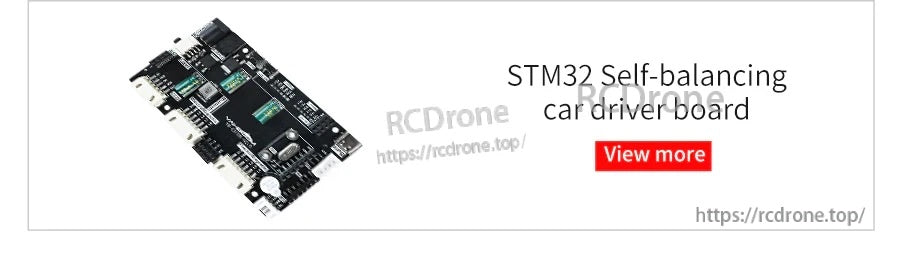
STM32 자가 균형 자동차 드라이버 보드는 균형 자동차 설정을 위한 배선에 여러 커넥터가 있는 컴팩트한 제어 PCB를 제공합니다.
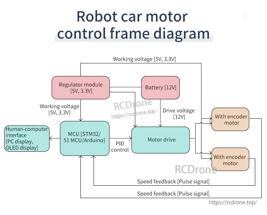
12V 배터리는 모터 드라이버와 인코더 모터에 전원을 공급하며, 레귤레이터는 MCU에 PID 속도 제어 및 펄스 피드백을 위한 5V/3.3V 전원을 공급합니다.
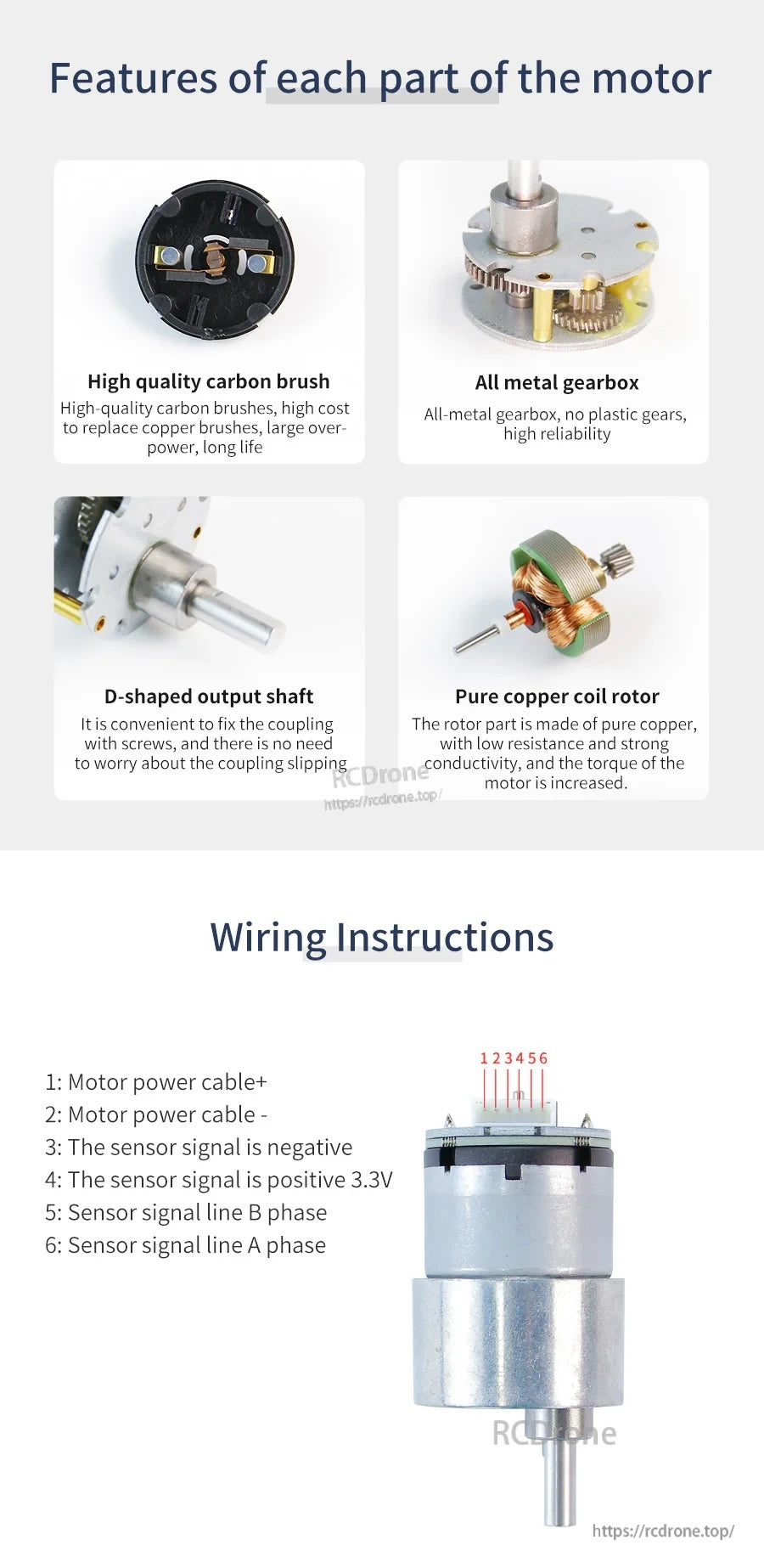
MD520 DC 기어 모터의 세부 사항에는 전금속 기어박스, D자형 출력 샤프트, 탄소 브러시 및 모터 전원 및 센서 신호 라인이 포함된 6핀 커넥터가 포함됩니다.
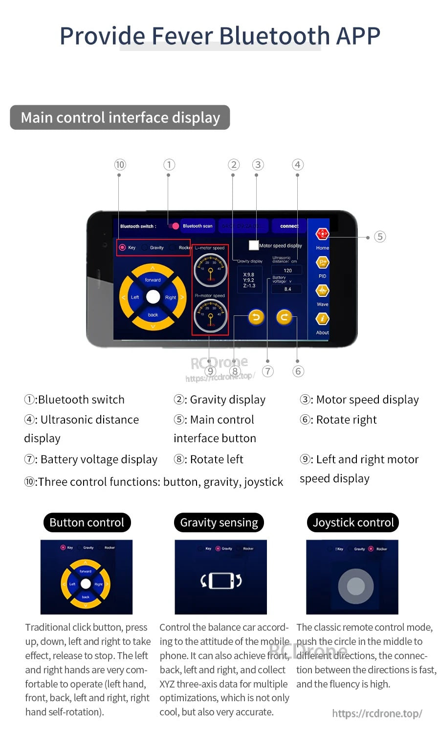
피버 블루투스 앱은 버튼, 중력 감지 및 조이스틱 제어 옵션을 제공하며, 화면에 모터 속도 및 배터리 전압을 표시합니다.
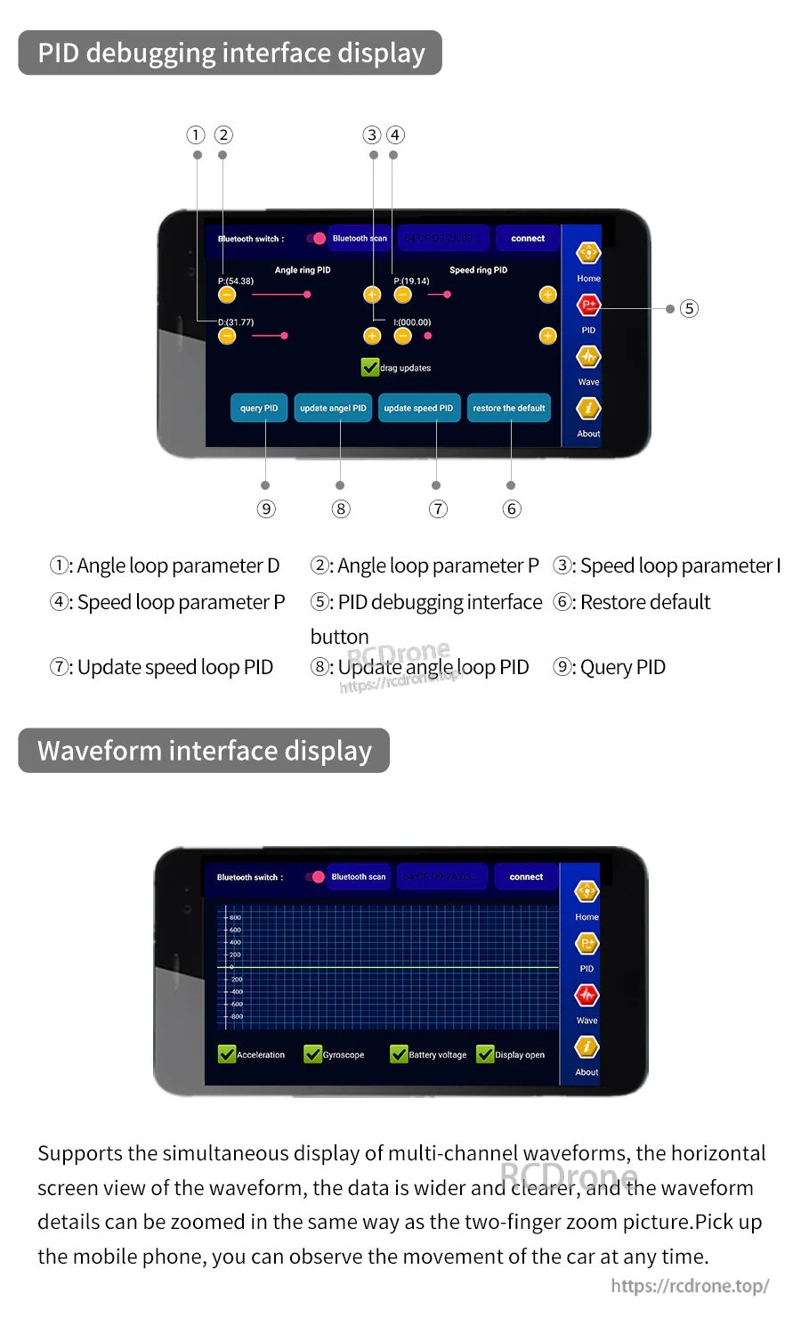
PID 조정 화면은 각도 및 속도 루프 매개변수 제어와 함께 다채널 파형 보기 및 블루투스 연결을 제공합니다.

블루투스 제어 및 관련 문서를 갖춘 오픈 소스 개발자 앱은 스마트 자동차 개발 및 조정을 지원합니다.
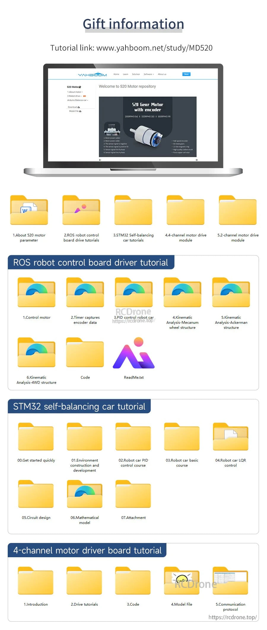
MD520 지원 파일에는 ROS 로봇 제어, STM32 자가 균형 자동차 프로젝트 및 4채널 모터 드라이버 보드를 위한 드라이버 및 튜토리얼 폴더가 포함되어 있습니다.
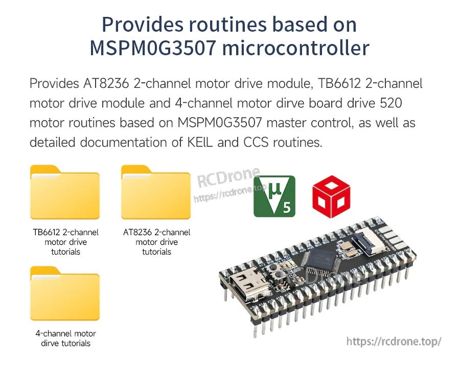
MSPM0G3507 기반 루틴은 AT8236 및 TB6612 모터 드라이브 모듈을 지원하며, 모터 제어 프로젝트를 위한 KEIL 및 CCS 코드 문서가 포함되어 있습니다.
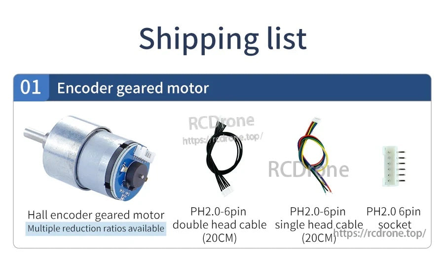
MD520 인코더 기어드 모터 패키지에는 20cm PH2.0 6핀 단일 및 이중 헤드 케이블과 배선을 위한 일치하는 6핀 소켓이 포함되어 있습니다.
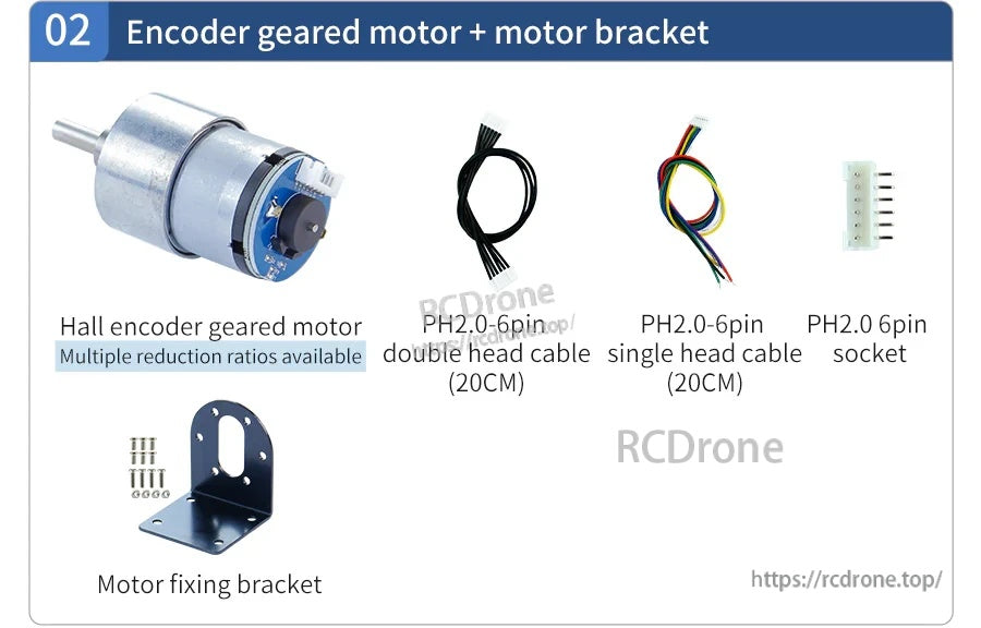
MD520 인코더 기어 모터 키트에는 메탈 장착 브래킷과 PH2.0 6핀 케이블 옵션 및 깔끔한 배선을 위한 일치하는 소켓이 포함되어 있습니다.
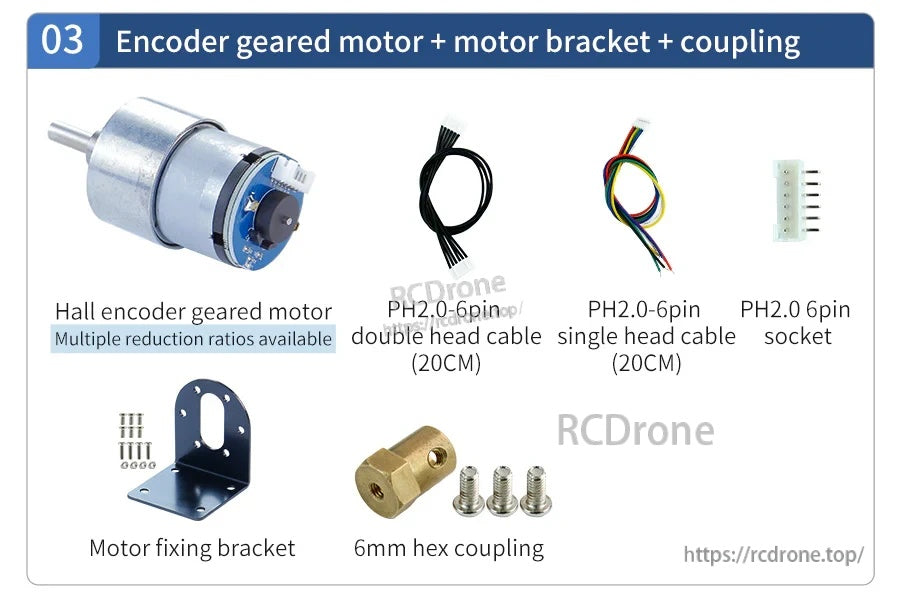
인코더 기어드 모터 키트에는 모터 고정 브래킷, 6mm 육각 커플링, 배선을 위한 PH2.0 6핀 케이블 및 소켓이 포함되어 있습니다.
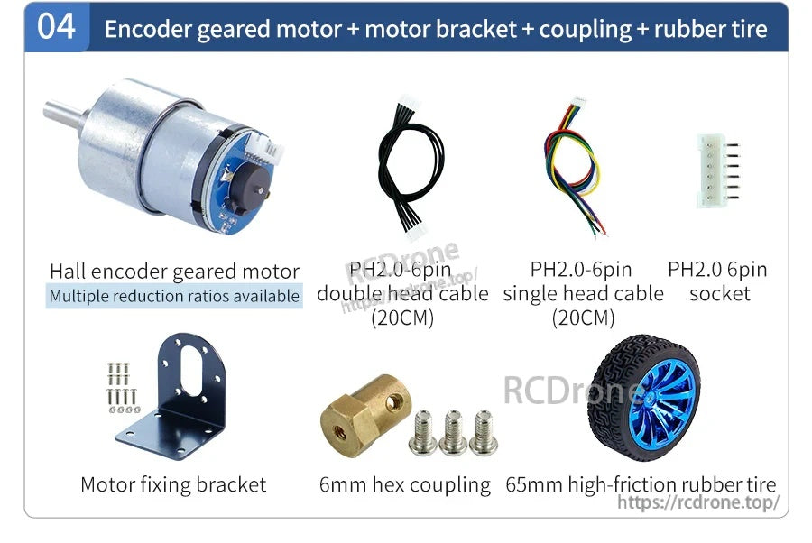
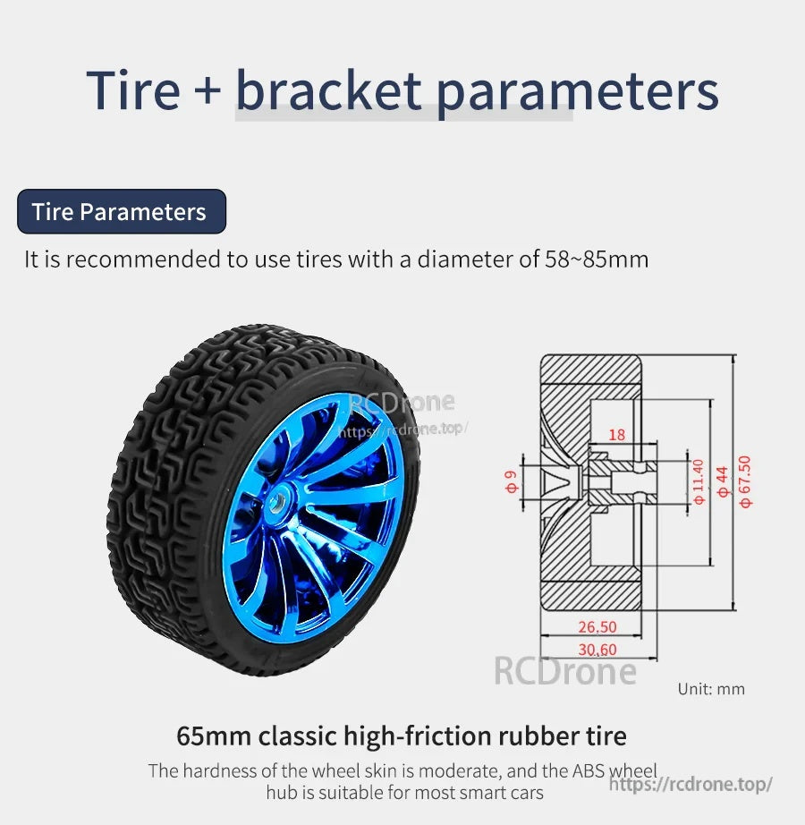
MD520 12V DC 기어 모터 키트에는 홀 인코더 모터, 모터 고정 브래킷, 6mm 육각 커플링, PH2.0 인코더 케이블, 소켓 및 섀시 빌드를 위한 고마찰 고무 타이어가 포함되어 있습니다.


