


BETAFPV F4 2-3S 20A AIO Flight Controller V1, Serial ELRS 2.4G, 9V/5V BEC, DJI O3 6-Pin PMU
BETAFPV F4 2-3S 20A AIO Flight Controller V1, Serial ELRS 2.4G, 9V/5V BEC, DJI O3 6-Pin PMU
BETAFPV
Couldn't load pickup availability
Overview
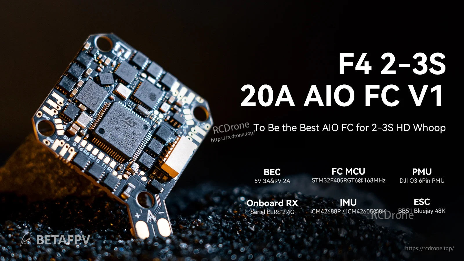
The BETAFPV F4 2-3S 20A AIO FC V1 is an AIO flight controller designed for HD digital VTX builds using 2-3S batteries. It combines a 20A ESC with a dual BEC solution (9V@2A for DJI O3 and 5V@3A for external devices) to help maintain stable power during throttle changes. It also features a DJI O3 6-pin PMU connector for solder-free installation and a rear SH1.0 4-pin USB port for tuning and maintenance.
Key Features
- Input voltage: 2-3S
- Dual BEC outputs: 9V@2A (DJI O3) and 5V@3A (external devices)
- DJI O3 6-pin PMU for easier HD VTX installation (no soldering for the connector)
- Built-in ESC: 20A continuous, 25A peak; signal support D-shot300 / D-shot600
- MCU: STM32F405RGT6 @ 168MHz
- Onboard receiver: Serial ELRS 2.4G (CRSF protocol)
- IMU (SPI): ICM42688P / ICM42605 (graphic notes show “@8K”)
- 16MB blackbox; barometer; voltage & current sensing
- USB port relocated to the rear (SH1.0 4-pin)
- UART3 can be released (TX3/RX3) and onboard RX power can be cut off via hardware modifications described below
Specifications
| Weight | 5.58g (without motor connectors and power cable); 5.92g (with motor connectors) |
| Mounting hole size | 26mm x 26mm |
| CPU | STM32F405RGT6 (168MHz) |
| Six-axis IMU (SPI) | ICM42688P / ICM42605 |
| Receiver (RX) | Serial ELRS 2.4G Receiver |
| RX firmware version | BETAFPV AIO 2400 RX ELRS V3.3.0 |
| Antenna | Enameled wire |
| Blackbox memory | 16MB |
| Sensors | Barometer (BMP280 / DSP310); Voltage & Current |
| 5V BEC | 5V 3A@8V supply * |
| 9V BEC | 9V 2A@8V supply * |
| USB port | SH1.0 4-pin |
| Built-in ESC current | 20A continuous; peak 25A |
| ESC input voltage | 2-3S |
| FC firmware version | Betaflight_4.4.1_BETAFPVF405 |
| ESC firmware | C_X_70_48_V0.19.2.hex (BB51 Bluejay hardware) |
| ESC signal support | D-shot300, D-shot600 |
* The output current of BEC will decrease as the temperature increases.
Wiring / Pinout Highlights (from board diagrams)
- Battery pads: Batt+ (2-3S), Batt-
- HD digital VTX port (connector); VCC note shown: 9V (Default) / 5V
- I2C pads: SCL, SDA
- UART pads shown: T1/R1, T6/R6, TX3/RX3, TX4/RX4; SBUS pad also shown
- Buzzer pads: BUZZ+ and BUZZ-; LED pads shown
- Barometer marking: BMP280/DSP310
- Receiver-related markings shown: SX1280/SX1281, ESP8285, WiFi antenna, RX LED (Green), FC LED (Blue)
- Bottom diagram markings: FC/Receiver BOOT button, RGB LED 1 / RGB LED 2, 5V BEC, onboard current sensor
- USB pads shown on bottom diagram: D-, D+, GND, USB 5V
- ESC MCU marking shown on bottom diagram: EFM8BB51 (FW C_X_70); “20A MOS” shown around ESC areas; ESC1/ESC2/ESC3/ESC4 labels
Setup Notes (text shown in wiring graphic)
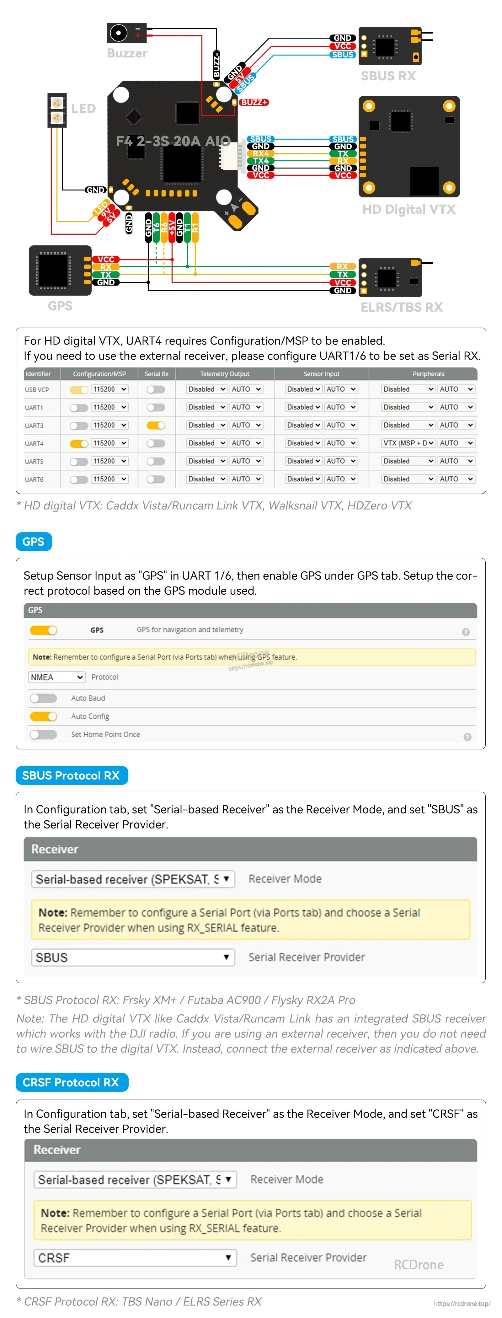
- For HD digital VTX, UART4 requires Configuration/MSP to be enabled.
- If an external receiver is used, configure UART1/6 to be set as Serial RX.
- GPS: set Sensor Input as “GPS” in UART1/6, then enable GPS under the GPS tab and select the correct protocol for the GPS module.
- SBUS protocol RX: set Receiver Mode to “Serial-based Receiver” and set Serial Receiver Provider to “SBUS”.
- CRSF protocol RX: set Receiver Mode to “Serial-based Receiver” and set Serial Receiver Provider to “CRSF”.
- HD digital VTX examples shown: Caddx Vista / Runcam Link VTX, Walksnail VTX, HDZero VTX.
- SBUS protocol RX examples shown: Frsky XM+ / Futaba AC900 / Flysky RX2A Pro.
- CRSF protocol RX examples shown: TBS Nano / ELRS Series RX.
- Note shown: some HD digital VTX units may include an integrated SBUS receiver (works with DJI radio). When using an external receiver, SBUS wiring to the digital VTX may not be required.
FAQ / Hardware Options
- Power cutoff: Removing the chip bead disconnects the power supply; to reuse the onboard ELRS receiver, solder the solder pads together to restore power.
- UART3 release: Removing two resistors on the solder pads releases UART3 (left: TX3, right: RX3). To reconnect, solder the solder pads together when reusing the onboard ELRS receiver.
- Voltage switch (HD VTX connector): The default voltage for the HD VTX connector is 9V. To use WalkSnail Avatar HD mini 1s and Lite, ensure the power supply is 5V by moving the chip bead from the 9V position to the 5V position (or use solder instead of the chip bead to switch between 5V and 9V pads).
- Motor choice note: Avoid motors above 20,000KV.
Firmware / Downloads
For build, wiring, or firmware questions, contact https://rcdrone.top/ or [email protected].
- FC firmware (STM32F405 version): Betaflight_4.4.1_BETAFVF405
- Firmware & CLI dump download: https://support.betafpv.com/hc/en-us/articles/21884915967513-CLI-for-F4-2-3S-20A-Flight-Controller-ELRS-V1-0-
- Betaflight 4.4.1 release: https://github.com/betaflight/betaflight/releases/tag/4.4.1
ESC Firmware Notes
- BB51 ESC solution based on BLHeliSuite16714903 with Bluejay ESC firmware.
- Supports bidirectional D-shot and RPM filtering in Betaflight.
- PWM frequency options: 24kHz, 48kHz, 96kHz; default factory setting: 48kHz.
- 96kHz is not recommended in the provided notes due to possible motor idle setting issues.
- Provided warning: do not flash the firmware with a shorter interval, as it may cause stalling and damage to the flight controller.
- ESC-Configurator: https://preview.esc-configurator.com/
- BLHeliSuite16714903: https://github.com/4712/BLHeliSuite/releases/tag/16714903
- Bluejay firmware releases: https://github.com/bird-sanctuary/bluejay/releases (note shown: choose C_X_70.HEX)
Serial ELRS 2.4G RX (binding & update notes)
- Uses CRSF protocol between receiver and flight controller.
- Enter binding status by power on/off three times (plug in and unplug the flight controller three times).
- Bind mode indication: RX LED quick double blink; bound: solid light.
- Receiver update methods noted: Wi-Fi or Betaflight serial passthrough.
- Passthrough update notes shown: plug in FC to computer, do not connect to Betaflight Configurator; choose target “BETAFPV 2.4GHz AIO RX”; flash using Betaflight Passthrough in ExpressLRS Configurator.
- Firmware flashing guide: https://support.betafpv.com/hc/en-us/articles/4404231679129-How-to-Flash-Firmware-of-ELRS-RX-TX
What’s Included
- 1 x F4 2-3S 20A AIO FC V1
- 4 x M2*10 machine screw
- 4 x M2*10 nylon screw
- 4 x M2 nuts
- 4 x shock absorbing ball
- 4 x JST1.25mm angle socket
- 4 x JST1.25mm straight socket
- 1 x SH1.0 4-pin adapter cable
- 1 x Type-C to SH1.0 adapter
- 1 x XT30 power cord
- 1 x filter capacitor
- 1 x 30mm double-head VTX connector wire
- 1 x 60mm single-head VTX connector wire
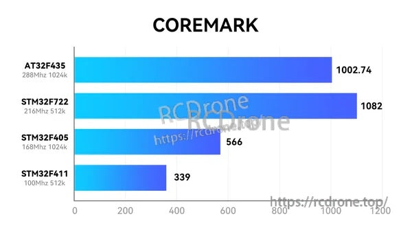
Reference (CoreMark chart shown in product graphic)
| AT32F435 (288MHz 1024k) | 1002.74 |
| STM32F722 (216MHz 512k) | 1082 |
| STM32F405 (168MHz 1024k) | 566 |
| STM32F411 (100MHz 512k) | 339 |
Details
A compact 2–3S AIO solution that pairs an F4 flight controller with a 20A ESC for HD whoop-style builds.

Clear top-side pad map helps identify the DJI digital VTX connector, battery pads, UARTs, and buzzer/LED connections before soldering.
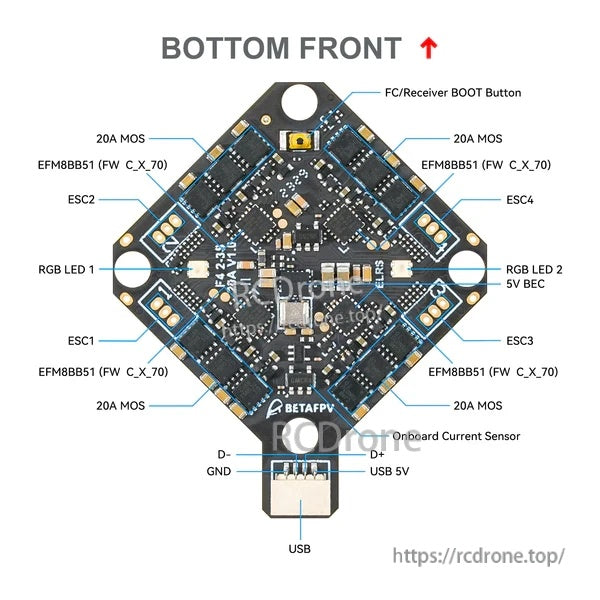
The underside layout highlights the ESC sections, boot button, RGB LED pads, onboard current sensor, and USB wiring points.
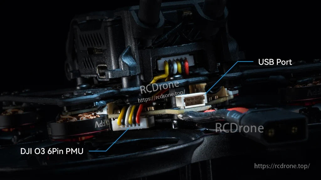
A rear-mounted USB port and the DJI O3 PMU connector keep wiring tidy on compact frames.


The HD VTX connector ships set to 9V by default, with an alternate 5V option available via a small solder change.

A wiring example and Betaflight receiver settings guide simplify setup for digital VTX builds and serial receiver configuration.

Related Collections


