HD LINK V2 Fiber Optic Transmission Module FPV Digital Video System, 1080p HDMI x2, 0–80km, SBUS/CRSF
HD LINK V2 Fiber Optic Transmission Module FPV Digital Video System, 1080p HDMI x2, 0–80km, SBUS/CRSF
OddityRC
Couldn't load pickup availability
Overview
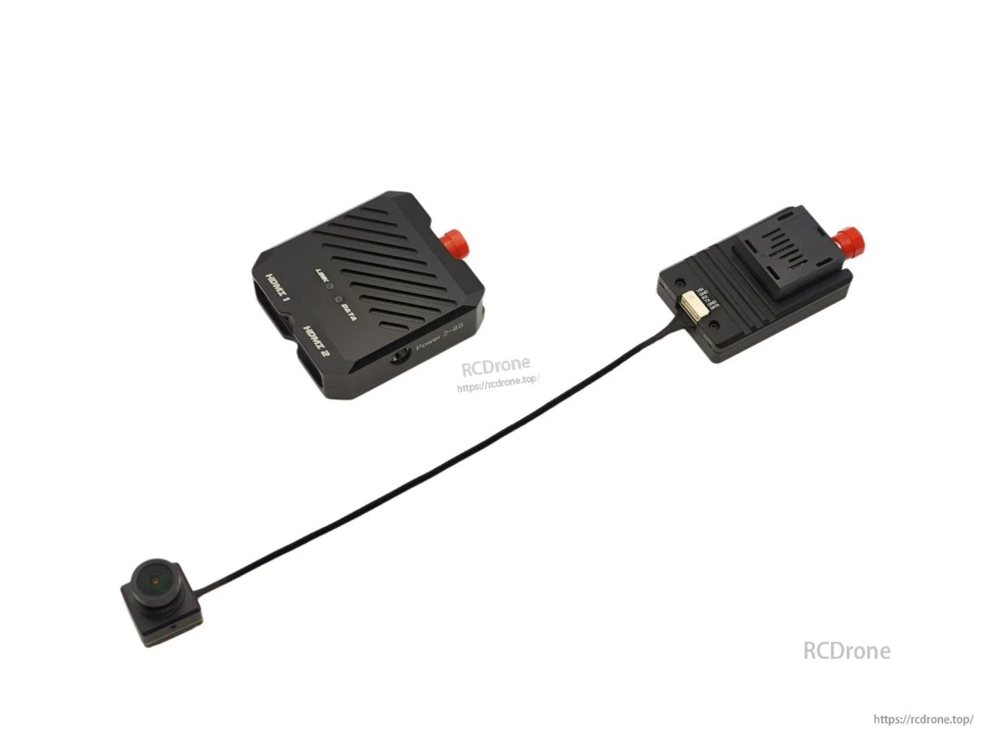
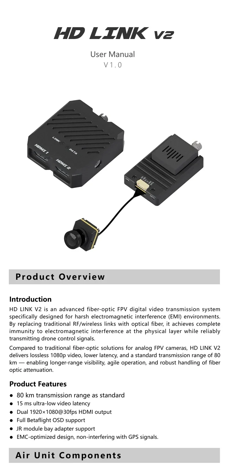
HD LINK V2 is a fiber optic transmission module (fiber-optic FPV digital video transmission system) designed for harsh electromagnetic interference (EMI) environments. By replacing traditional RF/wireless links with optical fiber, it provides high immunity to electromagnetic interference at the physical layer while transmitting drone control signals. It supports 1080p video, low latency, and a standard transmission range of 80 km.
Key Features
- Standard transmission range: 80 km
- Video latency: 15 ms (ultra-low)
- Dual HDMI output (feature text: 1920x1080@30fps)
- Full Betaflight OSD support
- JR module bay adapter support
- EMC-optimized design, non-interfering with GPS signals
Interfaces & Components
Air Unit Components (diagram labels)
- Camera
- MIPI coaxial cable
- Link status LED
- RC signal LED
- 3-in-1 interface
- Air unit main body
- Fiber optic port
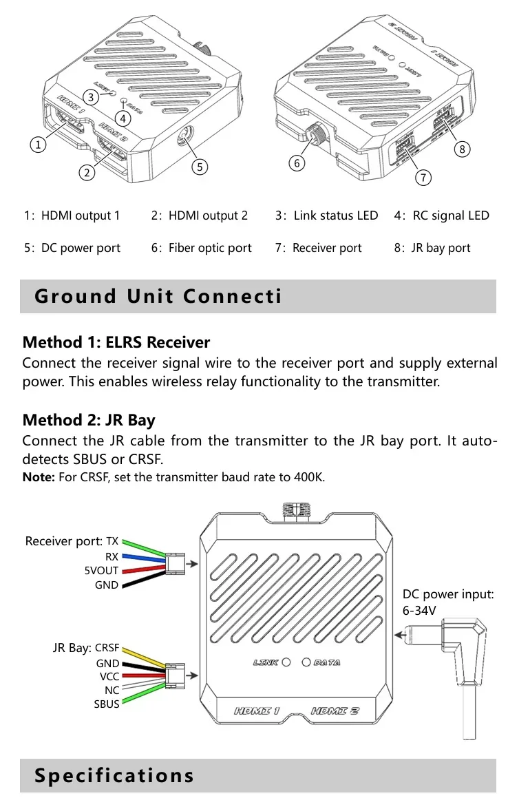
Ground Unit Components (diagram labels)
- HDMI output 1
- HDMI output 2
- Link status LED
- RC signal LED
- DC power port
- Fiber optic port
- Receiver port
- JR bay port
Wiring & Setup
Air Unit Connection (3-in-1 port)
The 3-in-1 port integrates power supply, OSD output, and RC signal reception.
- SBUS mode: Plug the 3-in-1 cable directly into the flight controller’s “DJI” port (no soldering required).
- CRSF mode: Connect the TX wire (yellow) from the 3-in-1 cable to the flight controller’s RX pin.
3-in-1 cable pinout
- Pin1 (Yellow): Signal TX
- Pin2 (Brown): GND
- Pin3 (Green): UART TX → FC OSD RX (0–3.3 V)
- Pin4 (Blue): UART RX → FC OSD TX (0–3.3 V)
- Pin5 (Black): Power GND
- Pin6 (Red): Power (7–34 V)
Flight Controller OSD Set
Method 1: Betaflight Configurator (recommended)
Connect the video transmitter’s OSD serial port to the flight controller to obtain OSD information (example uses Betaflight Configurator 10.10.0 and firmware 4.5.0 for UART setup).
- Connect the green (UART_TX) and blue (UART_RX) wires from the 6-pin 3-in-1 cable to the flight controller’s UART1 port (UART1 used as an example).
- In Betaflight Configurator, open the Ports tab, select the corresponding UART port, enable MSP, and set VTX (MSP + Displayport).
- On the Presets page, search for HD OSD and select it.
- On the OSD page, configure the information to display.
Method 2: CLI Command Line Setup
- Open the corresponding UART port (UART1 example), enable MSP, click Save, and set VTX (MSP + Displayport).
- Open the CLI and enter:
set osd_displayport_device = MSP
set vcd_video_system = HD
save
Ground Unit Connection
- Method 1: ELRS Receiver — Connect the receiver signal wire to the receiver port and supply external power (enables wireless relay functionality to the transmitter).
- Method 2: JR Bay — Connect the JR cable from the transmitter to the JR bay port (auto-detects SBUS or CRSF). Note: For CRSF, set the transmitter baud rate to 400K.
Receiver port wires: TX, RX, 5VOUT, GND
JR Bay wires: CRSF, GND, VCC, NC, SBUS
DC power input (ground unit): 6–34V
Specifications
| Air Unit | |
| Power Supply Voltage | DC 7–34V |
| 3-in-1 port | GH1.25 6P |
| Main Body Dimensions | 65mm*37mm*16.8mm |
| Camera Dimensions | 19mm*19mm*23mm |
| Camera Thread Mount | M2 |
| Camera Interface | mipi |
| Coaxial cable length | 200mm |
| Mounting Hole Spacing | 25.5mm*25.5mm; 20mm*20mm |
| Main Body Thread | M2 |
| Resolution | 1920x1080 |
| Fiber Type | single-mode single-fiber |
| Transmission Distance | 0–80km |
| Fiber Interface | FC/UPC |
| control signal protocols | SBUS / CRSF(400K) |
| Ground Unit | |
| Power Supply Voltage | DC 6–34V |
| Power Input | DC 2.1 mm barrel jack |
| Overall Dimensions | 68mm*57.5mm*18.5mm |
| Video Outputs | HDMI *2 |
| Output Format | 1920x1080@60FPS |
| Fiber Type | single-mode single-fiber |
| Transmission Distance | 0–80KM |
| Fiber Interface | FC/UPC |
| Receiver Port Type | GH1.25 4Pin |
| JR Bay Port Type | GH1.25 5Pin |
| Remote Control Signal Types | SBUS / CRSF(400K) |
| Output Voltage | DC 5V |
| Maximum Output Current | 2A |
For integration questions (wiring, Betaflight OSD setup, or fiber interface selection), contact [email protected] or visit https://rcdrone.top/.
Details
Swap RF for optical fiber to keep 1080p video and RC control stable in high‑EMI environments, with up to 80 km standard range and ~15 ms latency.

The air unit’s 3‑in‑1 port combines power, Betaflight OSD serial, and RC signal input to simplify SBUS or CRSF wiring.

Betaflight setup uses MSP + Displayport to bring full OSD data into the HD video feed.

Related Collections