


JHEMCU GF16-BMI F405 Flight Controller + 13A ESC Stack for 2-4S Micro Quadcopter (GF16 F405)
JHEMCU GF16-BMI F405 Flight Controller + 13A ESC Stack for 2-4S Micro Quadcopter (GF16 F405)
JHEMCU
Couldn't load pickup availability


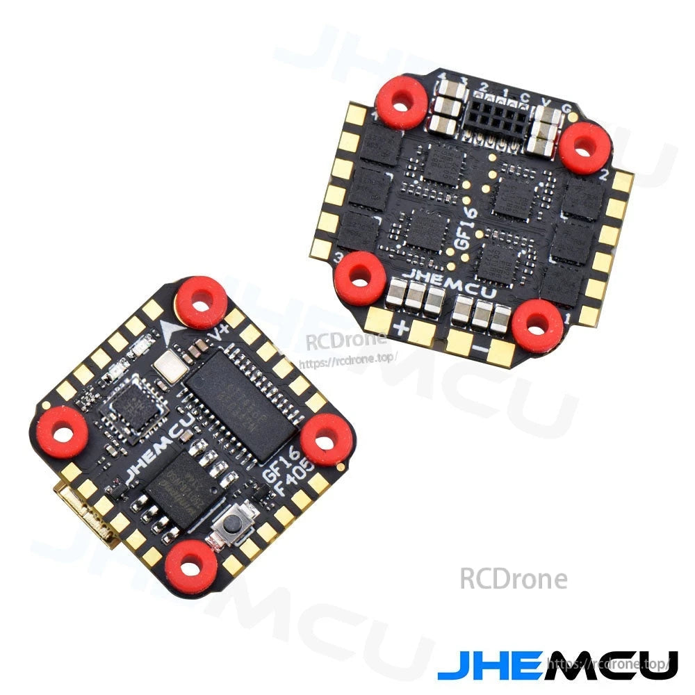
Overview
The JHEMCU GF16-BMI stack combines a GF16 F405 flight controller with a 13A ESC for compact quadcopter builds. The wiring diagram shows support for 2–4S LiPo input, camera power/video connections, and common RC receiver signal types.
Key Features
- GF16 F405 flight controller + 13A ESC stack design
- ESC power input: 2–4S LiPo
- Motor outputs labeled Motor #1 to Motor #4 on the ESC
- Camera connection pads: VIDEO / +5V / GND
- Receiver wiring support shown for: SBUS, IBUS, TBS, DSM
- UART/IO pads are labeled on the flight controller for straightforward soldering
For wiring or configuration help, contact support at https://rcdrone.top/ or email [email protected].
Specifications
| Brand | JHEMCU |
| Stack / FC series shown | GF16 F405 STACK |
| Flight controller marking | GF16 F405 |
| ESC current rating | 13A |
| ESC input | 2–4S LiPo |
| Weight shown (2 boards) | 5.8 g |
Pad Labels / Connections Shown
Flight controller pads (as labeled)
- Top edge: LED, TX6, RX6, +5V, GND
- Left edge: TX3, RX3, SCL, SDA, RX2, TX2, BUZ-, BUZ+
- Right edge: BAT+, GND, +5V, VTX, RX4, TX4
- Bottom edge: +3.3V, GND, SBUS, +4.5V, GND
- Camera: VIDEO, +5V, GND
Receiver wiring examples shown
- SBUS receiver: GND, +4.5V, SBUS, RC
- IBUS receiver: GND, +4.5V, IBUS, RC
- TBS receiver: GND, +4.5V, TX, RX
- DSM receiver: GND, +3.3V, RC
ESC pads shown
- Battery: + / -
- Motors: Motor #1, Motor #2, Motor #3, Motor #4
Wiring Note Shown
- When using an external receiver such as SBUS/IBUS/DSM/TBS, set UART1 to Serial RX in the Ports configuration.
What's Included
- JHEMCU GF16 F405 flight controller (1 pc)
- ESC board (1 pc)
- Power wires (red/black)
- Connector (yellow housing, as shown)
- Electrolytic capacitor
- Mounting hardware: 4 screws and 4 nuts
Details
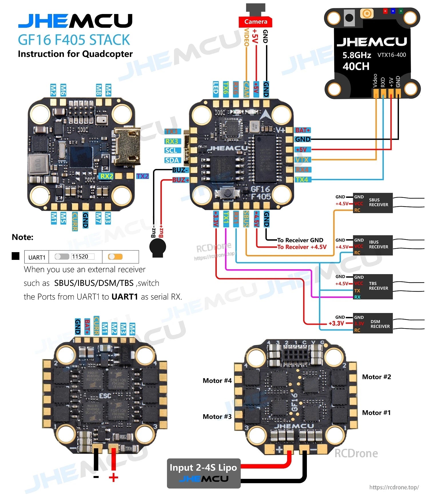
Wire the compact GF16 F405 + 13A ESC stack for 2–4S LiPo input, camera/VTX pads, and common receiver signal types.
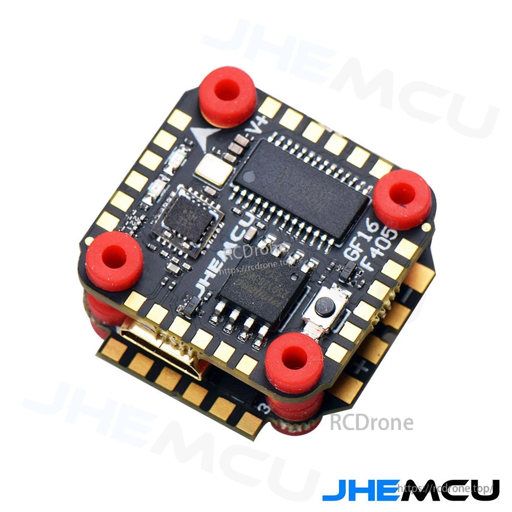
The stacked design keeps a clean footprint for small quad builds while maintaining clearly labeled solder pads.
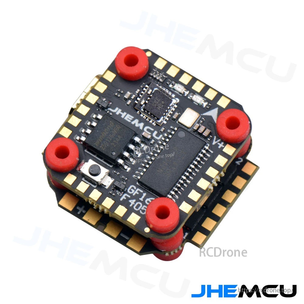
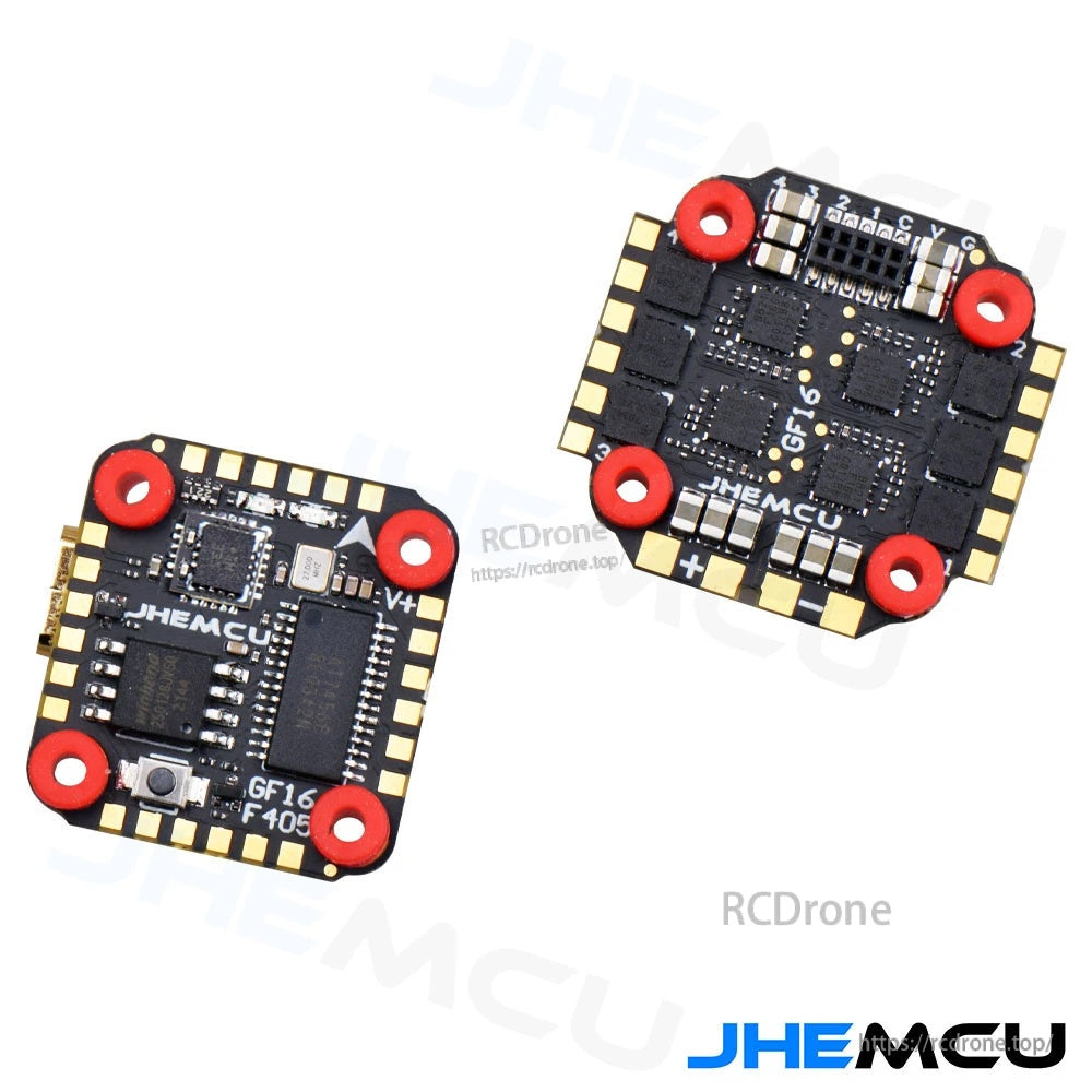
Separate boards make it easy to inspect pad labels and connector placement before final soldering.
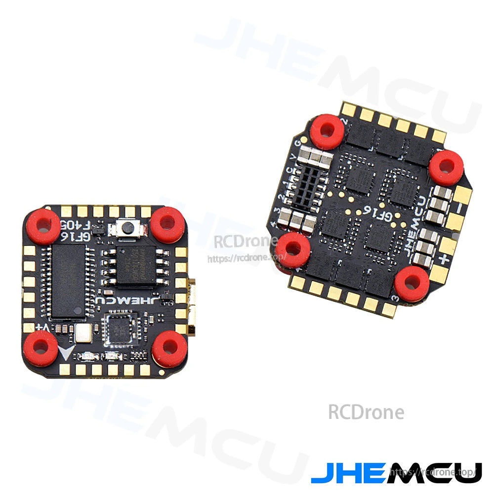
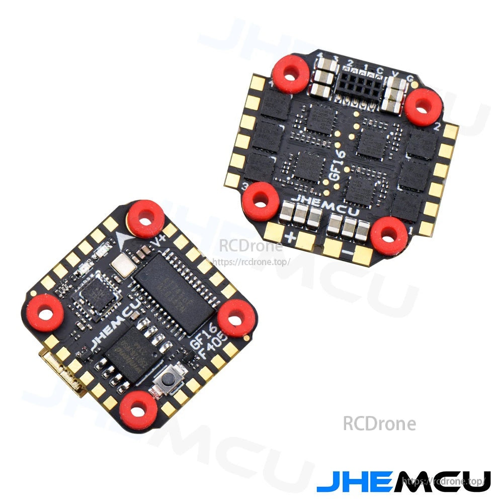
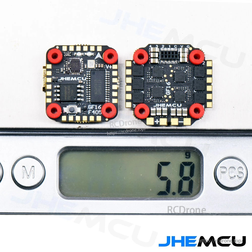
Total weight for the two-board stack is about 5.8 g for lightweight builds.
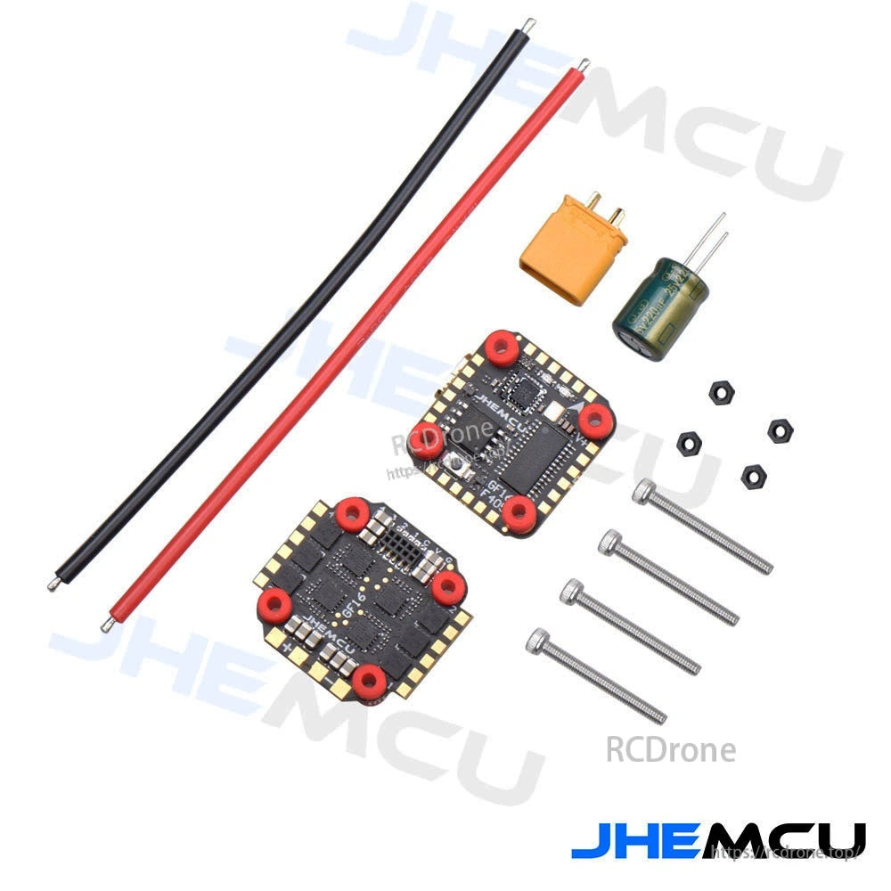
The kit includes the FC, ESC, power leads, connector, capacitor, and mounting hardware to finish the install.