BrotherHobby Returner F435 Betaflight Flight Controller 3S-8S, ICM42688, Type-C, 16M Blackbox
BrotherHobby Returner F435 Betaflight Flight Controller 3S-8S, ICM42688, Type-C, 16M Blackbox
BrotherHobby
Couldn't load pickup availability
Overview
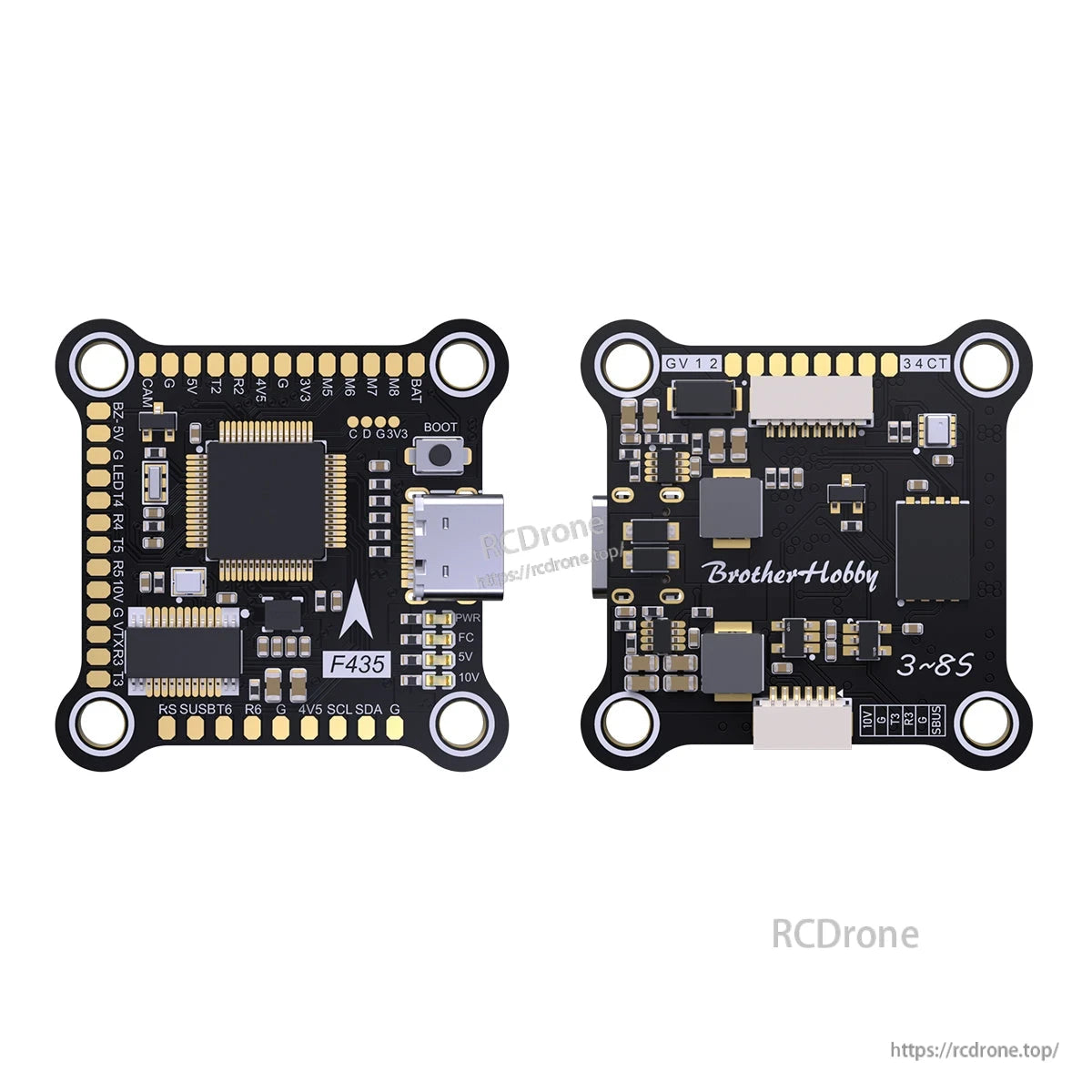
The BrotherHobby Returner F435 is a Betaflight flight controller designed for 3S-8S builds, featuring an AT32F435RGT7 MCU, ICM-42688 IMU, onboard OSD, barometer, and 16M blackbox flash. It uses a TYPE-C USB port and provides dual independent BEC outputs (5V/2A and 10V/2A) for powering common FPV and accessory devices.
Key Features
- CPU: AT32F435RGT7 (Frequency: 288MHZ)
- IMU: ICM-42688 (ICM42688 gyroscope with an 8KHz sampling rate)
- Supports bidirectional DShot digital throttle communication
- 6-layer board design, 1OZ copper thickness
- Dual independent power supply BEC: 10V2A + 5V2A (LC filters added to the 10V power supply for more stable image transmission devices)
- Blackbox support: 16M (flash memory; records and stores more flight logs)
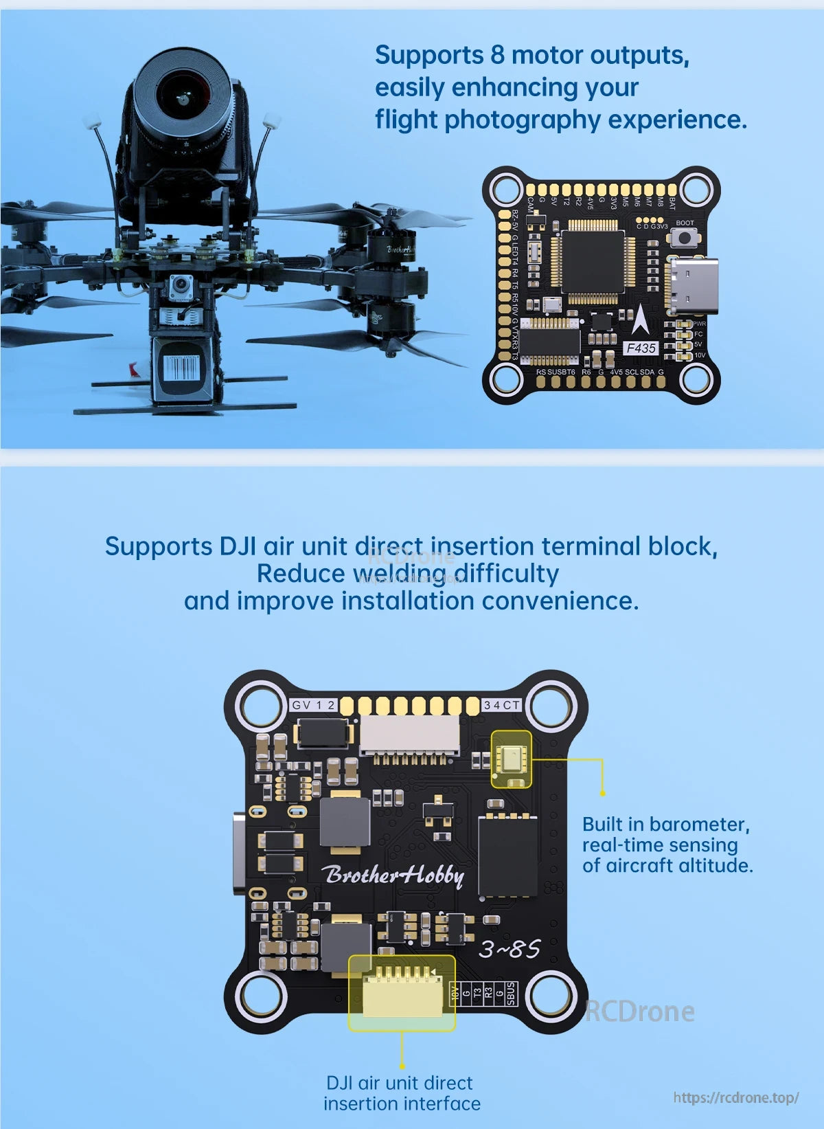
- Supports 8 motor outputs (ESC outputs M1-M8)
- Built-in barometer (real-time sensing of aircraft altitude)
- DJI: Supports direct insertion and welding; supports DJI air unit direct insertion terminal block to reduce welding difficulty and improve installation convenience
- IIC support; supports external LED
- Target firmware: betaflight 4.5.0 BROTHERHOBBYF435
Specifications
| Product | BrotherHobby F435 |
| CPU | AT32F435RGT7 |
| CPU Frequency | 288MHZ |
| Input Power | 3S-8S |
| Dimensions | 38.5*38.5mm (30.5x30.5mm hole diameter 4mm) |
| IMU | ICM-42688 |
| OSD | AT7456E |
| Barometer | SPL06-001 |
| Black box | Support (capacity: 16M) |
| BEC | 5V/2A, 10V/2A |
| DJI | Supports direct insertion and welding |
| IIC | Support |
| UART / Telemetry | UART1, UART2, UART3, UART4, UART5, UART6; UART1 is ESC Telemetry telemetry |
| USB Port | TYPE-C |
| Galvanometer port | Pad CUR |
| ESC outputs | M1-M8 |
| LED | Support external LED |
| Target firmware | betaflight 4.5.0 BROTHERHOBBYF435 |
| Receivers | SBUS, IBUS, DSM2/X, TBS, CRSF |
| Buzzer | Yes |
| RSSI | Yes |
| Weight | 7.82g |
What’s Included
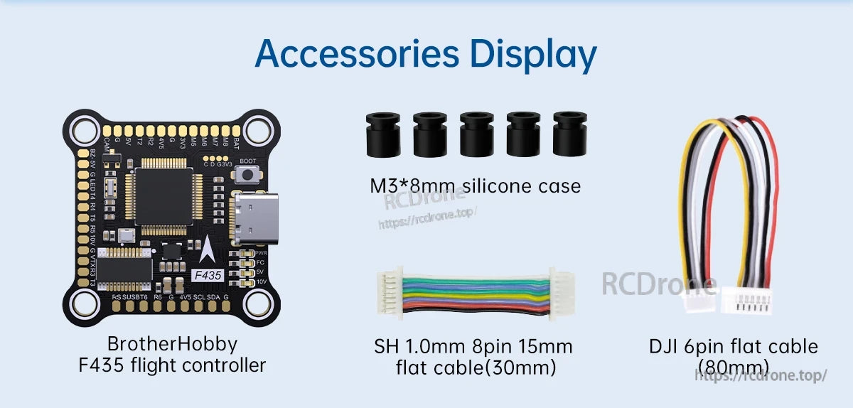
- BrotherHobby F435 flight controller
- M3*8mm silicone case
- SH 1.0mm 8pin 15mm flat cable (30mm)
- DJI 6pin flat cable (80mm)
Applications
- Supports 5-13 inch drone builds
- Multi-motor builds requiring up to 8 motor outputs (M1-M8)
- Compatible power outputs for 5V devices such as analog cameras, analog image transmission, and LED light strips
- Accessory integration via IIC (e.g., GPS wiring shown)
Installation Notes
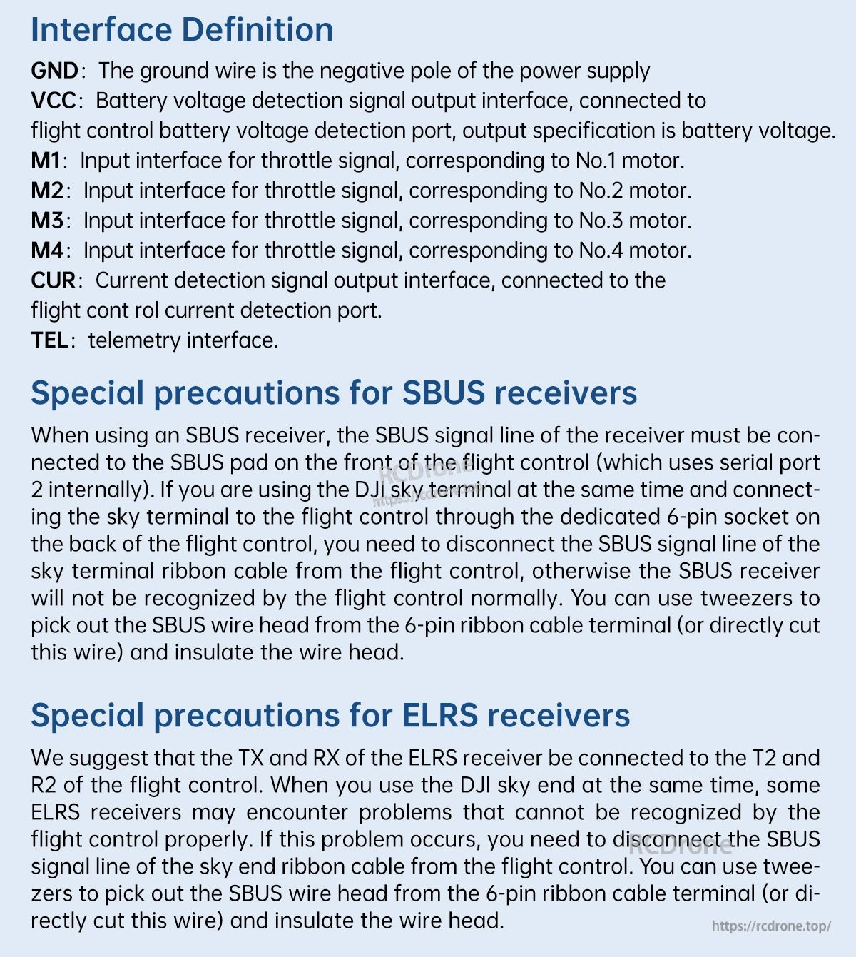
Interface Definition (as labeled)
- GND: The ground wire is the negative pole of the power supply
- VCC: Battery voltage detection signal output interface; connected to the flight control battery voltage detection port; output specification is battery voltage
- M1: Input interface for throttle signal, corresponding to No.1 motor
- M2: Input interface for throttle signal, corresponding to No.2 motor
- M3: Input interface for throttle signal, corresponding to No.3 motor
- M4: Input interface for throttle signal, corresponding to No.4 motor
- CUR: Current detection signal output interface; connected to the flight control current detection port
- TEL: Telemetry interface
Special Precautions for SBUS Receivers
- When using an SBUS receiver, the SBUS signal line of the receiver must be connected to the SBUS pad on the front of the flight control (which uses serial port 2 internally).
- If using the DJI sky terminal at the same time and connecting the sky terminal to the flight control through the dedicated 6-pin socket on the back of the flight control, disconnect the SBUS signal line of the sky terminal ribbon cable from the flight control; otherwise the SBUS receiver will not be recognized normally.
- Tweezers can be used to pick out the SBUS wire head from the 6-pin ribbon cable terminal (or directly cut this wire) and insulate the wire head.
Special Precautions for ELRS Receivers
- Suggested connection: TX and RX of the ELRS receiver to T2 and R2 of the flight control.
- When using the DJI sky end at the same time, some ELRS receivers may not be recognized properly. If this occurs, disconnect the SBUS signal line of the sky end ribbon cable from the flight control.
- Tweezers can be used to pick out the SBUS wire head from the 6-pin ribbon cable terminal (or directly cut this wire) and insulate the wire head.
For wiring questions or compatibility checks before purchase, contact [email protected] or visit https://rcdrone.top/.
Details
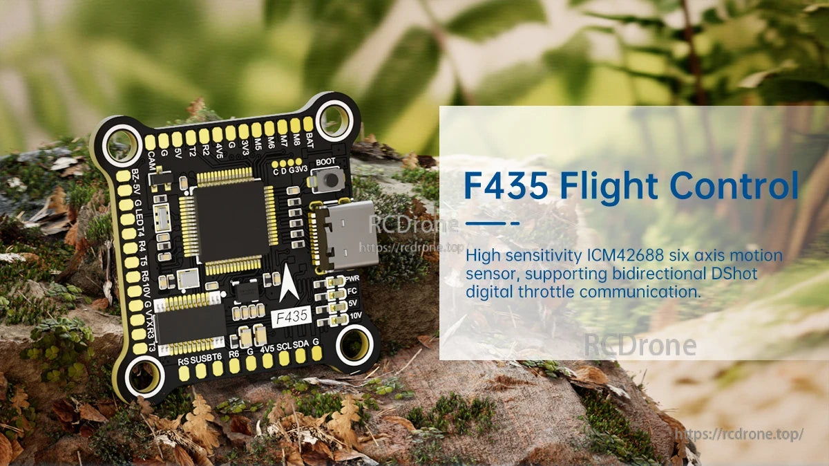
The Returner F435 flight controller uses an ICM42688 6-axis motion sensor and supports bidirectional DShot for digital throttle communication.
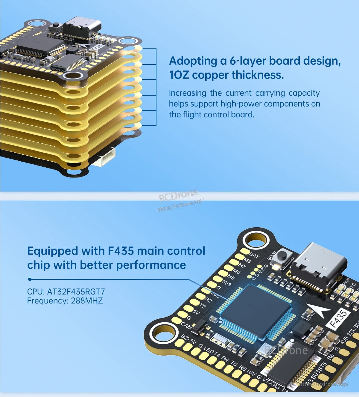
The Returner F435 flight controller uses a 6-layer, 10oz copper board and an AT32F435RGT7 MCU (288MHz) with a USB-C port for setup.
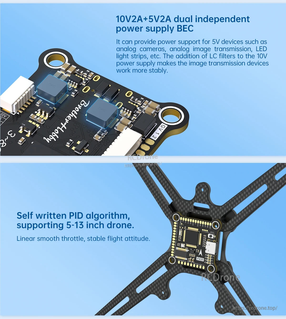
BrotherHobby Returner F435 flight controller provides dual independent 10V/5V BEC outputs and a USB-C port for straightforward wiring on 5–13 inch builds.
The Returner F435 flight controller uses a USB-C connection, supports up to 8 motor outputs, and includes a DJI Air Unit direct insertion interface.
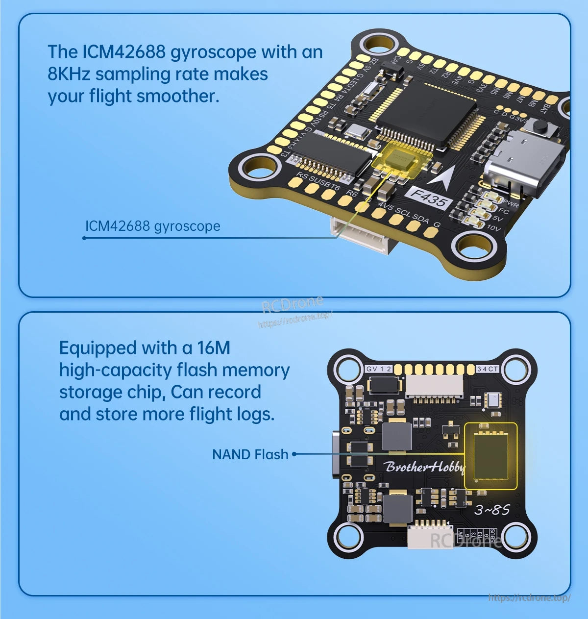
The Returner F435 flight controller pairs an ICM42688 gyro (8 kHz sampling) with 16M onboard flash for storing more flight logs.
BrotherHobby Returner F435 flight controller includes M3×8mm silicone grommets plus an SH 1.0mm 8-pin flat cable and a DJI 6-pin flat cable for clean wiring.
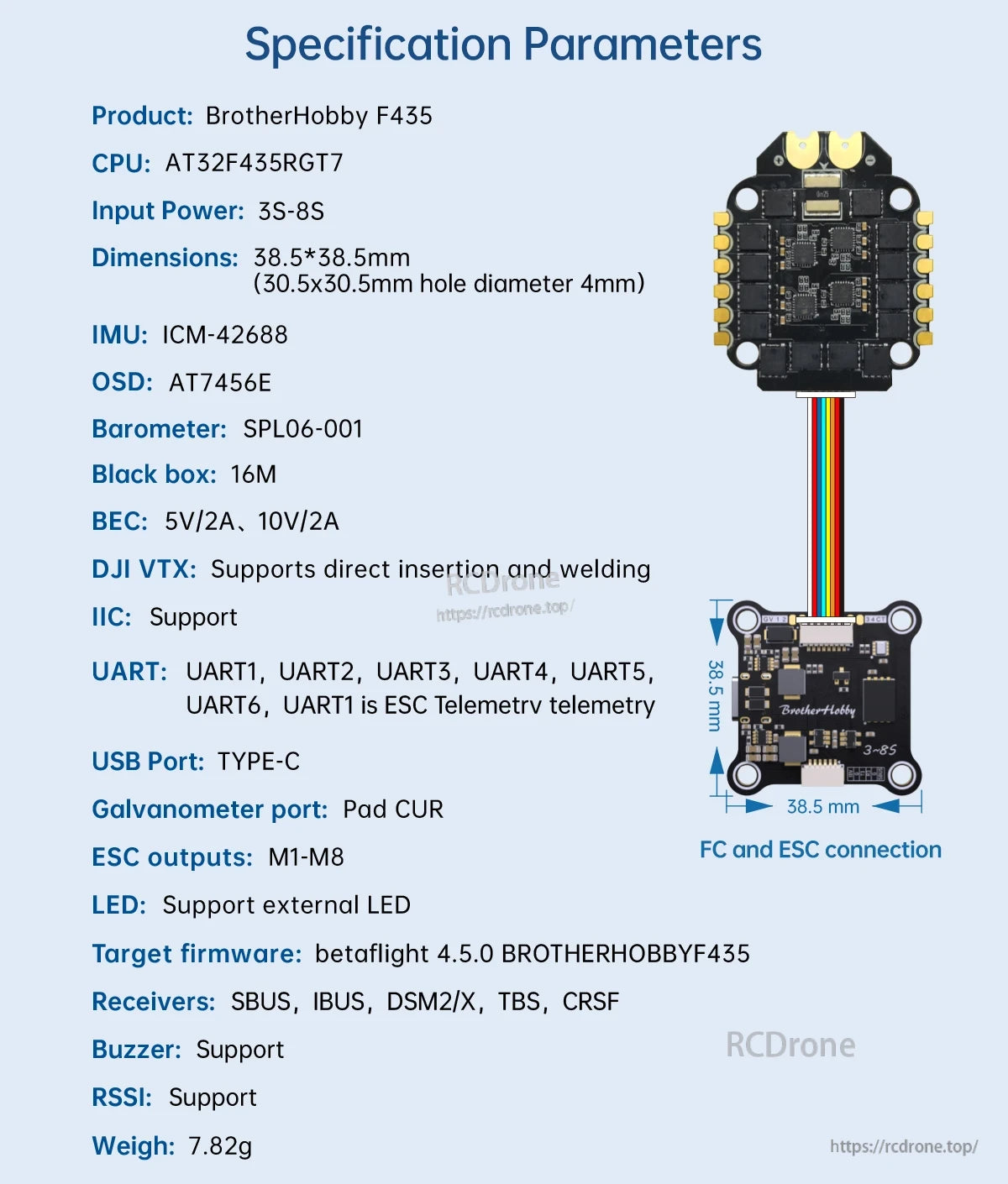
BrotherHobby Returner F435 uses a Type‑C USB port and a ribbon cable connector for a clean FC-to-ESC stack wiring layout.
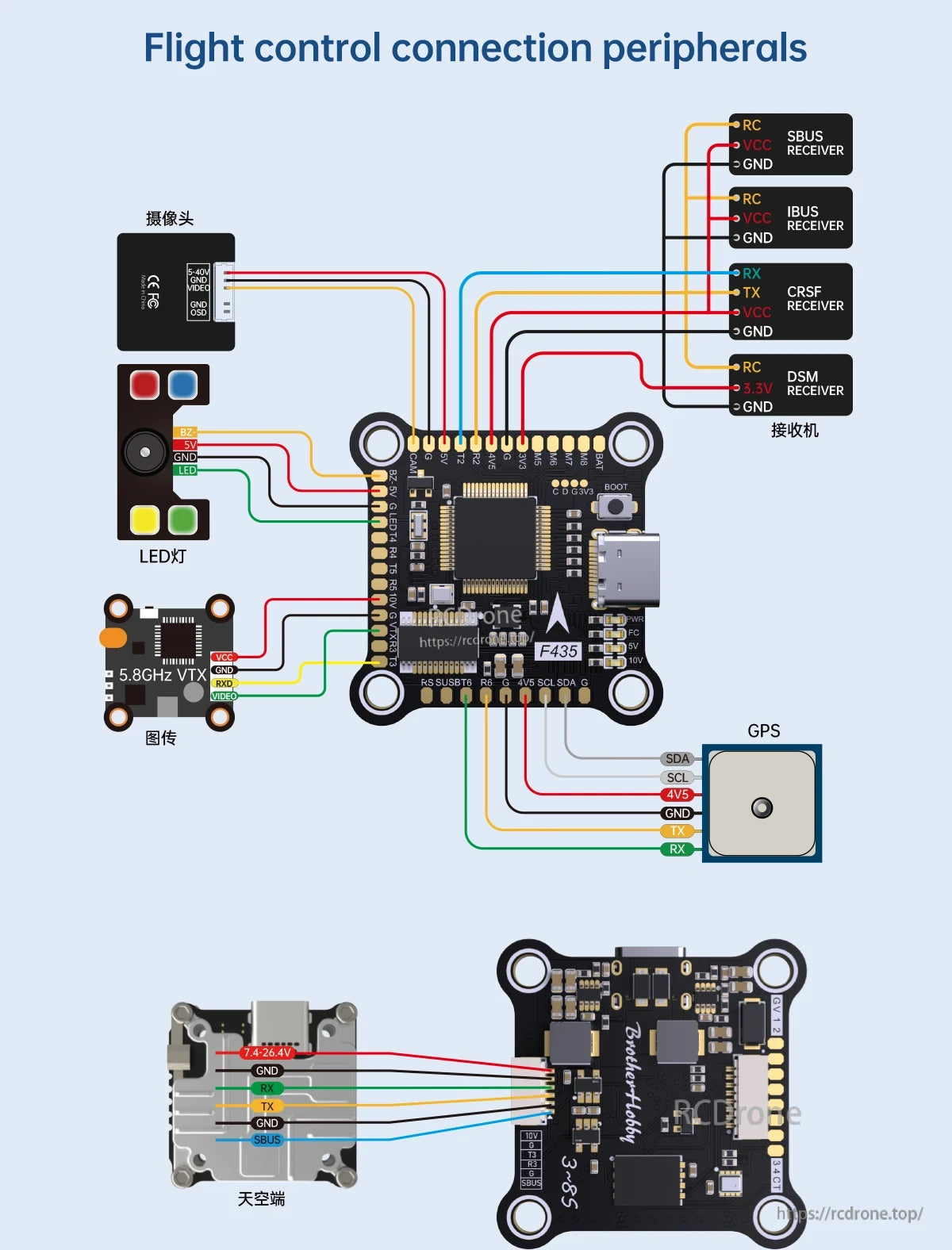
The Returner F435 flight controller provides clearly labeled pads for SBUS/iBUS/CRSF/DSM receivers plus GPS, VTX, camera, and LED wiring.
The Returner F435 wiring guide lists key pads like GND, VCC, M1–M4, CUR, and TEL, plus setup precautions for SBUS and ELRS receivers.
Related Collections