BrotherHobby Avenger 3-8S 4.8-6.2G VTX Video Transmitter 7W, 96CH, IRC Tramp, SMA
BrotherHobby Avenger 3-8S 4.8-6.2G VTX Video Transmitter 7W, 96CH, IRC Tramp, SMA
BrotherHobby
Couldn't load pickup availability
Overview
BrotherHobby Avenger 3-8S 4.8-6.2G VTX 7W is a high-power analog FPV VTX (video transmitter) with 96CH support, IRC Tramp control, and four selectable power levels (PIT/0.6W/3W/7W). It supports NTSC/PAL video formats and uses an SMA antenna connector.
Key Features
- Power adjustable in 4 levels: PIT / 0.6W / 3W / 7W
- 96CH channel support
- Communication protocol: IRC Tramp
- Built-in audio, supports recording; onboard microphone for real-time transmission of aircraft sound to the ground
- Top heat dissipation design with heat dissipation shell and axial fan (designed to improve heat dissipation effect and help keep emission power stable and long-lasting)
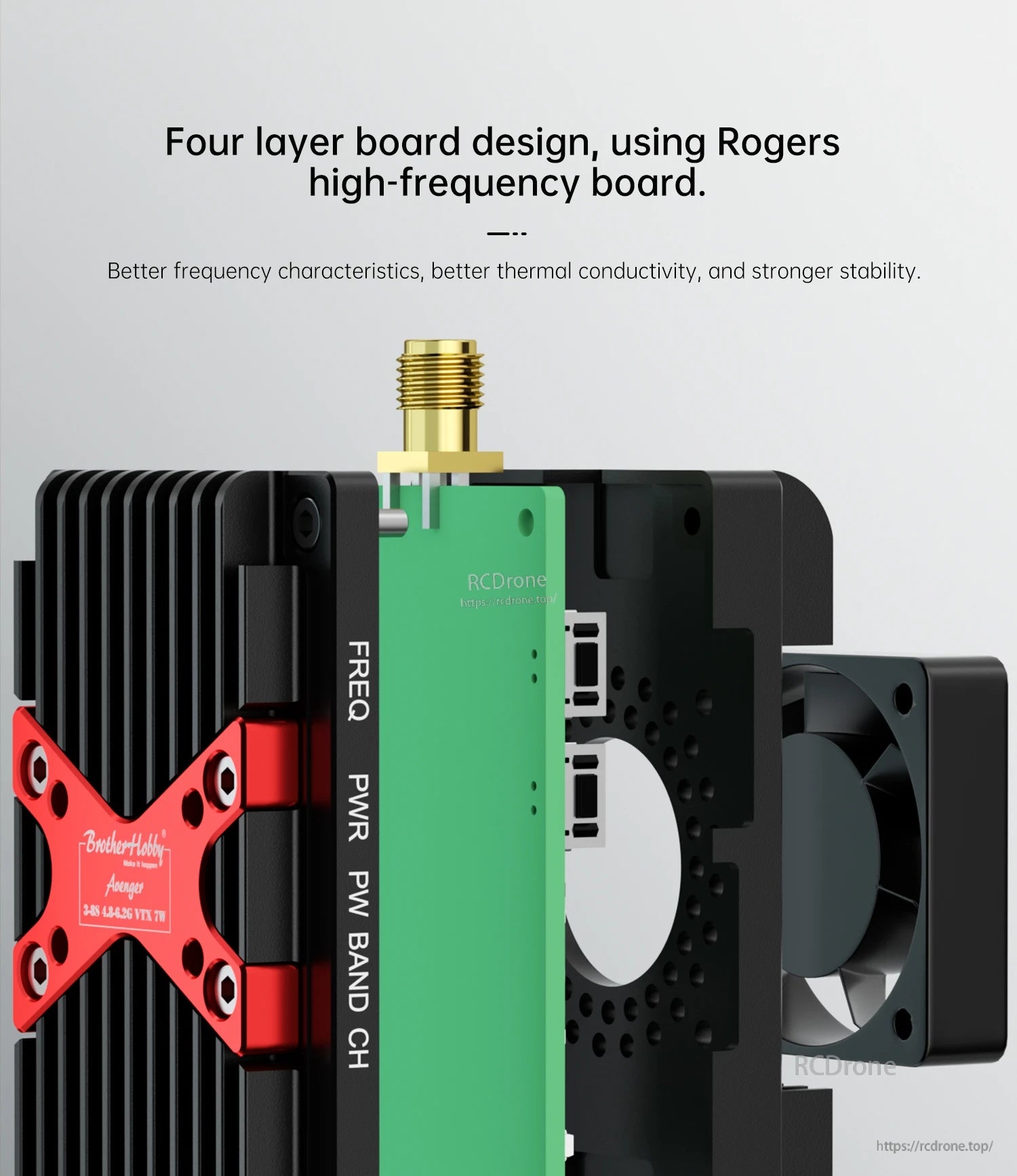
- Four-layer board design using Rogers high-frequency board (better frequency characteristics, better thermal conductivity, stronger stability)
For wiring/compatibility questions, contact [email protected] or visit https://rcdrone.top/.
Specifications
| Product Name | 3-8S 4.8-6.2G VTX 7W |
| Channel | 96CH |
| Power | PIT/0.6W/3W/7W (four adjustable levels) |
| Output voltage | DC 5V |
| Input voltage | DC 12-36V |
| Communication protocol | IRC Tramp |
| Video format | NTSC/PAL |
| Video input impedance | 50 ohm |
| Antenna connector | SMA |
| Circuit board size | 55mm*36.8mm |
| Circuit board weight | 9g (excluding antenna and power cord) |
| External dimensions | Length 57.3mm * Width 38.6mm * Height 22.8mm |
| Weight | 66g |
Interface Definition
- 12-36V: VTX positive input
- GND: VTX negative electrode
- IRC: IRC input
- +5V: 5V power output
- GND: negative electrode
- Video: VIDEO IN
The image transmission power is relatively high; battery direct power supply is recommended. The 5V output is only used for the camera. Do not connect the power input terminal to the 5V output port, otherwise it will damage the video transmission.
Button & LED Operation
- Long press the FREQ button for 3 seconds to enter channel group A-Z adjustment mode. To switch channel groups, long press the FREQ button and short press it to switch between CH1-CH8 cycles.
- Long press the PWR button for 3 seconds to enter power adjustment mode. Short press the PWR button to switch between different power levels.
- Green light indications in power adjustment mode:
- Green light flashes once: 600mW
- Green light flashes twice: 3000mW
- Green light flashes three times: 7000mW
- Press and hold the PWR button again for 3 seconds to enter PIT mode; the green light will not flash.
- Default setting: enters PIT mode when powered on, with channel BOSCAM_A and frequency CH1.
- CH (Channel frequency point): the number of times the red light flashes is the current channel frequency point.
- BAND (Channel group): the number of times the blue light flashes is the current channel group.
- PW (Power): the number of green light flashes corresponds to the current power level.
Frequency Table
| Channel | CH1 | CH2 | CH3 | CH4 | CH5 | CH6 | CH7 | CH8 |
|---|---|---|---|---|---|---|---|---|
| BOSCAM_A | 5645 | 5665 | 5865 | 5705 | 5885 | 5905 | 5925 | 5945 |
| BOSCAM_B | 5740 | 5760 | 5780 | 5800 | 5820 | 5840 | 5860 | 5880 |
| BOSCAM_E | 5725 | 5745 | 5765 | 5785 | 5805 | 5825 | 5845 | 5865 |
| BOSCAM_F | 5733 | 5752 | 5771 | 5790 | 5809 | 5828 | 5847 | 5866 |
| RACEBAND | 5658 | 5695 | 5732 | 5769 | 5806 | 5843 | 5880 | 5917 |
| BOSCAM_L | 5362 | 5399 | 5436 | 5473 | 5510 | 5547 | 5584 | 5621 |
| BOSCAM_J | 4867 | 4884 | 4921 | 4958 | 4995 | 5032 | 5069 | 5099 |
| BOSCAM_X | 4990 | 5020 | 5050 | 5080 | 5110 | 5140 | 5170 | 5200 |
| BOSCAM_U | 5325 | 5348 | 5366 | 5384 | 5402 | 5420 | 5438 | 5456 |
| BOSCAM_I | 5333 | 5373 | 5413 | 5453 | 5493 | 5533 | 5573 | 5613 |
| BOSCAM_K | 5960 | 5980 | 6000 | 6020 | 6040 | 6060 | 6080 | 6100 |
| BOSCAM_Z | 6002 | 6028 | 6054 | 6080 | 6106 | 6132 | 6158 | 6184 |
Frequency-Power Chart (Reference)
The test data is for reference only.
| Frequency (GHz) | Power (dBm) |
|---|---|
| 4.867 | 34 |
| 4.884 | 34.4 |
| 4.990 | 36.2 |
| 5.069 | 37.8 |
| 5.110 | 38 |
| 5.200 | 38.5 |
| 5.333 | 36.9 |
| 5.402 | 38.1 |
| 5.438 | 36.1 |
| 5.547 | 36.8 |
| 5.573 | 36 |
| 5.584 | 36.2 |
| 5.658 | 37.1 |
| 5.705 | 37.7 |
| 5.771 | 37.2 |
| 5.785 | 37.9 |
| 5.800 | 38.2 |
| 5.806 | 37.9 |
| 5.865 | 38 |
| 5.880 | 37.1 |
| 5.945 | 36.6 |
| 5.980 | 36.3 |
| 6.000 | 36.1 |
| 6.060 | 36.5 |
| 6.080 | 37.3 |
| 6.158 | 36.3 |
| 6.184 | 36 |
Precautions for Use
- Before powering on, confirm whether the antenna is installed in place; otherwise it may damage the internal components.
- Supply power strictly according to the prescribed voltage range and confirm that the positive and negative poles are correct before powering on; otherwise the equipment may be burned out.
- It is normal for high temperatures to occur on the surface during video transmission work. Do not touch it directly to avoid burns.
- Pay attention to preventing static electricity during transportation and use.
- Read the instruction manual carefully before use and ensure correct wiring to extend the service life of the module.
- This product is not waterproof or dustproof. Avoid humid environments and stay away from water sources; reduce use in dusty environments to reduce the impact of dust on product performance.
What’s Included
- 3-8S 4.8-6.2G VTX 7W x 1
- 6-pin single head ribbon cable (103.5mm) x 1
- User manual x 1
Details
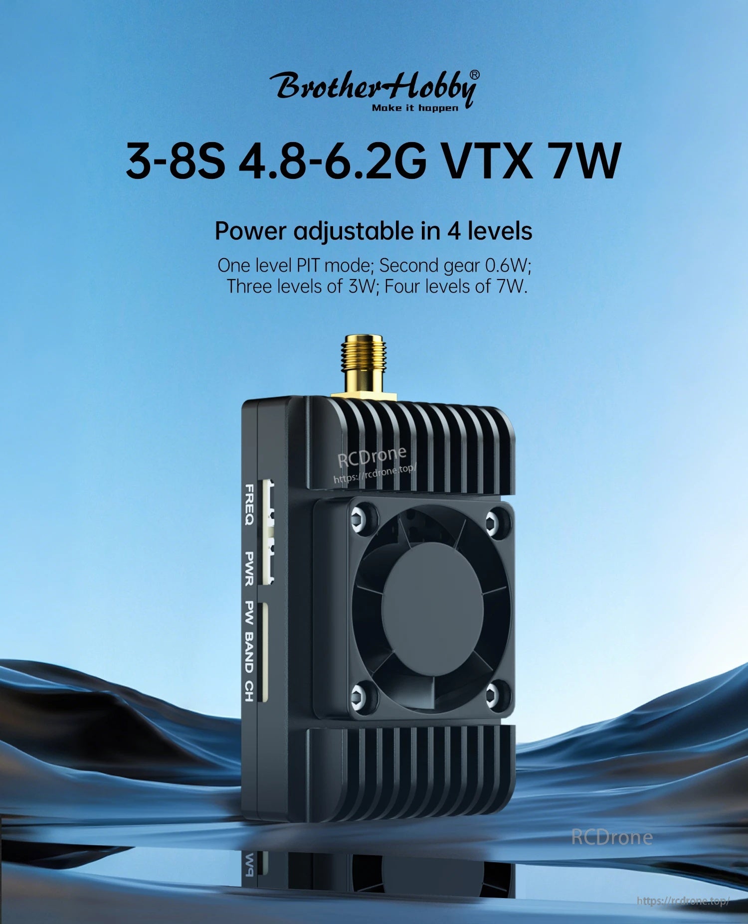
The BrotherHobby Avenger VTX supports 3–8S input, 4.8–6.2GHz output, and six adjustable power levels up to 7W.
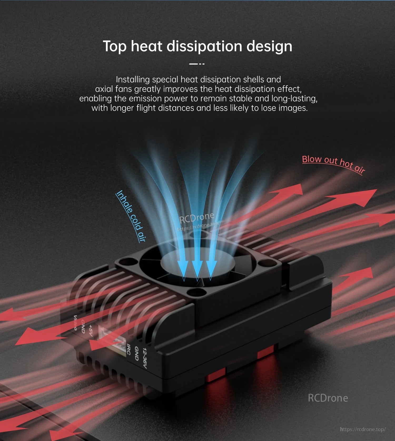
The Avenger VTX uses a top heat-dissipation shell with airflow paths to help keep temperatures more stable during use.
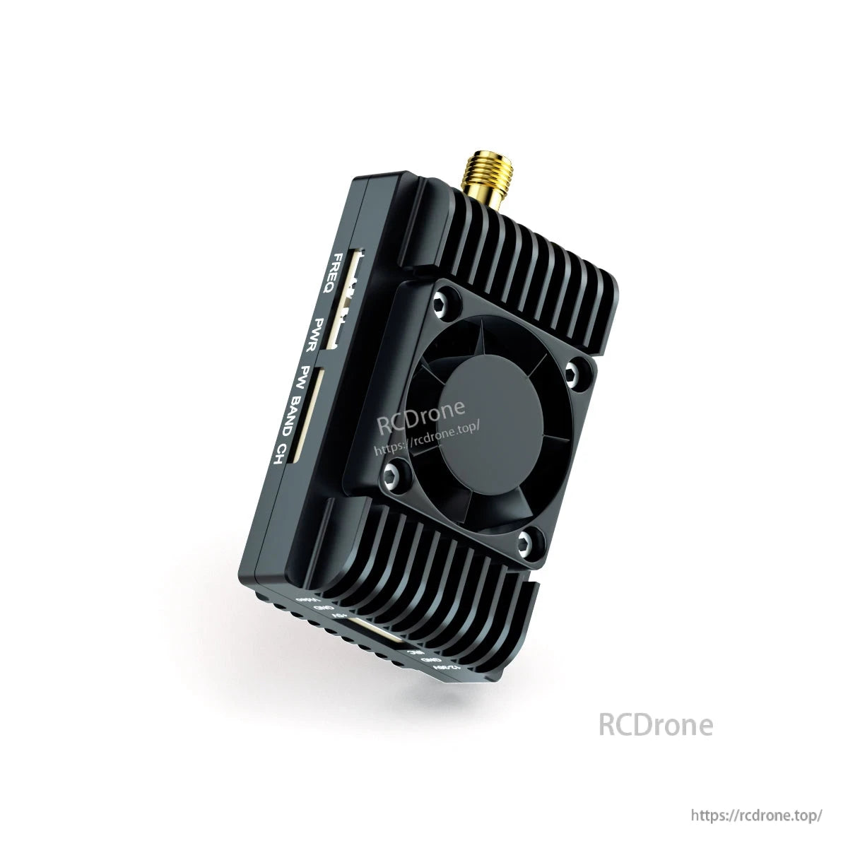
The BrotherHobby Avenger video transmitter uses a finned heatsink and top-mounted fan with an SMA connector for FPV antenna hookup.
The Avenger VTX uses a fan-cooled heatsink design with an SMA antenna connector and side buttons for frequency and power settings.

The Avenger VTX includes an onboard microphone for real-time audio transmission and recording support.

The Avenger 3–8S 4.8–6.2GHz VTX supports 96 channels with PIT/0.6W/3W/7W power levels, IRC Tramp control, and an SMA antenna connector.

The Avenger VTX uses FREQ and PWR buttons with LED flash codes to set band, channel, and power levels.

The 96-channel frequency table lists Boscam and Raceband channel numbers with their corresponding MHz values for quick VTX setup.

The Avenger VTX uses a fan-cooled heatsink design and measures about 66.6 × 38.6 × 22.8 mm for easier mounting.

The BrotherHobby Avenger VTX diagram lays out the SMA antenna connection, button/LED locations, and the 12–36V input, 5V output, IRC, and video-in wiring pins for straightforward installation.

The package includes the Avenger 3–8S 4.8–6.2G VTX, a user manual, and a 6-pin single-head ribbon cable (103.5 mm).
Related Collections