Flywoo GOKU F722 Pro V2 30x30 FC Stack + 55A 4in1 ESC (BL32/AM32) Plug&Play O4/O4 Pro
Flywoo GOKU F722 Pro V2 30x30 FC Stack + 55A 4in1 ESC (BL32/AM32) Plug&Play O4/O4 Pro
FLYWOO
Couldn't load pickup availability
Overview
The Flywoo GOKU F722 PRO V2 30x30 stack combines the GOKU F722 PRO V2 flight controller and the GOKU G55M 55A 4-in-1 ESC. It uses a socket-based, modular plug-in design to simplify wiring and maintenance, while keeping solder pads available for flexible builds. A dedicated plug-and-play connection option is provided for DJI O3 integration, and an analog VTX connection cable is also included.
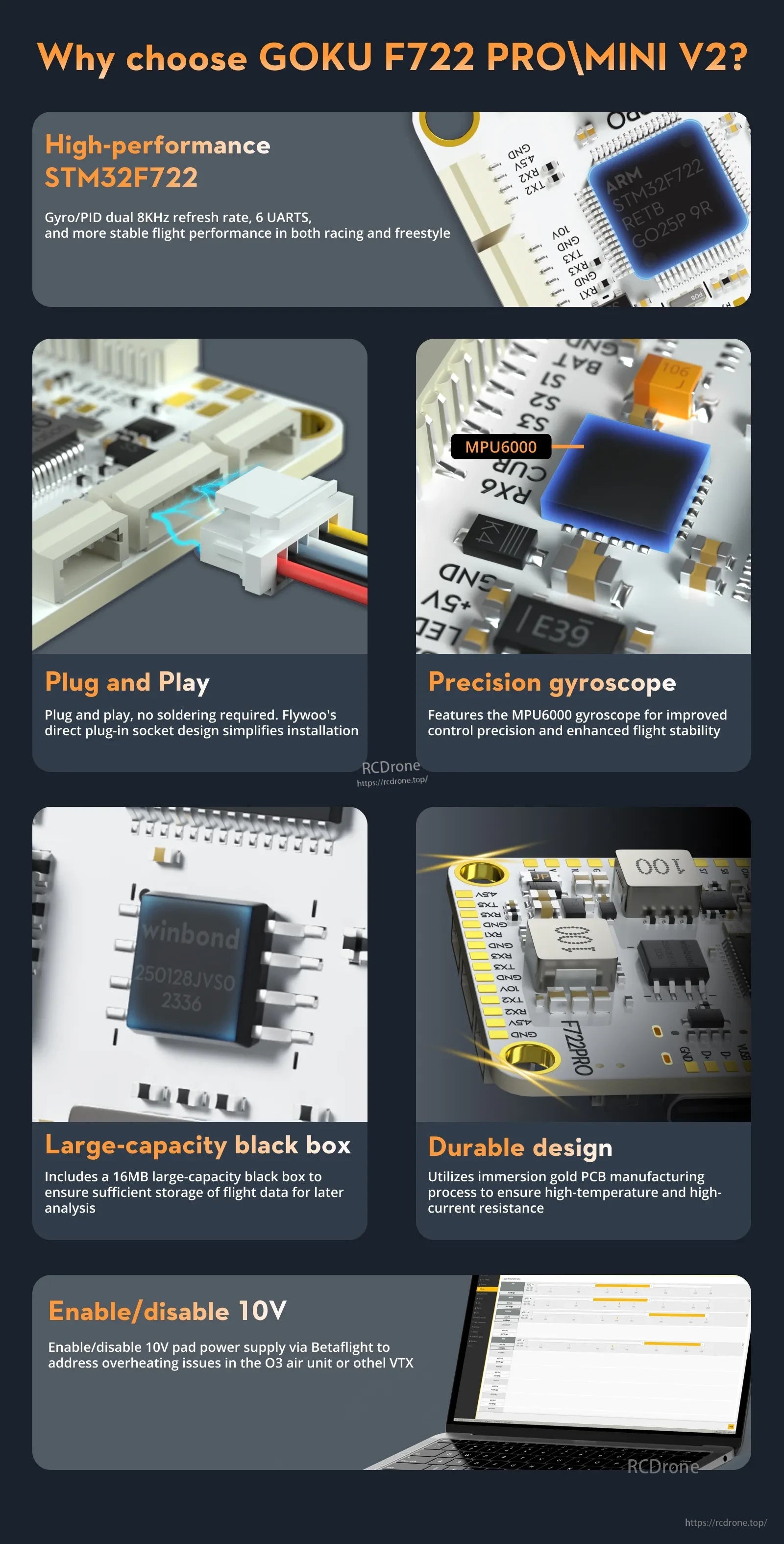
Key Features
- STM32F722 flight controller MCU (up to 216MHz processing speed stated in the provided description)
- 6 UARTs (UARTS: 1/2/3/4/5/6)
- 16MB black box for flight data logging
- Onboard BEC outputs: 10V/3A and 5V/3A
- Supports 8 motor outputs and reserves dual 4-in-1 ESC sockets
- Immersion-gold / gold-plating PCB process noted for high-temperature and high-current resistance
- 10V power can be enabled/disabled via Betaflight (as described in the provided graphics)
Specifications
GOKU F722 PRO V2 Flight Controller
| BF Flight Controller Firmware | FLYWOO F722PRO |
| INAV Firmware | FLYWOO F722PRO |
| MCU | STM32F722 |
| Gyroscope | ICM42688 (spec list). Product graphics also reference MPU6000. |
| OSD | AT7456E |
| Barometer | DPS310 / SPL06 |
| Black Box | 16MB |
| UARTS | 1/2/3/4/5/6 |
| Input Voltage | 7.4V-26V / 2-6S LiPo |
| BEC | 10V3A / 5V3A |
| Flight Controller Size | 37mm x 37mm x 8mm |
| Mounting Holes | M3 30.5 x 30.5mm |
| Weight | 9.9g |
GOKU G55M BL32 / AM32 4-in-1 ESC
| Firmware Support | BL32 / AM32 (depends on version ordered) |
| Signal Protocol | Dshot300, Dshot600, Dshot1200 |
| PWM Frequency | 24k-128k |
| Input Voltage | 3-6S Lipo |
| Continuous Current | 55A |
| Firmware (BL32) | GOKU_F4A32_PRO |
| Firmware (AM32) | AT32DEVF421 |
| Weight | 15g |
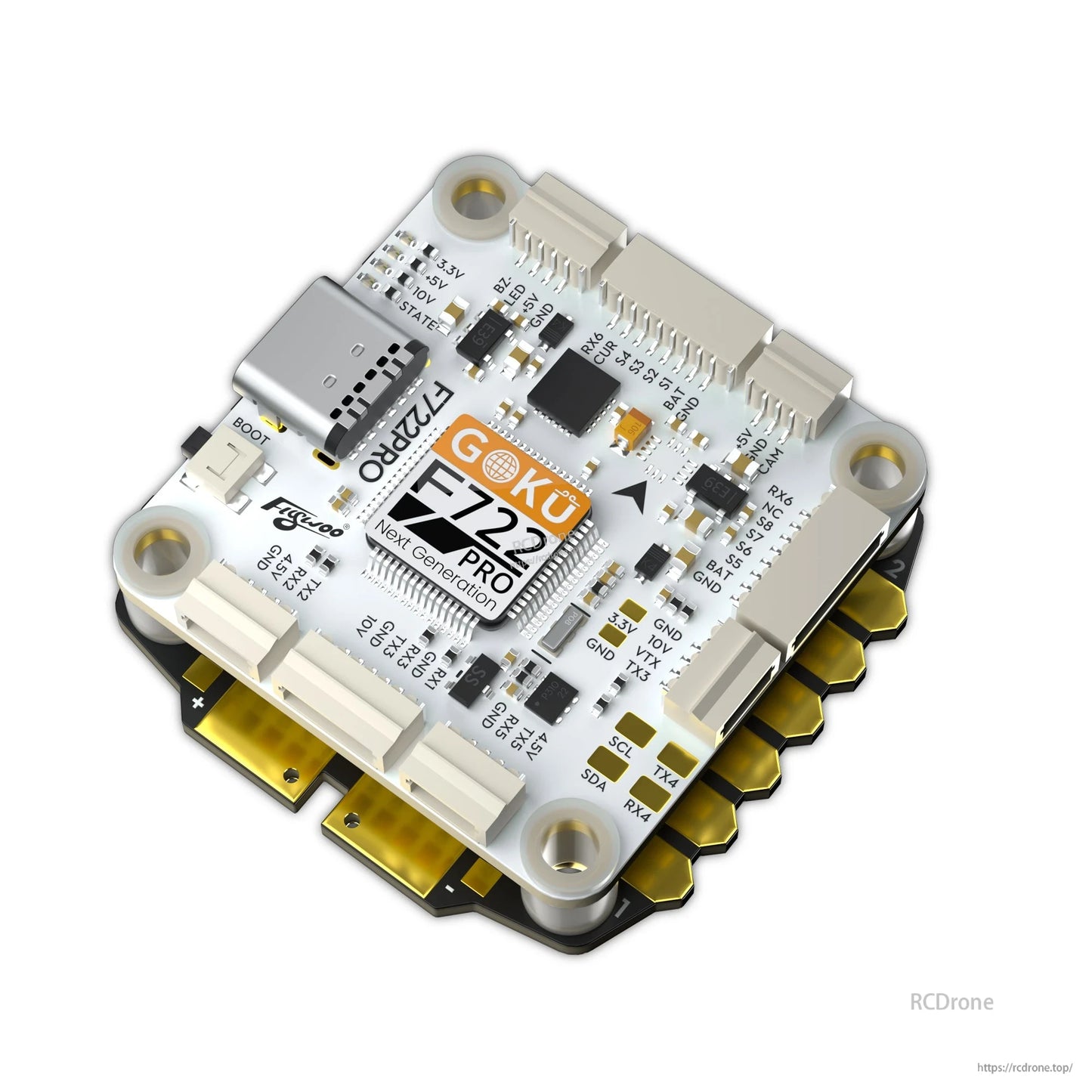
Ports / Pad Labels (from the layout graphics)
- Top: BZ-, LED, +5V, GND
- Top: RX6, CUR, S4, S3, S2, S1, BAT, GND
- Top: +5V, GND, CAM
- Side labels shown: RX6, NC, S8, S7, S6, S5, BAT, GND
- Side labels shown: 3.3V, GND, 10V, VTX, TX3, GND
- I2C / UART labels shown: SCL, SDA, TX4, RX4
- Bottom labels shown: GND, 4.5V, RX2, TX2
- Bottom labels shown: 10V, GND, TX3, RX3
- Bottom labels shown: GND, RX1
- Bottom labels shown: GND, RX5, TX5, 4.5V
- USB pads shown: VUSB, D-, D+, GND
- Indicator labels shown: 3.3V / +5V / +10V / STATE
What’s Included
- 1 x FC&ESC Connection Cable
- 1 x Buzzer Connection Cable
- 1 x GPS Connection Cable
- 1 x DJI O3 Connection Cable
- 1 x Receiver Connection Cable
- 4 x M3 Shock-Absorbing Ball
- 7 x M3 Rubber Ring
- 1 x Analog VTX Connection cable
- 1 x Camera Connection Cable
Notes
- The wiring/compass diagrams indicate I2C (SCL/SDA) connections for a compass/GPS module and describe enabling/disabling 10V via Betaflight modes (USER1).
- For wiring help and compatibility questions, contact [email protected] or visit https://rcdrone.top/.
Details

The Flywoo GOKU F722 Pro Mini V2 flight controller uses a modular plug-in layout with USB-C, 5V/10V pads, MPU6000 gyro, and 16MB black box support.
The GOKU F722 Pro Mini V2 flight controller features an STM32F722 processor, MPU6000 gyro, plug-in sockets, and 16MB blackbox support.
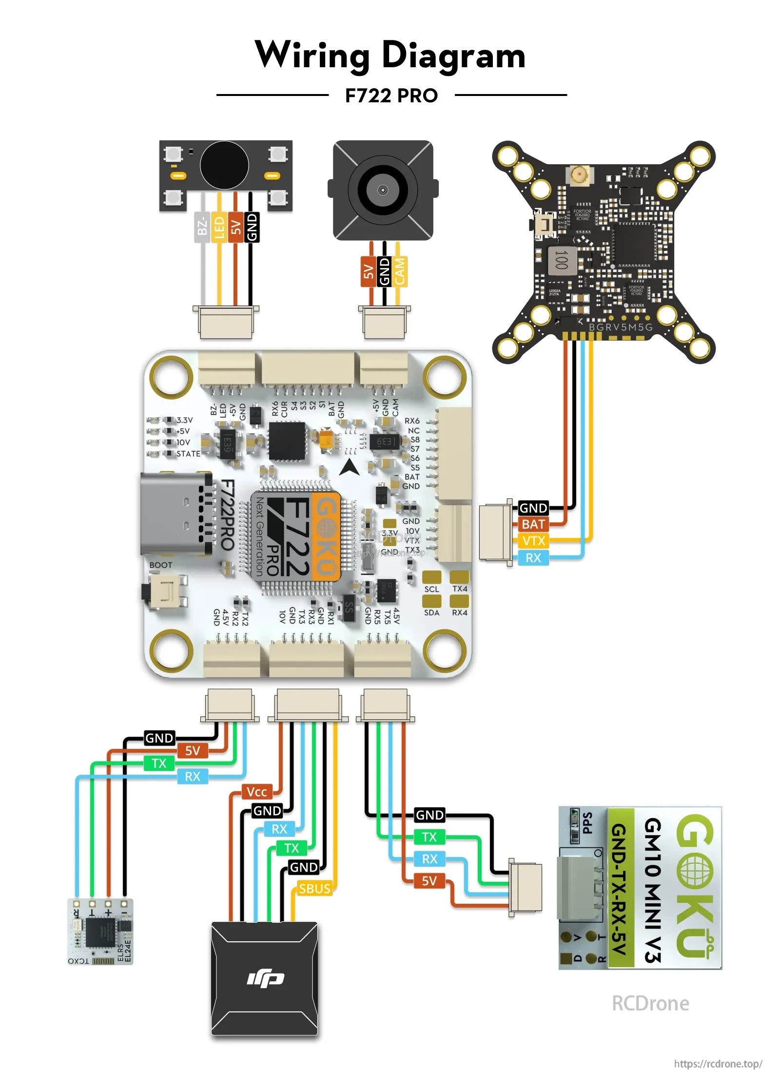
The F722 Pro flight controller wiring diagram labels 5V, GND, BAT, RX/TX, SBUS, and camera/VTX connections for cleaner FPV builds.
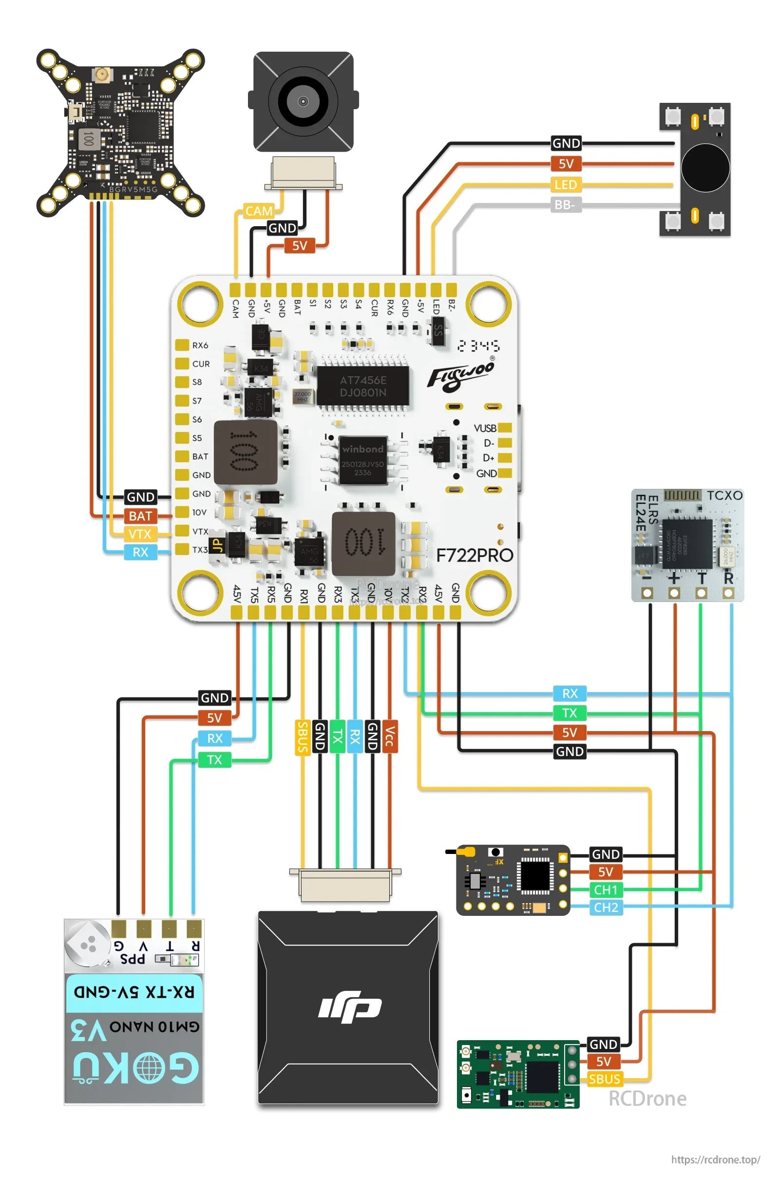
The GOKU F722 Pro V2 flight controller uses clearly labeled pads for camera, VTX, receiver, GPS, and power wiring to simplify a clean build.

Labeled pad layout for the Flywoo GOKU F722 Pro V2 flight controller helps with wiring RX/TX, VTX, camera, and power connections.
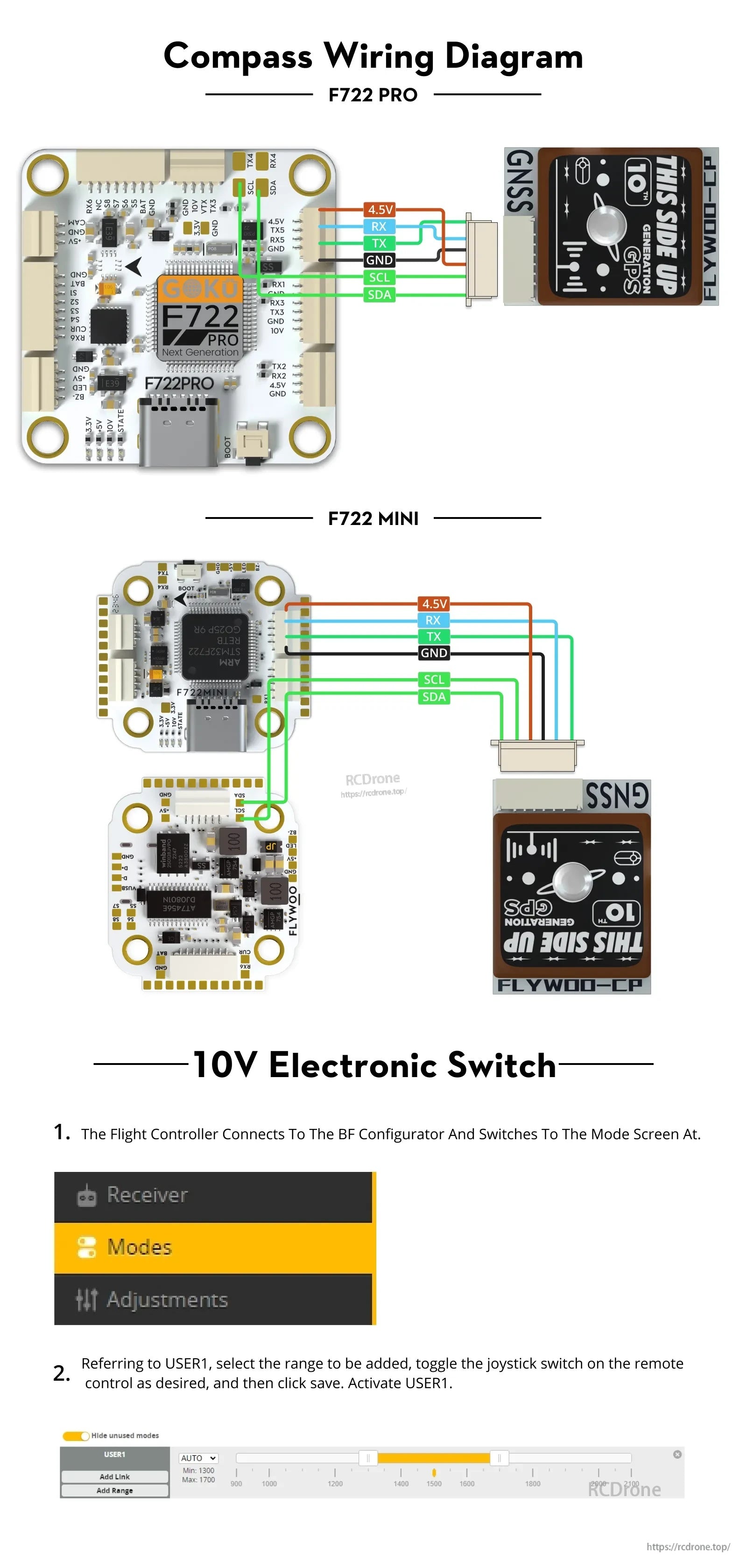
Compass wiring for the GOKU F722 Pro/F722 Mini uses 4.5V, RX/TX, GND, and I2C SCL/SDA pads, with 10V switch control set in Betaflight Modes (USER1).
Related Collections