MAD 9x-12 Drone Arm Set Coaxial Propulsion System: M9C12 100KV, Circular 60A FOC ESC, 30x10 Prop
MAD 9x-12 Drone Arm Set Coaxial Propulsion System: M9C12 100KV, Circular 60A FOC ESC, 30x10 Prop
MAD
Couldn't load pickup availability
Overview
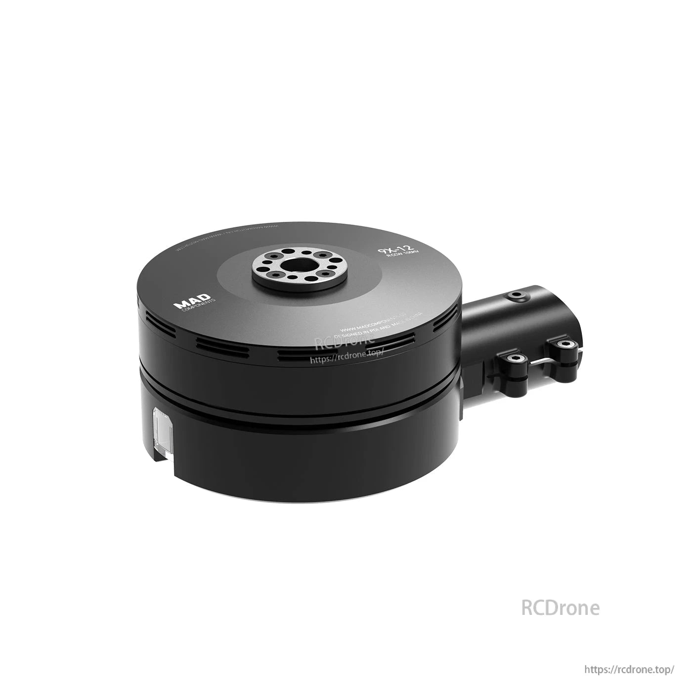
MAD 9x-12 is a drone arm set designed as an upper and lower coaxial structure power system for multirotor aircraft. It is developed for a single axle load of 4.5–6 kg, focusing on force efficiency, safety, and endurance under extreme conditions, and is suitable for aircraft using a 30 mm diameter carbon tube.
Key Features
- Integrated propulsion system with single-arm modular design for convenient installation and a reliable structure.
- Disc motor design (M9C12) with iron-core design and EZO bearings (Japan) and assembly technology intended to reduce axial/radial clearance for stable operation.
- Intelligent sine-wave electric modulation using a Circular 60A FOC intelligent electric regulator with protections including over-voltage, over-current, over-temperature, locked rotor, short circuit, and motor disconnection.
- Red/green LED heading light integrated at the bottom of the power pack.
- Carbon fiber propeller (Fluxer 30x10.0 Pro) with mirror light treatment process and dynamic balance design.
For pre-sales compatibility checks (Ardupilot/DroneCAN integration, wiring length, 30 mm tube fitment) or after-sales support, contact https://rcdrone.top/ or email [email protected].
Specifications
System (9X12 KV100)
| Item | Specification |
|---|---|
| Max thrust | 11952 g / rotor @48v (sea level) |
| Recommended take-off weight | 4400 g–6200 g / rotor @48v (sea level) |
| Recommended voltage | 12S Lipo |
| Operating temperature | -20~60C |
| Unit combo weight | 830 g |
| Extension wire length | 1300 mm / 1300 mm (Input/Signal Wires) |
| Compatible carbon tube | 30 mm |
Propeller
| Item | Specification |
|---|---|
| Diameter / pitch | 30x10.0 inch (762x254 mm) |
| Unit weight | 93 g (p/p) |
Motor
| Item | Specification |
|---|---|
| Stator size | 91x12 mm |
| Unit weight | 483 g |
FOC ESC
| Item | Specification |
|---|---|
| Model name | Circular 60A FOC |
| Max input voltage | 60.9 V |
| Maximum allowable current | 60A (10S) |
| Maximum continuous current | 30A |
| Max throtle signal frequency | 450 Hz |
| Recommended voltage | 12S |
| Compatibility | Ardupilot |
| CAN communication | DroneCan |
Product drawing (dimensions)
| Item | Dimension |
|---|---|
| Overall propeller span | 813.70 |
| Motor/module diameter | Ø98.5 |
| Module length | 63.05 |
| Vertical dimension | 75.25 |
| Vertical dimension | 25.85 |
| Tube clamp height | 39 |
| Compatible tube diameter | Ø30 |
| Mounting pattern | Ø23-M4*4 |
| Mounting pattern | Ø20-M3*4 |
Benchmark (12S)
Setup: MAD 9X12 100KV + FLUXER PRO 30x10 MATT + Circular FOC 60A (6-14S) MAX: 81C
| Throttle [%] | Voltage [V] | Current [A] | Input Power [W] | Output Power [W] | Torque [N×m] | RPM | Thrust [gf] | Efficiency [%] | Efficiency [gf/W] |
|---|---|---|---|---|---|---|---|---|---|
| 30 | 48.76 | 2.38 | 116.0 | 85.8 | 0.576 | 1422 | 1722 | 74.0 | 14.8 |
| 35 | 48.88 | 3.69 | 180.4 | 138.4 | 0.793 | 1667 | 2372 | 76.7 | 13.1 |
| 40 | 48.52 | 5.42 | 263.0 | 209.8 | 1.058 | 1894 | 3155 | 79.8 | 12.0 |
| 45 | 48.30 | 7.22 | 348.7 | 284.5 | 1.288 | 2109 | 3813 | 81.6 | 10.9 |
| 50 | 48.14 | 9.30 | 447.7 | 369.5 | 1.524 | 2318 | 4483 | 82.6 | 10.0 |
| 55 | 48.04 | 11.77 | 565.4 | 475.9 | 1.807 | 2515 | 5251 | 84.2 | 9.3 |
| 60 | 47.95 | 15.13 | 725.5 | 617.3 | 2.185 | 2698 | 6228 | 85.1 | 8.6 |
| 65 | 47.84 | 18.63 | 891.3 | 756.0 | 2.512 | 2874 | 7346 | 84.8 | 8.2 |
| 70 | 47.76 | 21.48 | 1025.9 | 870.8 | 2.731 | 3045 | 7960 | 84.9 | 7.8 |
| 75 | 47.59 | 26.83 | 1276.8 | 1077.4 | 3.207 | 3208 | 9223 | 84.4 | 7.2 |
| 80 | 47.46 | 31.41 | 1490.7 | 1243.8 | 3.534 | 3361 | 10070 | 83.4 | 6.8 |
| 85 | 47.31 | 36.14 | 1709.8 | 1413.6 | 3.847 | 3509 | 10849 | 82.7 | 6.3 |
| 90 | 47.18 | 40.94 | 1931.5 | 1582.0 | 4.139 | 3650 | 11545 | 81.9 | 6.0 |
| 95 | 47.12 | 42.80 | 2016.7 | 1640.3 | 4.230 | 3703 | 11742 | 81.3 | 5.8 |
| 100 | 47.10 | 42.82 | 2016.8 | 1637.7 | 4.221 | 3705 | 11952 | 81.2 | 5.9 |
Use the powertrain correctly according to the performance parameters above. It is recommended to fly at the recommended takeoff weight for best performance. Do not fly overweight. If the takeoff weight exceeds 1.2 times the maximum recommended value, performance and safety will be seriously affected.
Troubleshooting (LED Indicator/Sound)
| LED Indicator/Sound | Cause | Solution |
|---|---|---|
| The motor does not turn after the aircraft is unlocked, but only after the throttle is raised. | Flight control or remote control output unlocked idle throttle value less than 1100us. | Set the idle throttle value of the flight control or remote control to be greater than 1100us. 1160us~1180us is recommended. |
| When the plane is powered on, connect the remote control and the motor turns. | The remote control is set to lock the throttle over 1100us, or close to 1100us. | The remote control needs to set the lock throttle less than or equal to 1050us. |
| When the power-on self-test fails, the motor “beeps” every 1.5 seconds, and the indicator light flashes yellow briefly. | The throttle PWM signal is missing or the identification throttle PWM range is incorrect. | Ensure that the throttle signal cable is properly connected, and check whether the signal cable is damaged. |
| When the power-on self-test fails, the motor “beeps” every 0.5 seconds, and the indicator light flashes yellow briefly. | Detects high throttle when get power and enters protected state. | Make sure that the electric self-test passes before lifting the throttle. |
| The motor does not sound. The indicator light flashes yellow 4 times every 1.5 seconds: “short - short - short - long”. | If the power-on self-test fails, the motor line loop may be disconnected. | Open the ESC cover and check whether the three motor wires are well welded. |
| The motor does not sound. The indicator light flashes yellow 4 times every 1.5 seconds: “long - short - long - short”. | The power-on self-test fails, and the power supply voltage is abnormal. | Check whether the battery voltage is normal. Check whether the power cable is properly connected. |
| The motor does not sound. The indicator light flashes yellow 4 times every 1.5 seconds: other flashing methods. | The power-on self-test fails, and the electrical hardware is abnormal. | Record the LED flashing mode video and contact customer service for assistance. Replace the ESC and test again if required. |
| The power-on self-test is normal, the motor does not turn after unlocking, and the indicator light is yellow for 0.5 seconds - the motor does not sound when the indicator light is off for 0.5 seconds. | Motor startup failure, blocking protection occurred during startup. | Power on and off again and restart the power supply. If it reappears, check whether the motor is damaged. |
| The power-on self-test is normal, the motor does not turn during operation, indicator light: 0.5 seconds yellow light - 0.5 seconds off, the motor does not sound. | The motor is blocked and entered the protection state. | Check whether the machine is blocked, and check whether the motor is smooth by hand. |
| The power-on self-test is normal, the motor does not start or stops midway, indicator light: 1 second yellow light - 1 second off, the motor does not sound. | Short circuit or overcurrent protection occurs, and the device enters the protection state. | Disassemble the electric adjusting cover and check whether the motor line is damaged and whether the copper terminal of the motor line is loose. |
| The indicator light flashes alternately red and green during operation. | The PWM throttle signal is missing. | Land safely and check whether the PWM signal line is well connected and whether the signal line is damaged. |
| The indicator light flashes yellow every 0.2 seconds during operation. | The motor controller detects high temperature. | After the aircraft lands and stops, check whether the temperature of the ESC shell is too high. If the temperature is high, check whether the screws of the wiring position of the ESC are loose. |
Indicator Lights and Audible Alerts for Motor Controller - Rapid Troubleshooting
When in use, rely on the status indicator lights and audible alerts to assess whether the product is functioning properly. If any abnormalities occur, troubleshoot the issues.
Fault During Self-Check
| Fault Symptoms | Possible Causes | Solution |
|---|---|---|
| Power-on self-test failure, the motor emits a “beep” sound every 1.5 seconds, accompanied by a brief yellow flashing indicator light. | Loss or misidentification of throttle PWM signal. Throttle PWM range is incorrect. | Ensure the throttle signal wire is well-connected. Check for any damage to the signal wire. |
| Power-on self-test failure, the motor emits a “beep” sound every 0.5 seconds, accompanied by a brief yellow flashing indicator light. | High throttle detected during power-on, entering protection mode. | Ensure that the motor controller has passed the self-check before increasing the throttle. |
| Power-on self-test failure, the motor is silent, and the indicator light flashes a sequence of four short intervals every 1.5 seconds: “short-short-short-long” in yellow. | Power-on self-test failure, the motor circuit may be disconnected. | Open the motor controller cover and check if the three motor wires are securely locked. |
| Power-on self-test failure, the motor is silent, and the indicator light flashes a sequence of four short intervals every 1.5 seconds: “short intervals every 1.5 seconds” in yellow. | Power-on self-test failure, abnormal supply voltage. | Check if the battery voltage is normal; inspect the power supply line for proper connection. |
| Power-on self-test failure, the motor is silent, and the indicator light flashes a sequence of four short intervals every 1.5 seconds with a yellow light: other flashing patterns. | Power-on self-test failure, abnormality detected in motor controller hardware. | Record the LED flashing pattern on video. Contact customer service for a replacement motor controller and conduct further testing. |
Fault During Operation
| Fault Symptoms | Possible Causes | Solution |
|---|---|---|
| The motors do not spin after the aircraft is unlocked; they start spinning only after increasing the throttle. | The flight controller or remote controller outputs unlocked idle; throttle value is less than 1100 microseconds. | Set the flight controller or remote controller to output idle with a throttle value greater than 1100 microseconds; recommended range 1160uS to 1180uS. |
| After powering on the aircraft and connecting the remote controller, the motors start spinning. | The remote controller is set to lock the throttle at a value above 1100 microseconds or close to 1100 microseconds. | The remote controller needs to be set to lock the throttle at a value less than or equal to 1050 microseconds. |
| Power-on self-test is normal, but the motors do not spin after unlocking. Indicator light: 0.5 seconds of yellow light followed by 0.5 seconds off, and the motors do not produce any sound. | The motor startup failed, encountering stall protection during the startup process. | Power cycle (turn power on and off). If the issue persists, check whether the motor is damaged. |
| Power-on self-test is normal, but the motors do not spin after unlocking. Indicator light: 0.5 seconds of yellow light followed by 0.5 seconds off, and the motors do not produce any sound. | The motor controller detects motor stall and enters protection mode. | Check if the motor is stalled due to a crash and inspect whether the motor rotation is smooth. |
| Power-on self-test is normal, but the motors do not spin after unlocking. Indicator light: 1 second of yellow light followed by 1 second off, and the motors do not produce any sound. | Short circuit or overcurrent protection triggered, entering protection mode. | Open the motor controller cover and inspect whether there is any damage to the motor wires and if the copper connections on the motor wires are loose. |
| During operation, the indicator light alternately flashes red and green. | The motor controller detects a loss of PWM throttle signal. | Land safely, check if the PWM signal line is well-connected, and inspect for any damage to the signal line. |
| During operation, the indicator light rapidly flashes yellow every 0.2 seconds. | The motor controller detects high temperature. | After landing and stopping the aircraft, check if the motor controller’s casing is too hot. If the temperature is high, inspect whether the wire terminal screws are loose. |
| Power-on self-test failure, the motor is silent, and the indicator light flashes a sequence of four short intervals every 1.5 seconds: “short”-“long”-“short”-“short” in yellow. | Power-on self-test failure, abnormal voltage on the motor wires. | Check for any short circuits between the motor wires and the main bus in the motor controller. Inspect whether the motor wires are damaged and whether there is a short circuit with the casing. |
Details
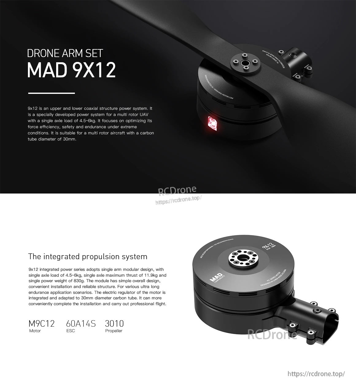
The MAD 9x12 drone arm set uses an integrated propulsion module with a 30mm carbon-tube clamp and labeled M9C12 motor and 60A 14S ESC layout.
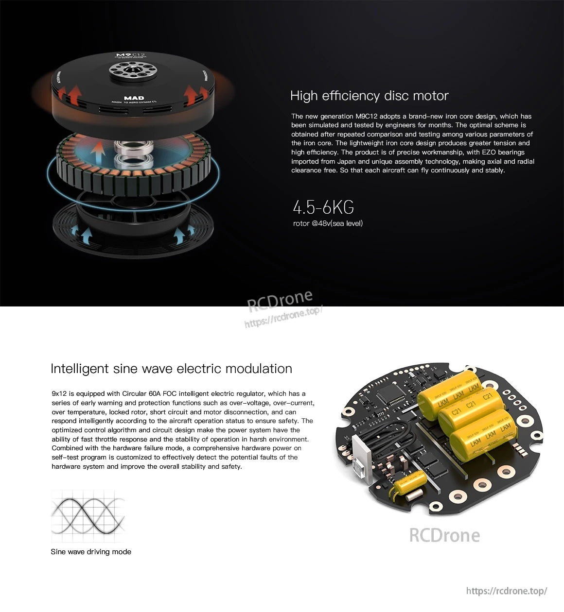
The M9C12 disc motor pairs with a circular 60A FOC regulator using sine-wave driving mode for smoother power delivery.
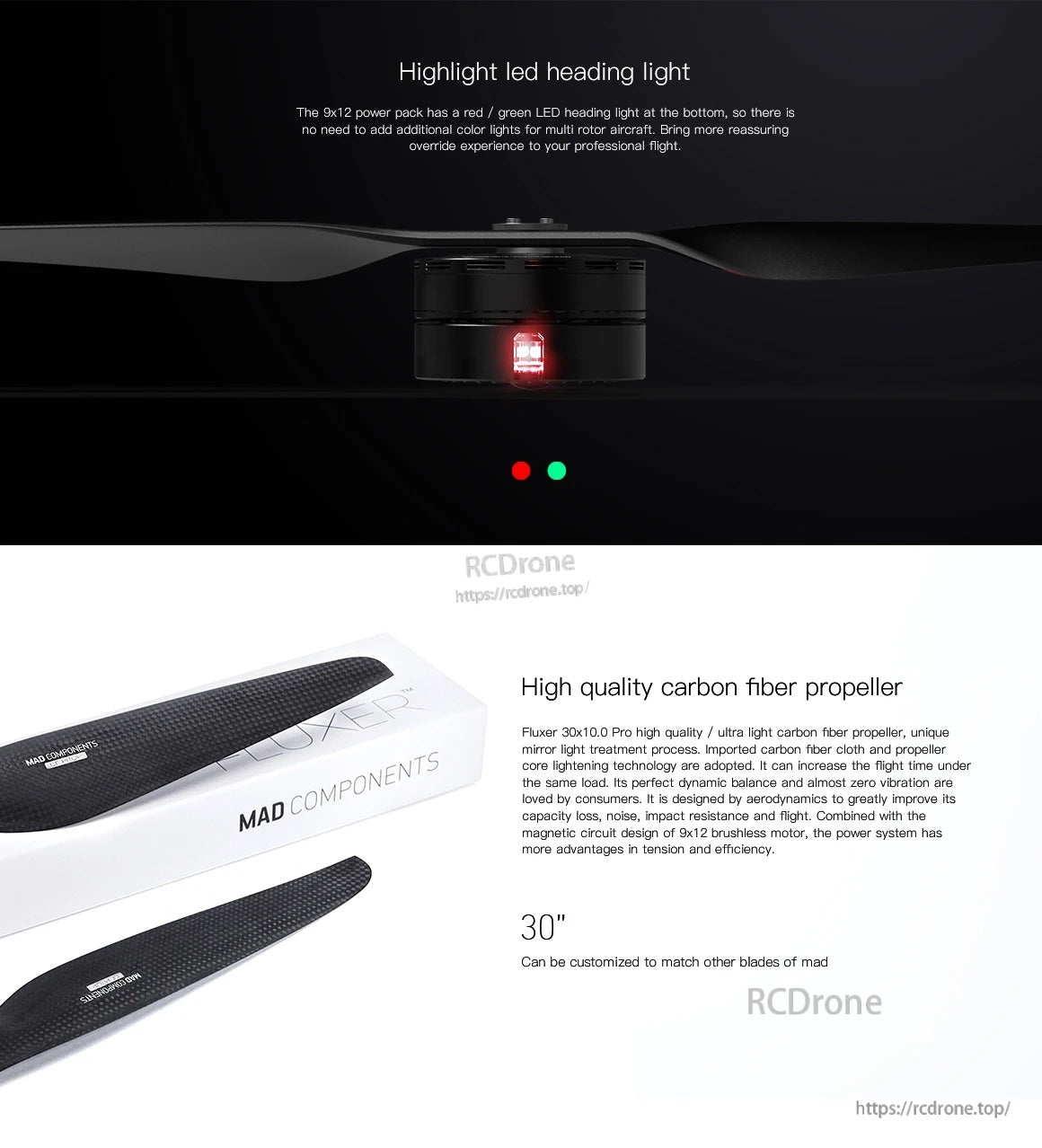
The MAD setup features a carbon fiber propeller and a built-in red/green LED heading light for clearer orientation.
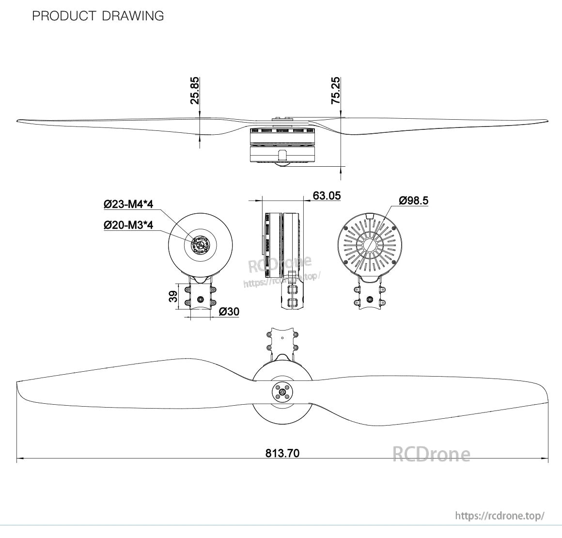
The propeller drawing lists an 813.70 mm overall span and shows the hub mounting hole patterns (Ø23 M4×4 and Ø20 M3×4) for fit checks.
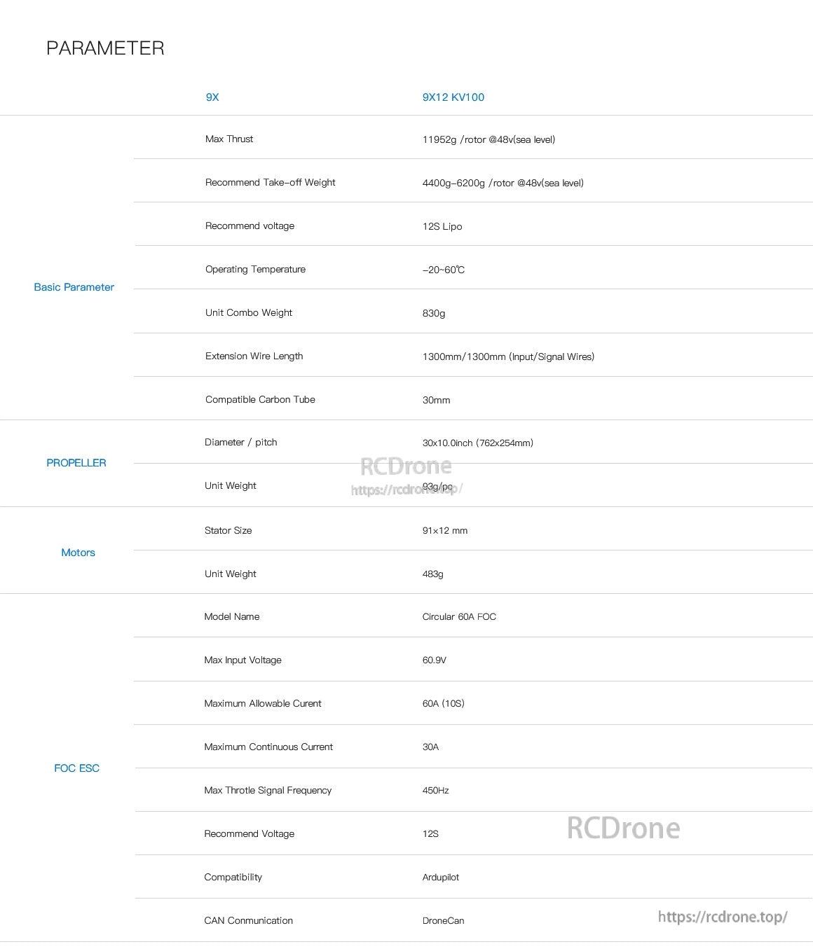
The 9X12 KV100 parameter sheet lists 12S LiPo support, 11,952g max thrust per rotor at 48V (sea level), and 30mm carbon tube compatibility.
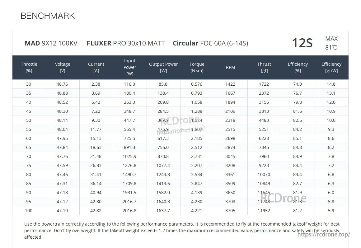
MAD 9x12 100KV 12S benchmark data lists throttle steps with voltage, current, RPM, thrust, and efficiency, with a noted max temperature of 81°C.

The ESC troubleshooting guide matches LED indicator and beep patterns to common causes and wiring checks for quicker diagnosis.
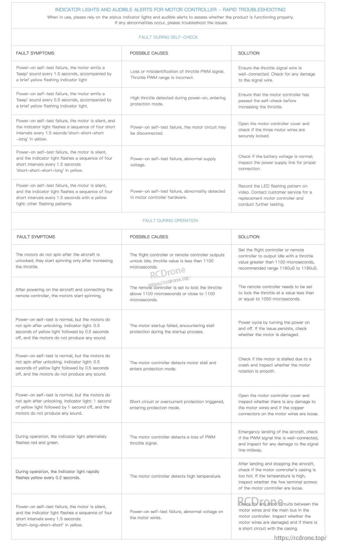
Motor controller LED flash patterns and audible beeps provide quick guidance on likely faults and recommended checks.
Related Collections