BETAFPV SuperP 14CH Diversity Receiver - ExpressLRS ELRS 2.4GHz/915MHz/868MHz TCXO USB-C PWM CRSF SBUS WiFi Setup
BETAFPV SuperP 14CH Diversity Receiver - ExpressLRS ELRS 2.4GHz/915MHz/868MHz TCXO USB-C PWM CRSF SBUS WiFi Setup
BETAFPV
Couldn't load pickup availability
Overview
BETAFPV SuperP 14CH Diversity Receiver is a true ExpressLRS (ELRS) diversity receiver designed for RC models that need stable, reliable control with multi-channel PWM output. It supports 14 PWM channels and is intended for multirotors, fixed-wing aircraft, helicopters, RC cars, and RC boats. Versions are available for 2.4GHz, 915MHz, and 868MHz frequency bands.
Key Features
- 14 PWM channels (up to 14 servos), plus support for external sensors (e.g., barometer, current sensor) and an RGB light strip interface.
- True diversity design with two complete RF receiver chains (dual SX1280/SX1281 for 2.4GHz, or dual SX1276 for 915MHz/868MHz).
- TCXO oscillator shared by two RF chips for an accurate clock source (temperature-compensated crystal oscillator).
- Two antennas (2x U.FL) for diversity reception; separate and vertical placement is recommended for improved signal.
- ExpressLRS firmware: default ExpressLRS V3.3.0.
- USB Type-C port reserved for firmware flashing.
- Failsafe function supported.
- Supported protocols: PWM, CRSF, SBUS; I2C (IIC) also supported for external devices.
Specifications
| Item | BETAFPV SuperP 14CH Diversity Receiver | ELRS 2.4GHz/915MHz/868MHz |
| MCU / RF (2.4GHz version) | ESP32 Pico D4 + 2*SX1280/SX1281 + 2*AT2401C |
| MCU / RF (915MHz/868MHz version) | ESP32 Pico D4 + 2*SX1276 |
| Telemetry Power | 20dBm/100mW (2.4GHz), 17dBm/50mW (915MHz/868MHz) |
| Frequency Bands | 2.4GHz ISM, 915MHz FCC / 868MHz EU |
| Rated Current | 180mA@5V (2.4GHz), 140mA@5V (915MHz/868MHz) |
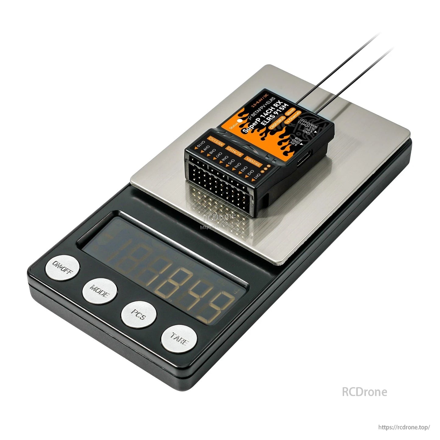
| Weight | 15.5g (2.4GHz), 15.8g (915MHz/868MHz) |
| Default Firmware Version | ExpressLRS V3.3.0 |
| Serial Output Protocol | PWM, CRSF or SBUS |
| Antenna | 2* U.FL Antenna |
| Size | 46.9mm*32.7mm*14.6mm |
| Input Voltage | 3.5V~8.4V DC |
| Voltage Detector Range | 1~6S |
| PWM Channel | 14 Channels |
| Adapted RC Model Type | Multirotors, Fixed-wing aircraft, Helicopters, RC Cars, RC Boats and etc. |
Power note: This receiver accepts 3.5~8.4V. For many servo setups, a 2S battery or above may need to be converted to 5V using a BEC before being connected.
For installation or version selection help (2.4GHz vs 915MHz/868MHz), contact https://rcdrone.top/ or email [email protected].
RGB Status Indication
| RGB Color | Status | Description |
| Rainbow | Fade effect | Power on |
| Green | Slow flash | WIFI upgrading mode |
| Red | Quick flash | No RF chip detected |
| Orange | Double flash | Binding mode |
| Orange | Triple flash | Connected, but mismatched model-match configuration |
| Orange | Slow flash | Waiting for connection |
| Solid on | Connected and color indicates packet rate |
Packet-rate notes: F1000 and F500 are packet rates in FLRC mode (lower latency with shorter reception distance than normal LoRa mode). D500 and D250 are packet rates in DVDA (Deja Vu Diversity Aid) mode; D500 and D250 indicate the same data packet is sent twice and four times respectively. D50 is an exclusive mode under ELRS 900M, sending packets four times repeatedly under 200Hz LoRa mode; receiving distance is equivalent to 200Hz. 100Hz Full achieves 16-channel full resolution output at the 200Hz packet rates of LoRa mode; receiving distance is equivalent to 200Hz.
Port Configuration
Enter the configuration page via WiFi mode:
- Power on the receiver and wait for 60 seconds without binding to any transmitted equipment.
- Once the RGB indicator is in slow green flashing, the receiver's WiFi has been activated.
- Connect WiFi via cellphone or PC (WiFi name: ExpressLRS RX, password shown as expresslrs / ExpressLRS in the provided instructions).
- Open: http://10.0.0.1/hardware.html
On the configuration page, users can set the PWM pin, CRSF pin, I2C pin, etc. The pin number corresponds to specified channels.
Note: Please do not modify other function pins.
Pin Mapping
| Pin | 13 | 15 | 2 | 0 | 4 | 9 | 10 | 5 |
| Main | CH1 | CH2 | CH3 | CH4 | CH5 | CH6 | CH7 | CH8 |
| Second | ||||||||
| Pin | 18 | 23 | 19 | 22 | 3 | 1 | 21 | 36 |
| Main | CH9 | CH10 | CH11 | CH12 | CH13 | CH14 | RGB | VBAT |
| Second | SCL | SDA | RX | TX | ||||
| Third | SBUS |
- VBAT is the battery voltage detection port, supporting 1~6S battery voltage detection.
- When configured to use CRSF output, CH13 becomes RX and CH14 becomes TX.
- When configured to use SBUS output, CH13 has no output, and CH14 becomes SBUS.
- Factory default: CH11 and CH12 are configured as I2C serial ports; at this time, CH13 becomes CH11 and CH14 becomes CH12.
Binding Procedure
The default firmware uses ExpressLRS V3.3.0 protocol and has no preset binding phrase. The transmitter module firmware must be ExpressLRS V3.0.0 or later. Both the receiver and transmitter module should not have any binding phrase.
- Power on and off the receiver 3 times, pausing 2 seconds each step to enter binding mode.
- When the indicator fast blinks with orange twice, the receiver is in binding mode.
- Enter the radio or transmitter module binding mode; when the indicator turns solid, binding is successful.
Note: After successful binding, the receiver will record the device and future binding will be automatic.
Failsafe and Channel Output Settings
WiFi method:
- After the receiver is powered on, wait for 60 seconds without connecting the remote control.
- The RGB indicator enters the green slow flashing state, and the receiver automatically turns on WiFi (WiFi name: ExpressLRS RX, WiFi password: ExpressLRS).
- Use a mobile phone or computer to connect to WiFi, and log in to http://10.0.0.1 with a browser to find the model page.
Failsafe settings note: Do not click “Reverse”. If “750us” is selected, the failsafe value needs to be halved. When the failsafe value is greater than 1500, the mode will automatically switch to “On/Off” mode.
Channel output mode descriptions:
- 50-400Hz: output PWM signal frequency
- 10KHzDuty: used to directly drive micro-motors
- ON/OFF: output high-level or low level
- Serial TX/RX: serial communication port
I2C/CRSF/SBUS output settings:
- I2C output: set channel 11 to I2C SCL and set channel 12 to I2C SDA
- CRSF/SBUS output: set channel 13 to serial RX or set channel 14 to Serial TX
- Supported Serial Protocol (as listed): CRSF, SBUS, SUMD, DJI RS Pro, HoTT Telemetry
- Set the baud rate on the options page (SBUS serial protocol cannot set the baud rate)
- Click “SAVE&REBOOT” to complete the CRSF/SBUS output setup
Applications
- Fixed-wing aircraft
- Helicopters
- Multirotors
- RC cars
- RC boats
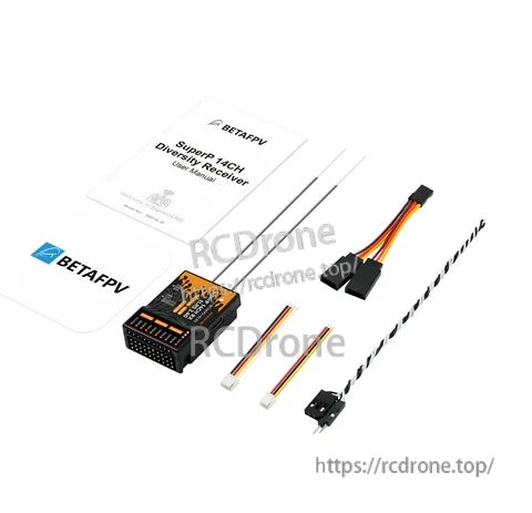
What’s Included
- 1 * SuperP 14CH Diversity Receiver (2.4GHz/915MHz/868MHz)
- 2 * 150mm Monopole Antenna (2.4GHz)
- 2 * 150mm Dipole T Antenna (915MHz/868MHz)
- 1 * GH2.0 3-Pin Cable
- 1 * GH2.0 4-Pin Cable
- 1 * Y Splitter Cable for Servo
- 1 * Voltage Test Cable
- 1 * User Manual
Manuals
- User manual (download)
- Firmware flashing guide / firmware download
- VBAT voltage adjustment method
- TCXO / crystal frequency error reference
Details
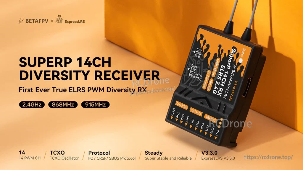
True ExpressLRS diversity receiver with up to 14 PWM channels for stable control across multiple RC platforms.
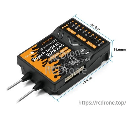
A compact 46.9 × 32.7 × 14.6 mm footprint makes it easier to fit in tight airframes and enclosures.
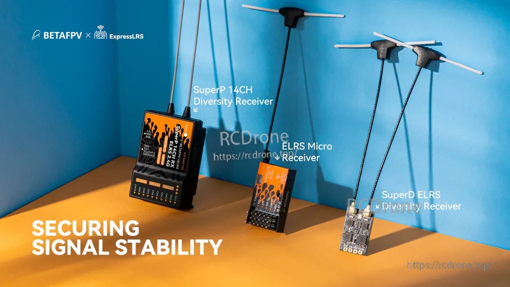
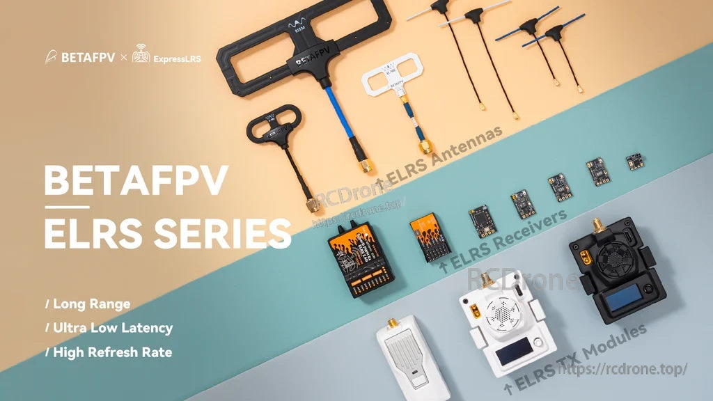
Receiver sizing across the ELRS lineup helps match your build to the channel count and diversity needs.

Designed for multirotors, fixed-wing, helicopters, RC cars, and RC boats that need multi-channel PWM control.
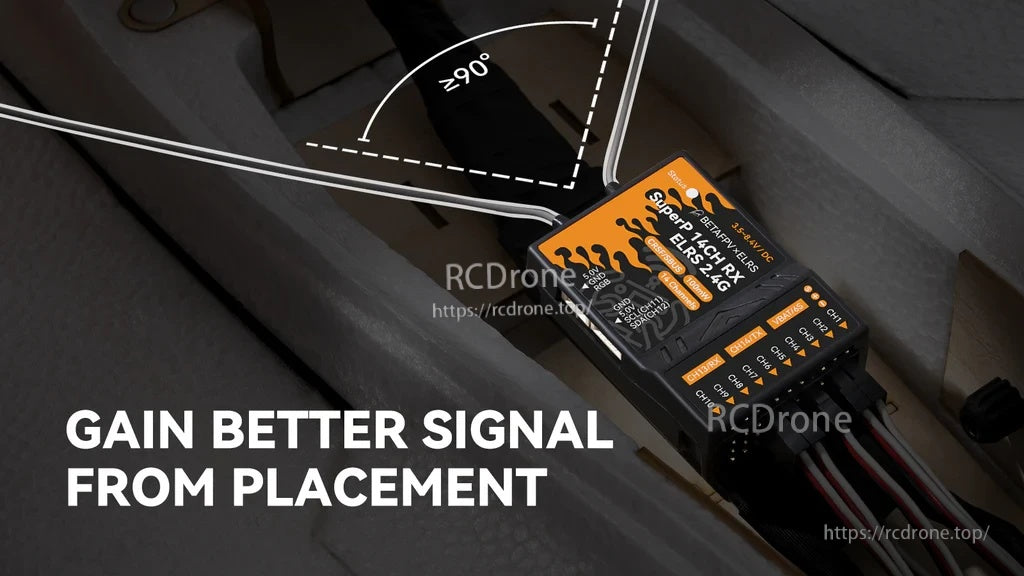
Separate the two antennas and keep them at roughly 90° for more consistent reception in different orientations.
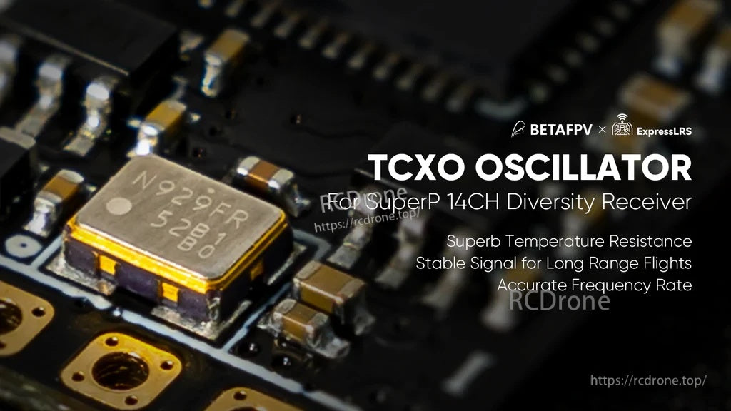
A TCXO provides a more accurate clock source to help maintain reliable links over temperature changes.
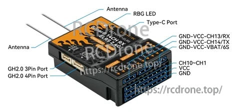
Clearly labeled connectors support PWM outputs, external device connections, and USB‑C firmware flashing.


Included accessories cover basic wiring and antenna setup so you can start installation right away.