Yahboom ESP32-S3 WiFi ক্যামেরা মডিউল লাইট ভার্সন ২MP AI ভিশন বোর্ড, AP+STA, UART/IIC, টাইপ-C
Yahboom ESP32-S3 WiFi ক্যামেরা মডিউল লাইট ভার্সন ২MP AI ভিশন বোর্ড, AP+STA, UART/IIC, টাইপ-C
Yahboom
পিকআপের উপলভ্যতা লোড করা যায়নি
ওভারভিউ
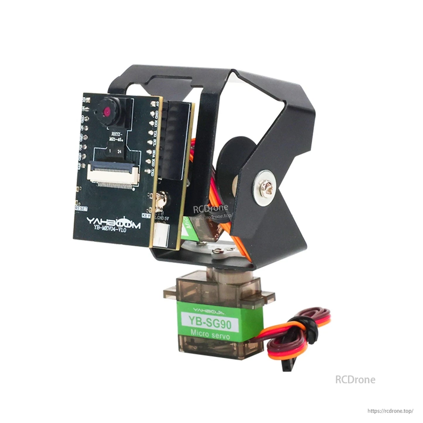
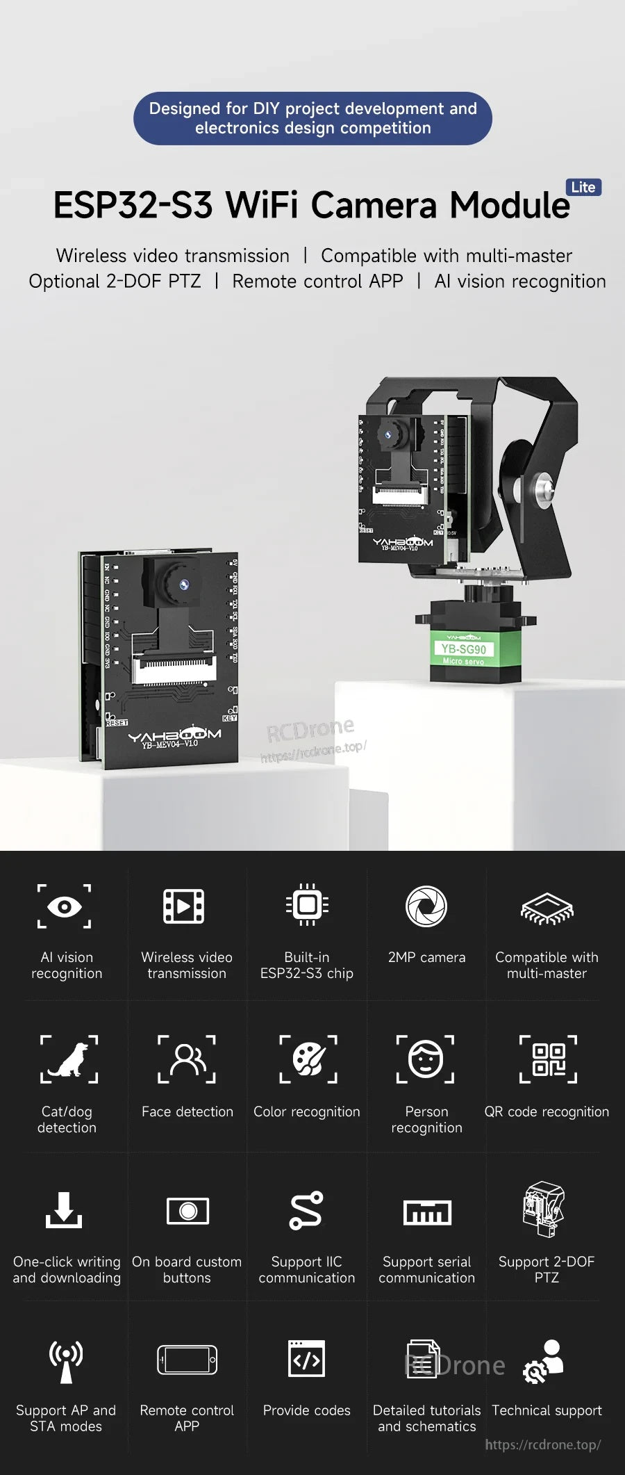
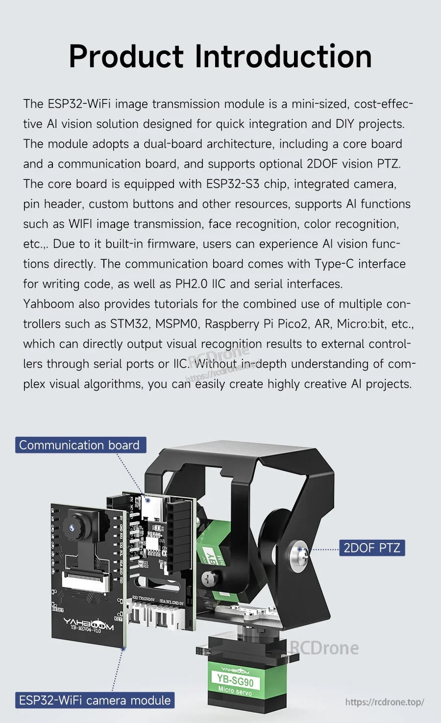
ESP32 WiFi ক্যামেরা মডিউল লাইট ভার্সন হল DIY প্রকল্প উন্নয়ন এবং ইলেকট্রনিক্স ডিজাইন প্রতিযোগিতার জন্য একটি ESP32-S3-ভিত্তিক AI ভিশন সমাধান। এটি WiFi/BT (BT 5.0), একটি অনবোর্ড 2MP CMOS ক্যামেরা, অ্যান্টেনা সাপোর্ট, কাস্টম বোতাম এবং সিরিয়াল + IIC ইন্টারফেস সমন্বিত। মডিউলটি তার নিজস্ব হটস্পটের মাধ্যমে LAN এর উপর ওয়্যারলেস ভিডিও ট্রান্সমিশনের জন্য একটি ন্যূনতম সিস্টেম বোর্ড হিসাবে কাজ করতে পারে বা একটি রাউটার নেটওয়ার্কের সাথে সংযোগ করতে পারে, এবং এটি একটি স্মার্ট গাড়ি বা রোবটে ইনস্টল করা যেতে পারে একটি ঐচ্ছিক 2-DOF PTZ সহ রিয়েল-টাইম ভিডিও ট্রান্সমিশন এবং AI ভিজ্যুয়াল স্বীকৃতির জন্য।
একটি ডুয়াল-বোর্ড আর্কিটেকচার সমর্থিত (কোর বোর্ড + ঐচ্ছিক যোগাযোগ বোর্ড)। যোগাযোগ বোর্ড কোড লেখার জন্য একটি টাইপ-সি ইন্টারফেস এবং PH2.0 IIC এবং সিরিয়াল ইন্টারফেস প্রদান করে।
পণ্য প্রশ্ন বা ইন্টিগ্রেশন সহায়তার জন্য, যোগাযোগ করুন https://rcdrone.top/ অথবা ইমেইল করুন [email protected].
মূল বৈশিষ্ট্যসমূহ
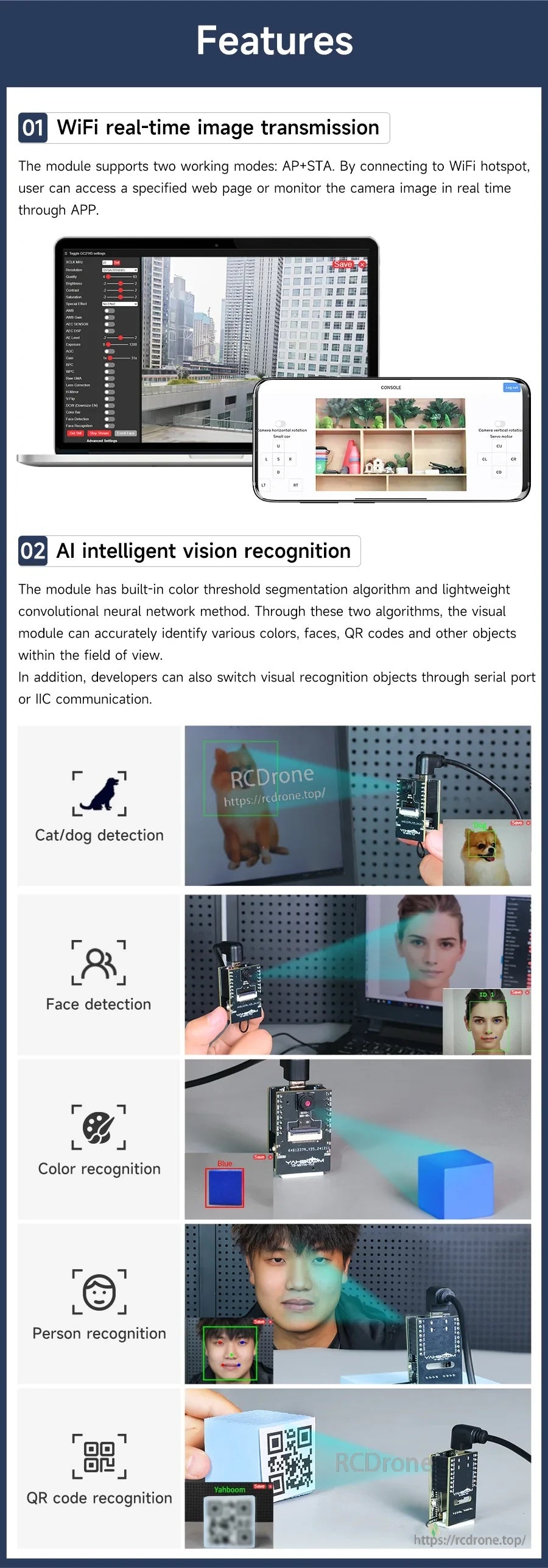
- ওয়্যারলেস ভিডিও ট্রান্সমিশন; ওয়েব ক্যামেরা মনিটরিং এবং অ্যাপ ভিউয়িং সমর্থন করে।
- দুটি কাজের মোড: AP মোড (মডিউল স্বয়ংক্রিয়ভাবে ওয়াইফাই হটস্পট পাঠায়) এবং STA মোড (মডিউল ওয়াইফাই রাউটারের সাথে সংযুক্ত)। AP+STA পরিবর্তন করা যায়, এবং প্রয়োগের প্রয়োজন অনুযায়ী একই সময়ে সক্রিয় করা যায়।
- এআই ইন্টেলিজেন্ট ভিশন রিকগনিশন (বিল্ট-ইন অ্যালগরিদম): বিড়াল/কুকুর সনাক্তকরণ, মুখ সনাক্তকরণ, রঙ সনাক্তকরণ, ব্যক্তি সনাক্তকরণ, কিউআর কোড সনাক্তকরণ।
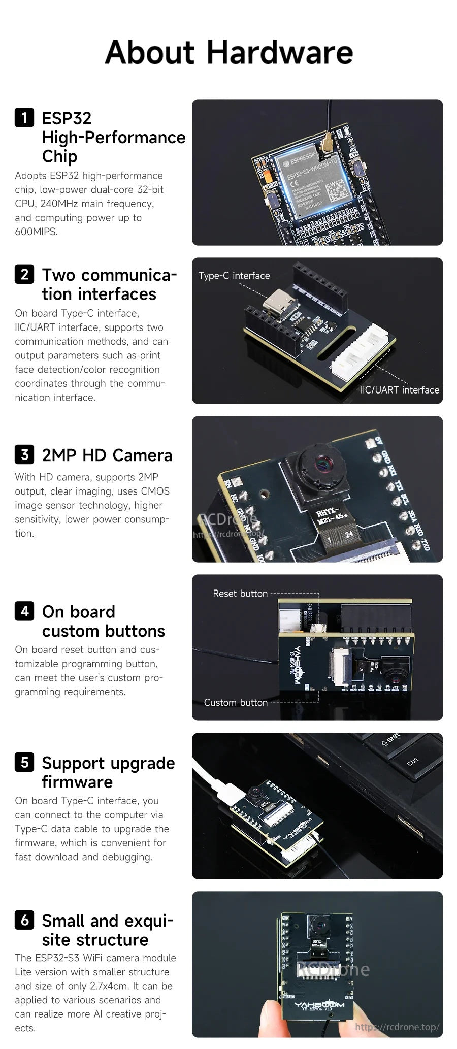
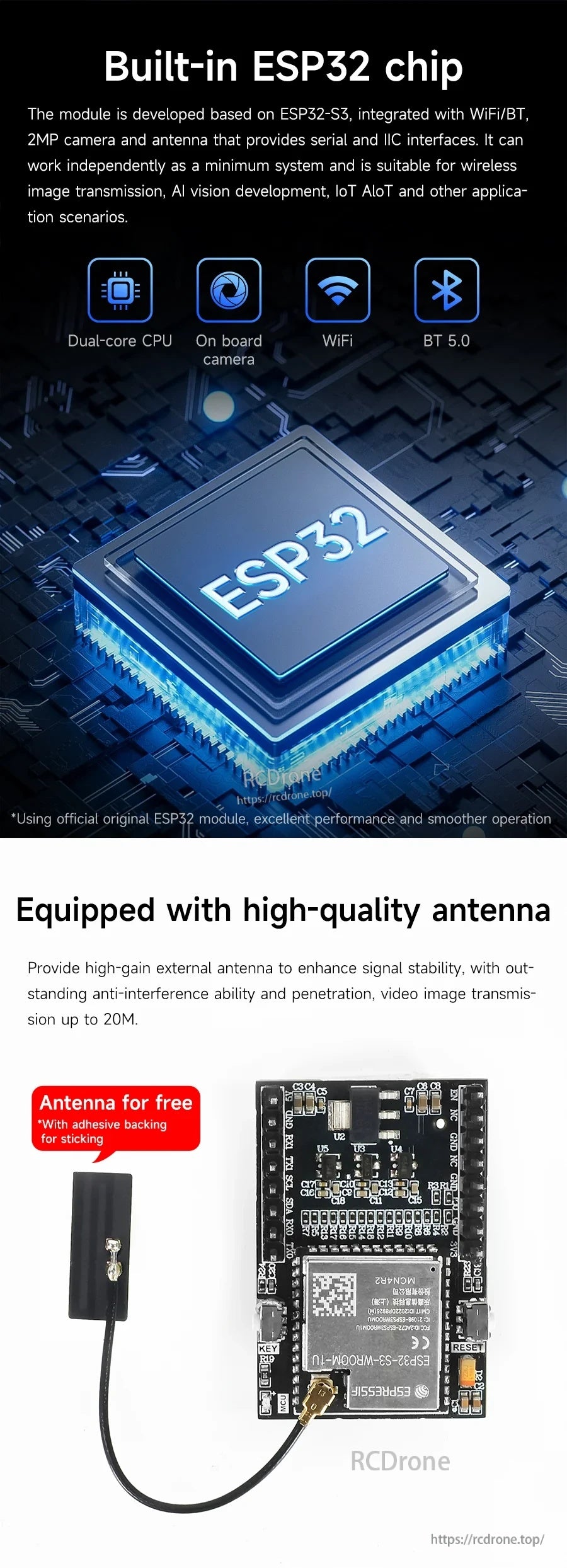
- বিল্ট-ইন ESP32-S3 চিপ: লো-পাওয়ার ডুয়াল-কোর 32-বিট সিপিইউ, সর্বাধিক 240MHz প্রধান ফ্রিকোয়েন্সি, প্রায় 600MIPS কম্পিউটিং ক্ষমতা।
- 2MP এইচডি ক্যামেরা আউটপুট; CMOS ইমেজ সেন্সর প্রযুক্তি।
- ইন্টারফেস: সিরিয়াল যোগাযোগ এবং IIC যোগাযোগ (IIC/UART ইন্টারফেস উল্লেখিত); সনাক্তকরণ বস্তুগুলি সিরিয়াল পোর্ট বা IIC যোগাযোগের মাধ্যমে পরিবর্তন করা যায়।
- অনবোর্ড কাস্টম বোতাম: রিসেট বোতাম এবং কাস্টমাইজযোগ্য প্রোগ্রামিং বোতাম।
- ফার্মওয়্যার আপডেট সমর্থন: টাইপ-সি (যোগাযোগ বোর্ড সহ) বা ইউএসবি-টু-টিটিএল মডিউল (আলাদা মডিউল) এর মাধ্যমে।
- বাহ্যিক অ্যান্টেনা সমর্থন; ভিডিও ইমেজ ট্রান্সমিশন 20M পর্যন্ত (যেমন বলা হয়েছে)।
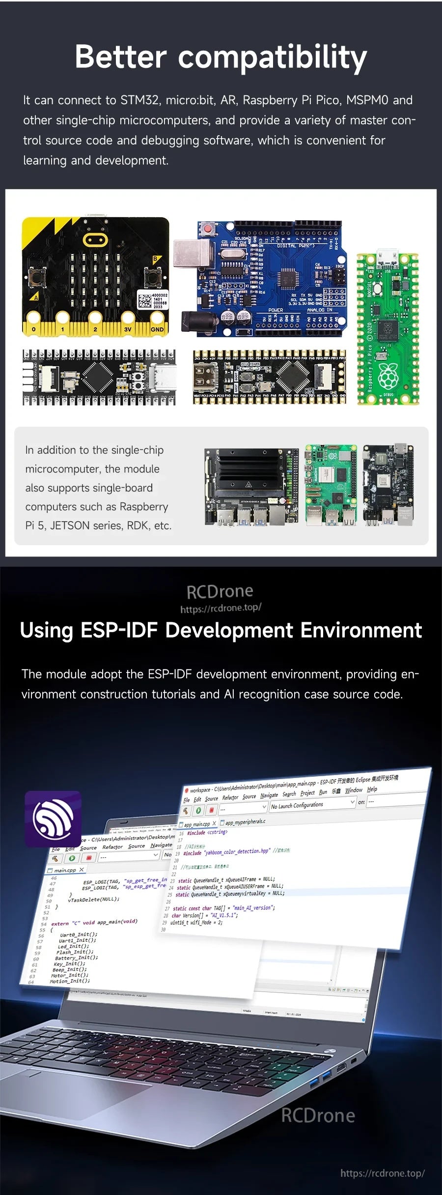
- মাল্টি-মাস্টার এর সাথে সামঞ্জস্যপূর্ণ (একাধিক বাহ্যিক মাস্টার কন্ট্রোল সমর্থন করে); একাধিক এমসিইউ (STM32, মাইক্রো:বিট, AR, রাস্পবেরি পাই পিকো, MSPM0, ইত্যাদি) এর জন্য টিউটোরিয়াল।
- উন্নয়ন সমর্থন: কোড, বিস্তারিত টিউটোরিয়াল এবং স্কিমেটিক প্রদান করে; ESP-IDF উন্নয়ন পরিবেশ টিউটোরিয়াল এবং AI স্বীকৃতি কেস সোর্স কোড।
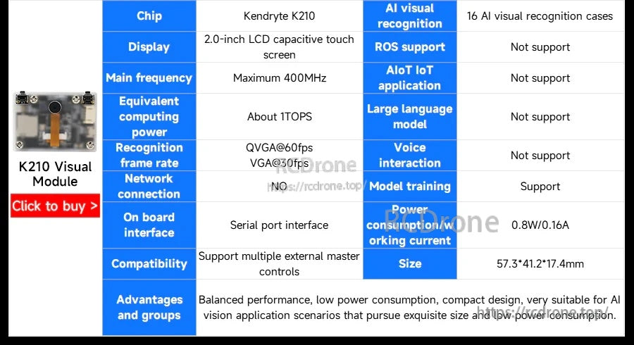
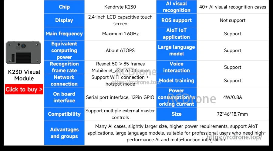
স্পেসিফিকেশন
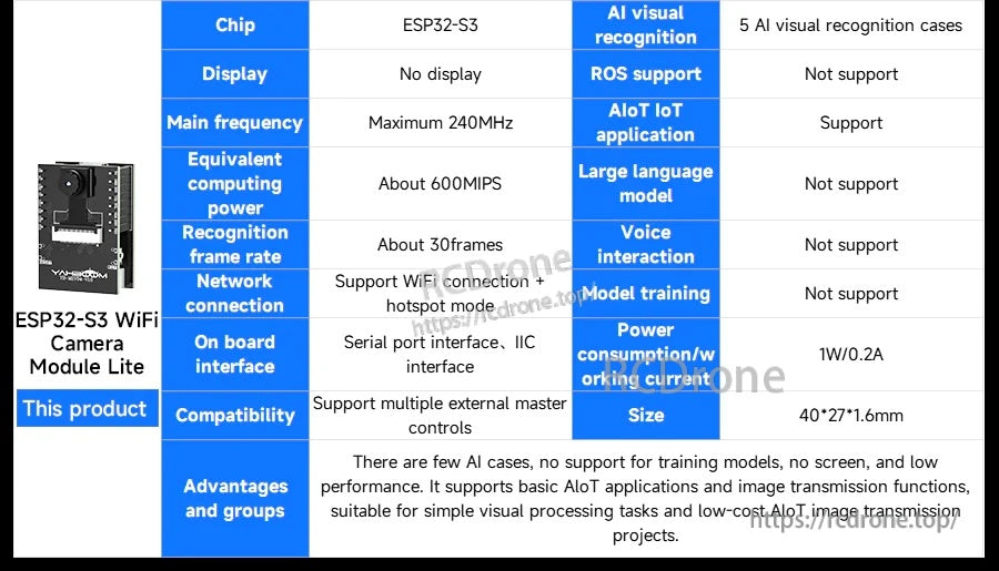
| চিপ | ESP32-S3 |
| সিপিইউ | লো-পাওয়ার ডুয়াল-কোর ৩২-বিট |
| প্রধান ফ্রিকোয়েন্সি | সর্বাধিক ২৪০MHz |
| সমমানের গণনা ক্ষমতা | প্রায় ৬০০MIPS |
| স্বীকৃতি ফ্রেম রেট | প্রায় ৩০ফ্রেম |
| ডিসপ্লে | কোনো ডিসপ্লে নেই |
| ক্যামেরা | ২MP (CMOS ইমেজ সেন্সর প্রযুক্তি) |
| ওয়্যারলেস | WiFi + BT 5.0 |
| নেটওয়ার্ক সংযোগ | WiFi সংযোগ + হটস্পট মোড সমর্থন করে |
| অন বোর্ড ইন্টারফেস | সিরিয়াল পোর্ট ইন্টারফেস, IIC ইন্টারফেস |
| AI ভিজ্যুয়াল স্বীকৃতি | 5 AI ভিজ্যুয়াল স্বীকৃতি কেস |
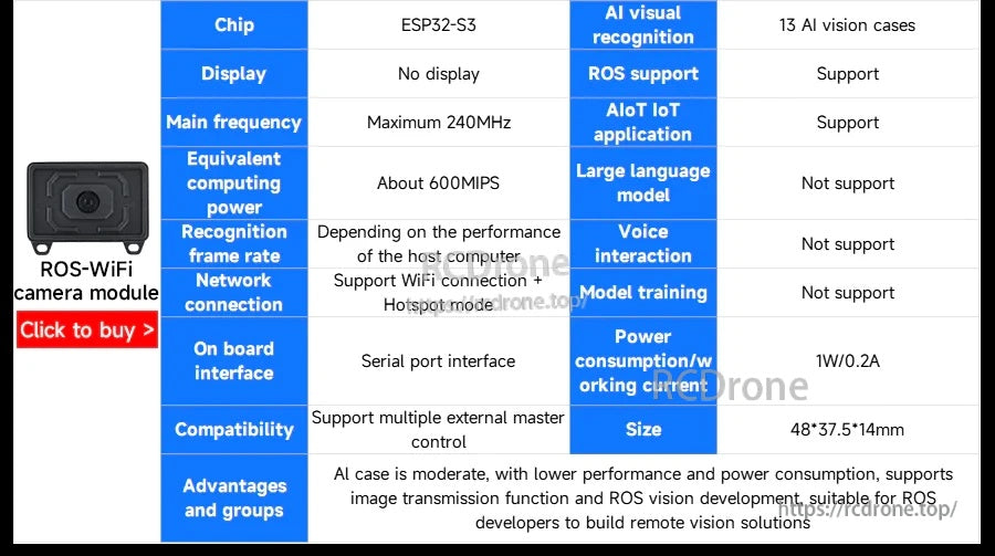
| ROS সমর্থন | সমর্থন করে না |
| AIoT IoT অ্যাপ্লিকেশন | সমর্থন করে |
| বড় ভাষার মডেল | সমর্থন করে না |
| ভয়েস ইন্টারঅ্যাকশন | সমর্থন করে না |
| মডেল প্রশিক্ষণ | সমর্থন করে না |
| বিদ্যুৎ খরচ / কাজের বর্তমান | 1W / 0.2A |
| আকার | 40*27*1.6mm (এছাড়াও 2 হিসাবে উল্লেখ করা হয়েছে।7x4cm) |
নেটওয়ার্ক মোড
- এপি মোড: ফোন/কম্পিউটার বিল্ট-ইন ওয়াইফাই হটস্পটে সংযুক্ত হয়ে মোবাইল অ্যাপ বা ওয়েব পেজের মাধ্যমে ভিডিও স্ট্রিম রিয়েল টাইমে দেখতে পারে।
- এসটিএ মোড: সিরিয়াল পোর্ট কনফিগারেশনের মাধ্যমে ব্যবহারকারীর ওয়াইফাই নেটওয়ার্কে সংযুক্ত হয়ে মোবাইল অ্যাপ বা ওয়েব পেজের মাধ্যমে ভিডিও স্ট্রিম রিয়েল টাইমে দেখতে পারে।
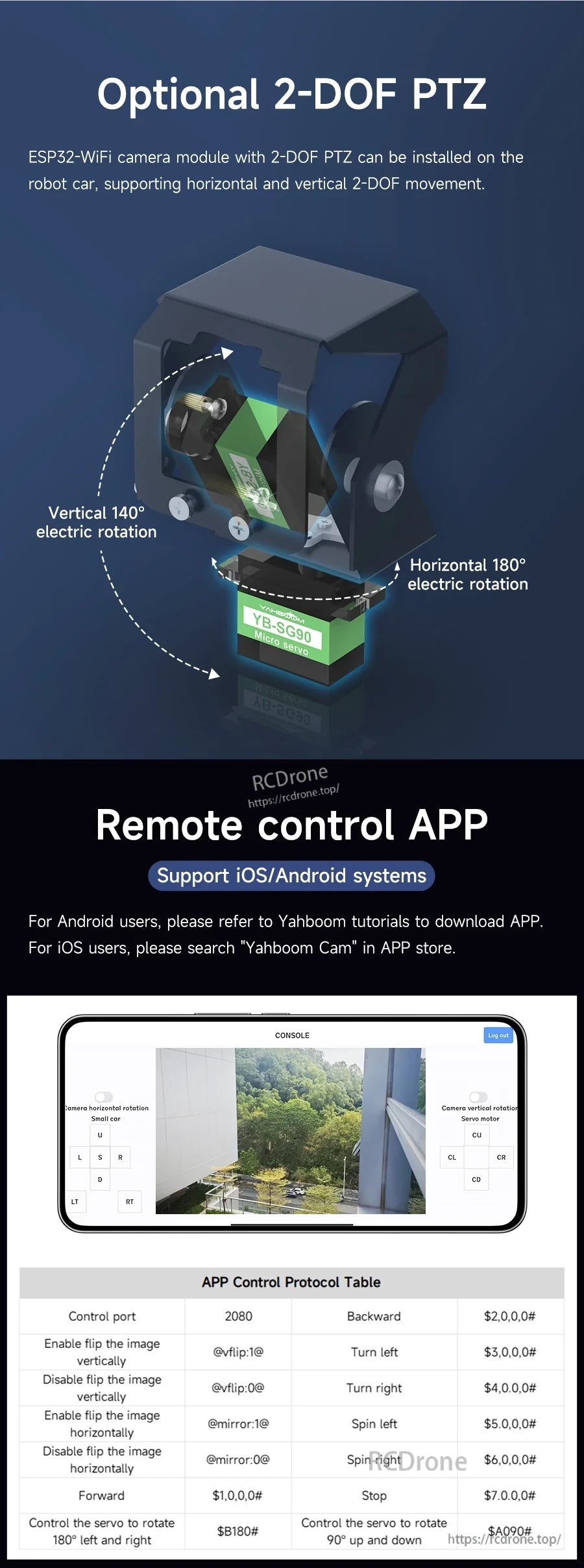
অ্যাপ নিয়ন্ত্রণ
রিমোট কন্ট্রোল অ্যাপ: iOS/Android সিস্টেম সমর্থন করে। iOS ব্যবহারকারীরা অ্যাপ স্টোরে "Yahboom Cam" অনুসন্ধান করতে পারেন (যেমন বলা হয়েছে)।
অ্যাপ নিয়ন্ত্রণ প্রোটোকল টেবিল
| নিয়ন্ত্রণ পোর্ট | ২০৮০ |
| ছবিটি উল্লম্বভাবে উল্টানোর অনুমতি দিন | @vflip:1@ |
| ছবিটি উল্লম্বভাবে উল্টানো নিষ্ক্রিয় করুন | @vflip:0@ |
| ছবিটি অনুভূমিকভাবে উল্টানোর অনুমতি দিন | @mirror:1@ |
| ছবিটি অনুভূমিকভাবে উল্টানো নিষ্ক্রিয় করুন | @mirror:0@ |
| সামনে | $1,0,0# |
| পিছনে | $2,0,0# |
| বামে ঘুরুন | $3,0,0# |
| ডানে ঘুরুন | $4,0,0# |
| বামে ঘুরান | $5,0,0# |
| ডানে ঘুরান | $6,0,0# |
| থামুন | $7.0.0# |
| সার্ভোকে ১৮০° বামে এবং ডানে ঘোরানোর নিয়ন্ত্রণ করুন | $B180# |
| সার্ভোকে ৯০° উপরে এবং নিচে ঘোরানোর নিয়ন্ত্রণ করুন | $A090# |
ঐচ্ছিক ২-ডিওএফ পিটিজেড
- রোবট কার ইনস্টলেশনের জন্য অনুভূমিক এবং উল্লম্ব ২-ডিওএফ গতিবিধি সমর্থন করে।
- উল্লম্ব ১৪০° বৈদ্যুতিক ঘূর্ণন; অনুভূমিক ১৮০° বৈদ্যুতিক ঘূর্ণন।
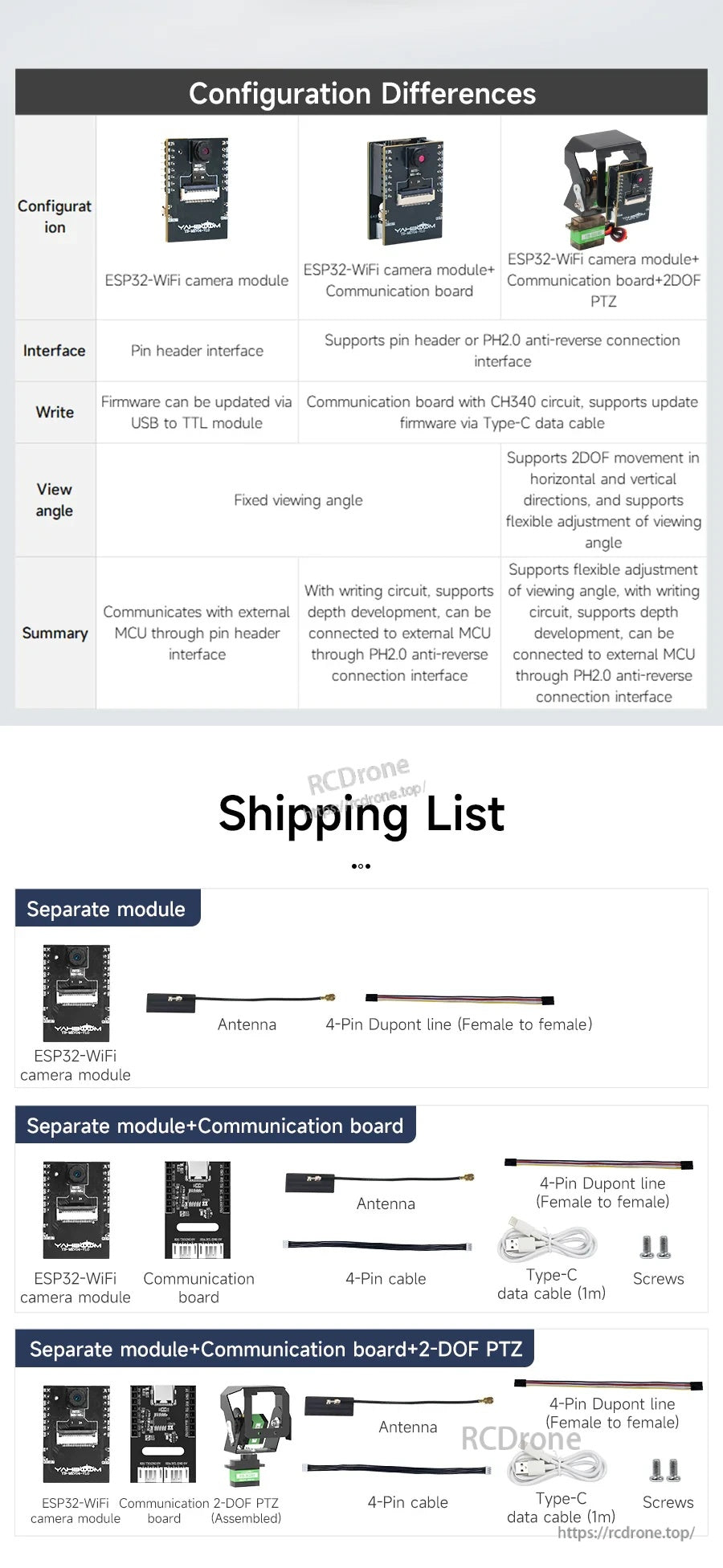
কনফিগারেশন পার্থক্য
| কনফিগারেশন | ESP32-WiFi ক্যামেরা মডিউল | ESP32-WiFi ক্যামেরা মডিউল + যোগাযোগ বোর্ড | ESP32-WiFi ক্যামেরা মডিউল + যোগাযোগ বোর্ড + 2DOF পিটিজেড |
| ইন্টারফেস | পিন হেডার ইন্টারফেস | পিন হেডার বা PH2 সমর্থন করে।0 অ্যান্টি-রিভার্স সংযোগ ইন্টারফেস | |
| লিখুন | ফার্মওয়্যার USB থেকে TTL মডিউলের মাধ্যমে আপডেট করা যেতে পারে | CH340 সার্কিট সহ যোগাযোগ বোর্ড, টাইপ-C ডেটা কেবলের মাধ্যমে ফার্মওয়্যার আপডেট সমর্থন করে | |
| দৃশ্য কোণ | স্থির দৃশ্য কোণ | অনুভূমিক এবং উল্লম্ব দিকনির্দেশে 2DOF আন্দোলন সমর্থন করে, এবং দৃশ্য কোণের নমনীয় সমন্বয় সমর্থন করে | |
| সারাংশ | পিন হেডার ইন্টারফেসের মাধ্যমে বাহ্যিক MCU এর সাথে যোগাযোগ করে | লেখার সার্কিট সহ, গভীর উন্নয়ন সমর্থন করে, PH2.0 অ্যান্টি-রিভার্স সংযোগ ইন্টারফেসের মাধ্যমে বাহ্যিক MCU এর সাথে সংযুক্ত করা যেতে পারে | দৃশ্য কোণের নমনীয় সমন্বয় সমর্থন করে, লেখার সার্কিট সহ, গভীর উন্নয়ন সমর্থন করে, PH2.0 অ্যান্টি-রিভার্স সংযোগ ইন্টারফেস |
কি অন্তর্ভুক্ত আছে
আলাদা মডিউল
- ESP32-WiFi ক্যামেরা মডিউল
- অ্যান্টেনা
- 4-পিন ডুপন্ট লাইন (মহিলা থেকে মহিলা)
আলাদা মডিউল + যোগাযোগ বোর্ড
- ESP32-WiFi ক্যামেরা মডিউল
- যোগাযোগ বোর্ড
- অ্যান্টেনা
- 4-পিন ডুপন্ট লাইন (মহিলা থেকে মহিলা)
- 4-পিন কেবল
- টাইপ-C ডেটা কেবল (1মি)
- স্ক্রু
আলাদা মডিউল + যোগাযোগ বোর্ড + 2-DOF PTZ
- ESP32-WiFi ক্যামেরা মডিউল
- যোগাযোগ বোর্ড
- 2-DOF PTZ (সংযোজিত)
- অ্যান্টেনা
- 4-পিন ডুপন্ট লাইন (মহিলা থেকে মহিলা)
- 4-পিন কেবল
- টাইপ-C ডেটা কেবল (1মি)
- স্ক্রু
টিউটোরিয়ালস
টিউটোরিয়াল লিঙ্ক: ESP32 WiFi ক্যামেরা মডিউল লাইট ভার্সন
বিস্তারিত
ESP32‑S3 এর উপর ভিত্তি করে তৈরি, এই WiFi/BT ক্যামেরা মডিউলটি DIY রোবট, স্মার্ট গাড়ি এবং এমবেডেড প্রকল্পের জন্য AI ভিশন ফাংশন সহ একটি 2MP সেন্সরকে একত্রিত করে।

একটি ডুয়াল-বোর্ড সেটআপ সমর্থিত: একটি কমপ্যাক্ট ক্যামেরা কোর বোর্ড এবং একটি ঐচ্ছিক টাইপ-সি যোগাযোগ বোর্ড সুবিধাজনক প্রোগ্রামিং এবং সম্প্রসারণের জন্য।
স্বতন্ত্র ক্যামেরা মডিউল নির্বাচন করুন অথবা আপনি কিভাবে এটি প্রোগ্রাম এবং মাউন্ট করতে চান তার উপর নির্ভর করে টাইপ-সি যোগাযোগ বোর্ড এবং ২-ডিওএফ পিটিজেড কিট যোগ করুন।
এটি ওয়াইফাই এর মাধ্যমে রিয়েল-টাইম ভিডিও স্ট্রিমিং এবং কিউআর কোড, মুখমণ্ডল, রং এবং সাধারণ বস্তুগুলির মত বিল্ট-ইন স্বীকৃতি বিকল্পগুলির জন্য ব্যবহার করুন।
অনবোর্ড বোতাম এবং সাধারণ ইন্টারফেস (UART/IIC) ক্যামেরা মডিউলকে কাস্টম কন্ট্রোলার এবং রোবোটিক্স প্ল্যাটফর্মে সংহত করা সহজ করে তোলে।
উন্নয়ন সংস্থানগুলি জনপ্রিয় কন্ট্রোলার এবং ESP‑IDF পরিবেশকে লক্ষ্য করে, ডেমো থেকে পূর্ণ অ্যাপ্লিকেশন পর্যন্ত দ্রুত প্রোটোটাইপিং সমর্থন করে।
বাহ্যিক অ্যান্টেনা সমর্থন ল্যান ভিডিও ট্রান্সমিশন এবং দূরবর্তী পর্যবেক্ষণ ব্যবহারের ক্ষেত্রে বেতার স্থিতিশীলতা উন্নত করতে সহায়তা করে।
ক্যামেরা প্যান/টিল্ট করতে এবং অ্যাপ-ভিত্তিক রিমোট ইন্টারফেসের মাধ্যমে দেখার দিক নিয়ন্ত্রণ করতে 2‑DOF PTZ যোগ করুন।
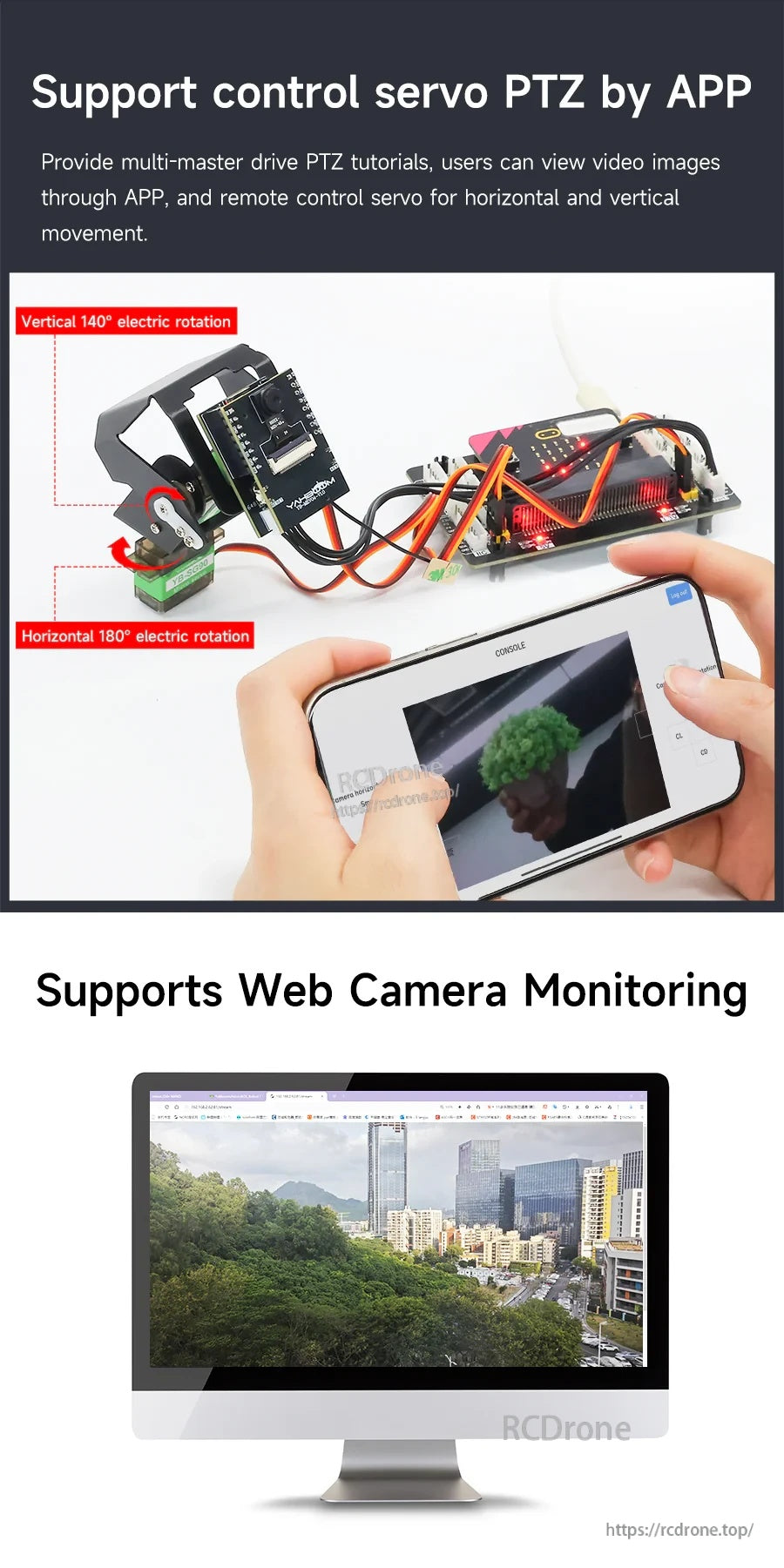
আপনার কাজের ধারা অনুযায়ী দ্রুত পরীক্ষা থেকে ডেস্কটপ ড্যাশবোর্ড পর্যন্ত অ্যাপ ভিউইং এবং ব্রাউজার মনিটরিংয়ের মধ্যে স্যুইচ করুন।

AP মোড একটি সরাসরি হটস্পট সংযোগ তৈরি করে, যখন STA মোড একটি বিদ্যমান রাউটার নেটওয়ার্কে যোগ দেয় নমনীয় স্থাপনার জন্য।
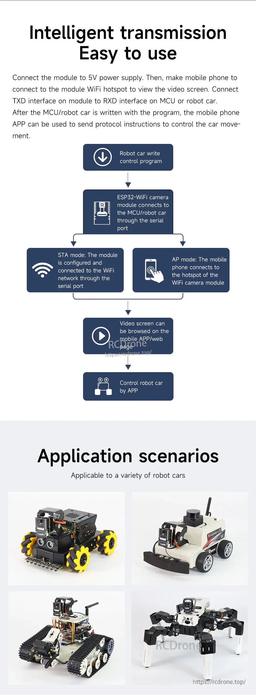
সাধারণ সেটআপগুলি ক্যামেরা স্ট্রিমকে ফোন বা পিসিতে সংযুক্ত করে মনিটরিংয়ের জন্য, যখন একটি পৃথক কন্ট্রোলার সিরিয়াল/IIC কমান্ডের মাধ্যমে রোবটের গতি পরিচালনা করে।
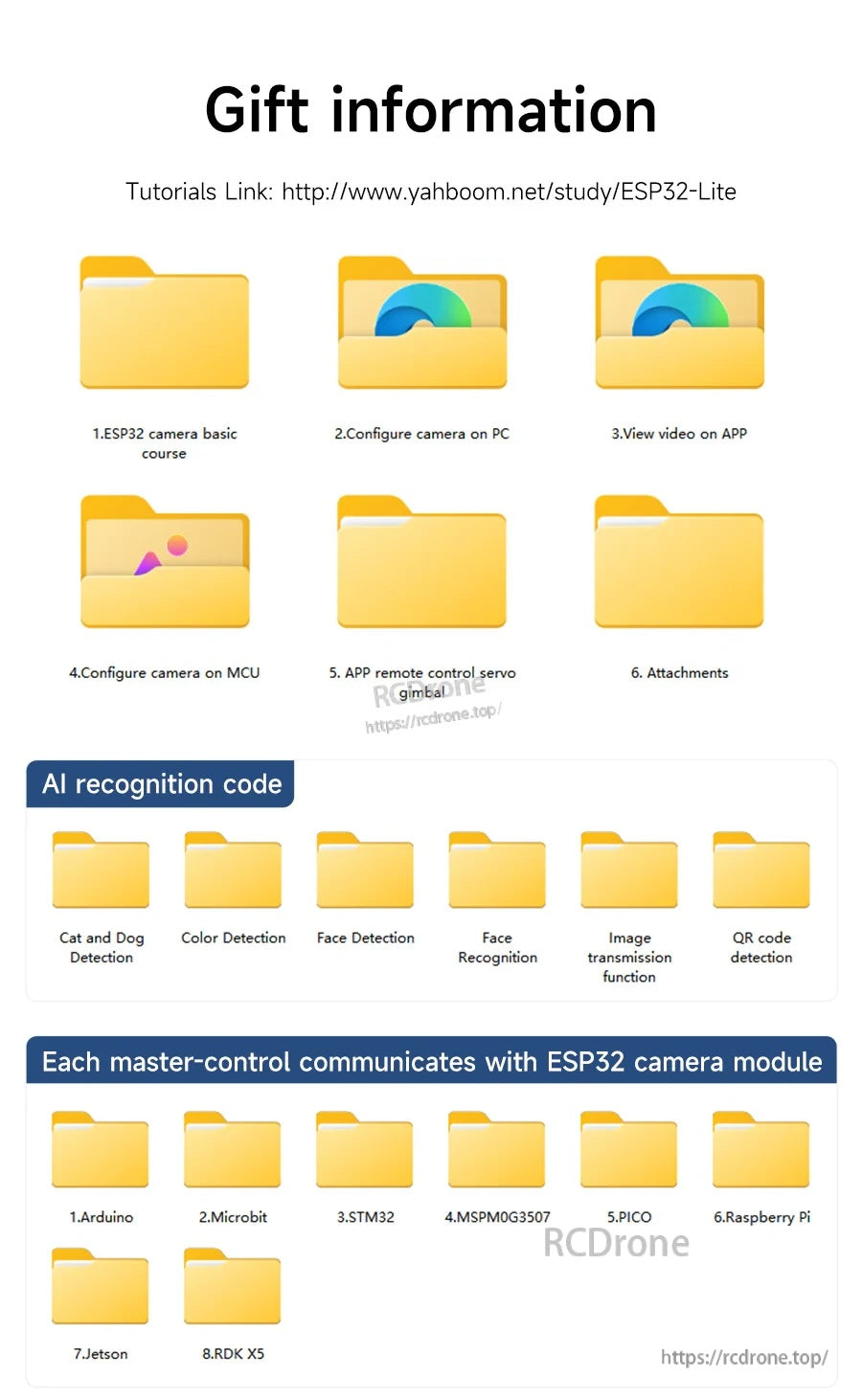
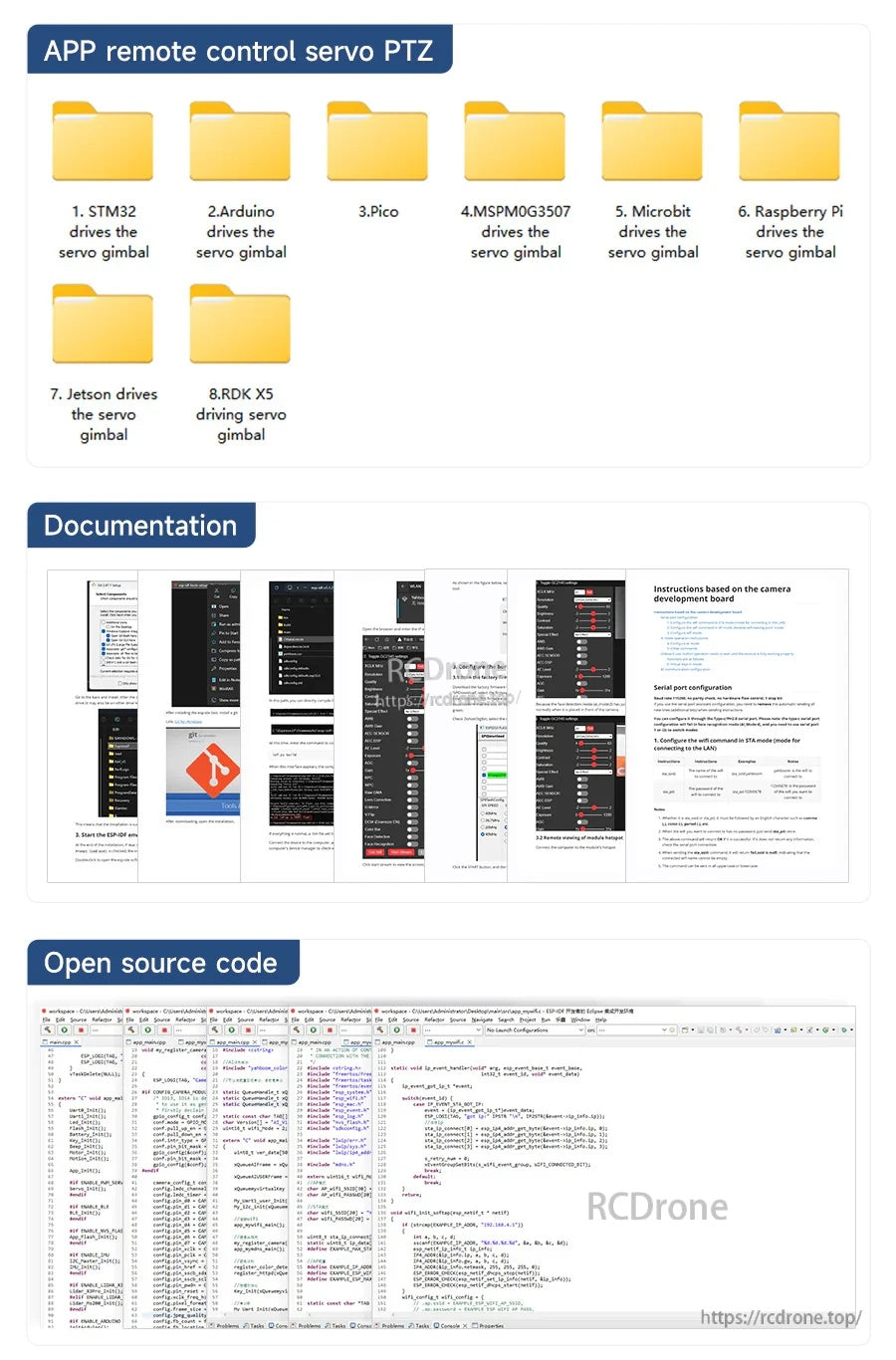
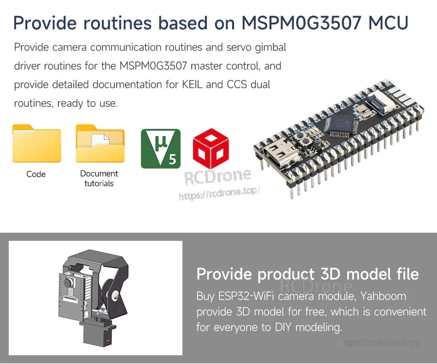
Yahboom ESP32 WiFi ক্যামেরা প্রকল্পগুলি ডাউনলোডযোগ্য কোড, ডকুমেন্টেশন টিউটোরিয়াল এবং DIY নির্মাণের জন্য একটি 3D মডেল ফাইল সহ সমর্থিত।
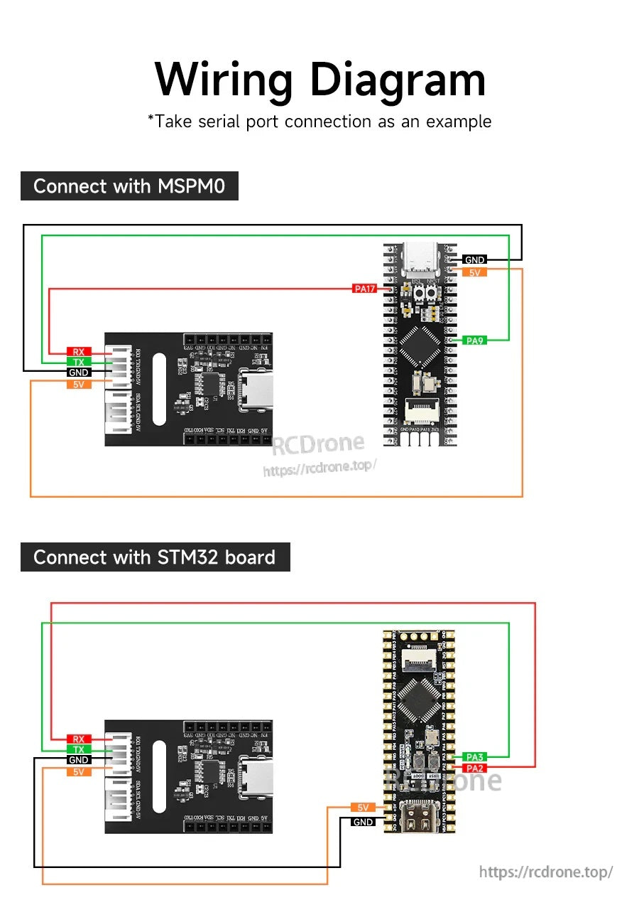
ESP32-S3 WiFi ক্যামেরা MSPM0 বা STM32 কন্ট্রোলারগুলির সাথে 5V, GND, এবং UART TX/RX সিরিয়াল লাইনের মাধ্যমে মৌলিক যোগাযোগের জন্য সংযুক্ত হয়।
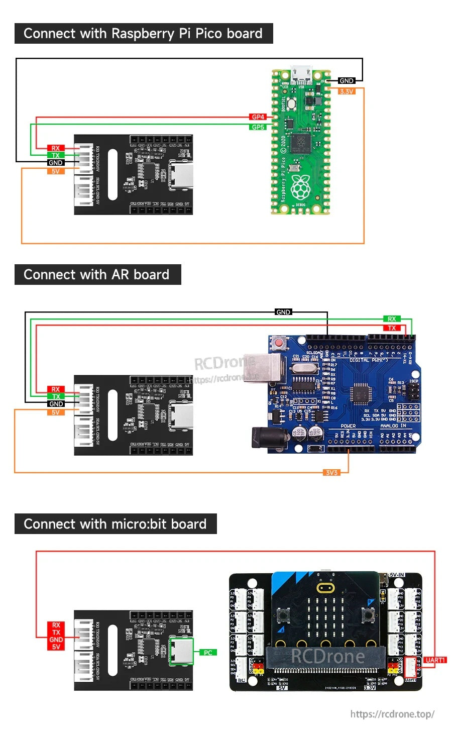
Yahboom ESP32-S3 WiFi ক্যামেরা মডিউলটি TX/RX, পাওয়ার এবং GND সংযোগ ব্যবহার করে Raspberry Pi Pico, Arduino, বা micro:bit এর সাথে সংযুক্ত করা যেতে পারে।
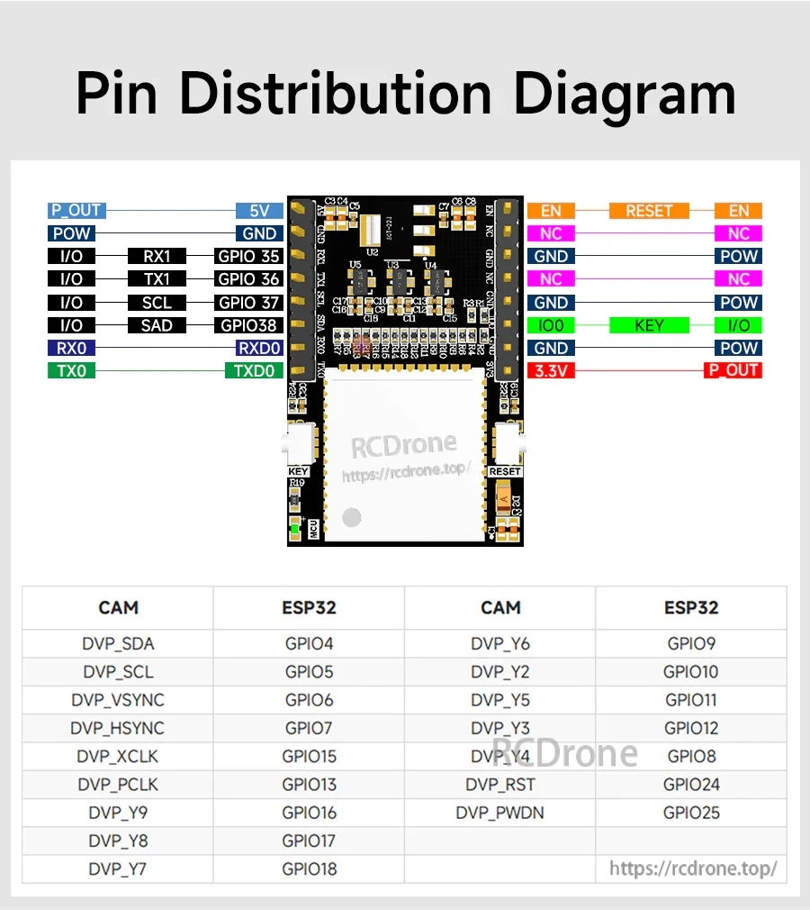
ESP32-S3 WiFi ক্যামেরা মডিউলটিতে 5V/GND পাওয়ার, UART TX/RX, রিসেট এবং ক্যামেরা সিগন্যাল সংযোগের জন্য লেবেলযুক্ত পিনআউট অন্তর্ভুক্ত রয়েছে।
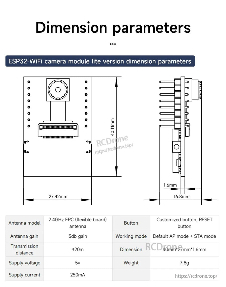
Yahboom ESP32-S3 WiFi ক্যামেরা মডিউলটি 2.4GHz FPC অ্যান্টেনা ব্যবহার করে এবং 5V পাওয়ারে চলে, একটি রিসেট বোতাম এবং AP/STA মোড তালিকাভুক্ত রয়েছে।
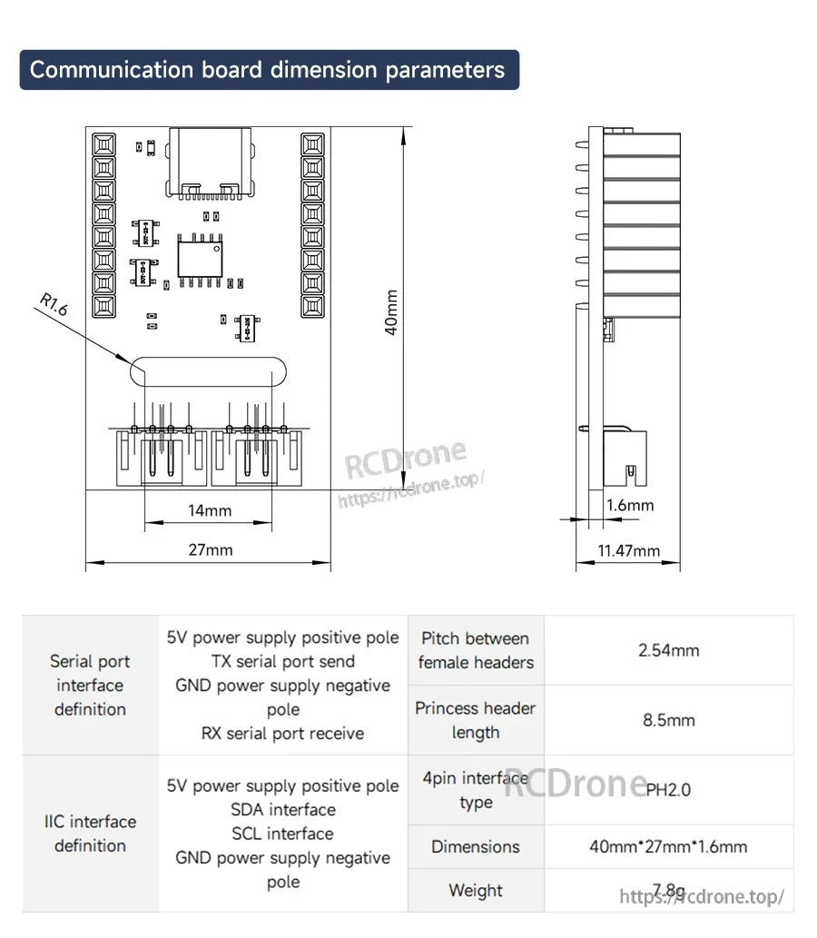
ESP32-S3 ক্যামেরা যোগাযোগ বোর্ডের মাপ 40×27×1.6 মিমি এবং 2.54 মিমি হেডার পিচ ব্যবহার করে, লেবেলযুক্ত 5V/TX/RX/GND এবং 5V/SDA/SCL/GND সংযোগ সহ।
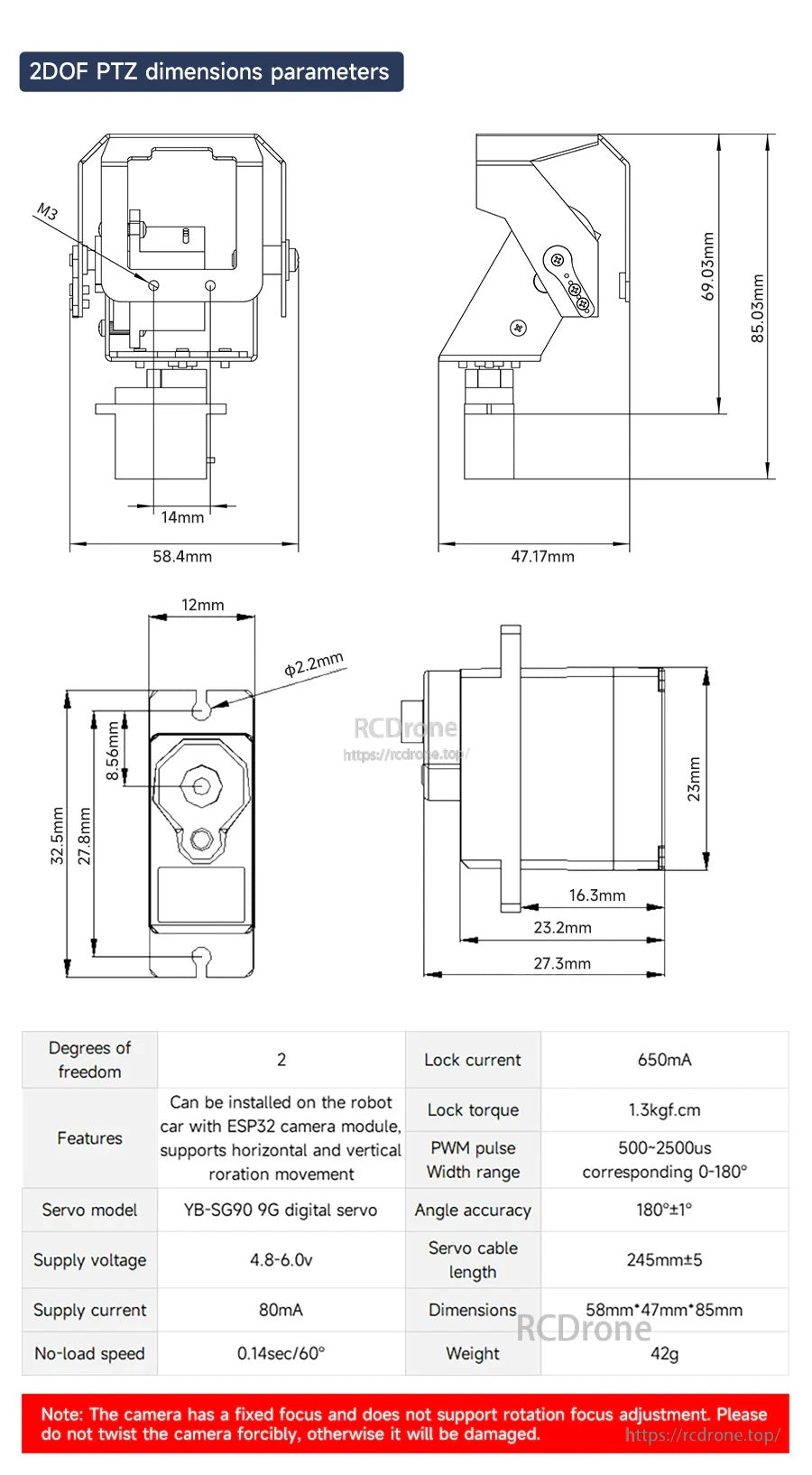
2DOF PTZ মাত্রা এবং তালিকাভুক্ত সার্ভো ভোল্টেজ/কারেন্টের বিবরণ Yahboom ESP32-S3 WiFi ক্যামেরা নির্মাণের জন্য মাউন্টিং স্পেস এবং পাওয়ার পরিকল্পনা করতে সহায়তা করে।
Related Collections