Yahboom MSPM0G3507 মিনি ডেভেলপমেন্ট বোর্ড, টাইপ-সি CH340, SWD, ৪০-পিন GPIO, ১২৮K/৩২K + ৪M
Yahboom MSPM0G3507 মিনি ডেভেলপমেন্ট বোর্ড, টাইপ-সি CH340, SWD, ৪০-পিন GPIO, ১২৮K/৩২K + ৪M
Yahboom
পিকআপের উপলভ্যতা লোড করা যায়নি
সংক্ষিপ্ত বিবরণ
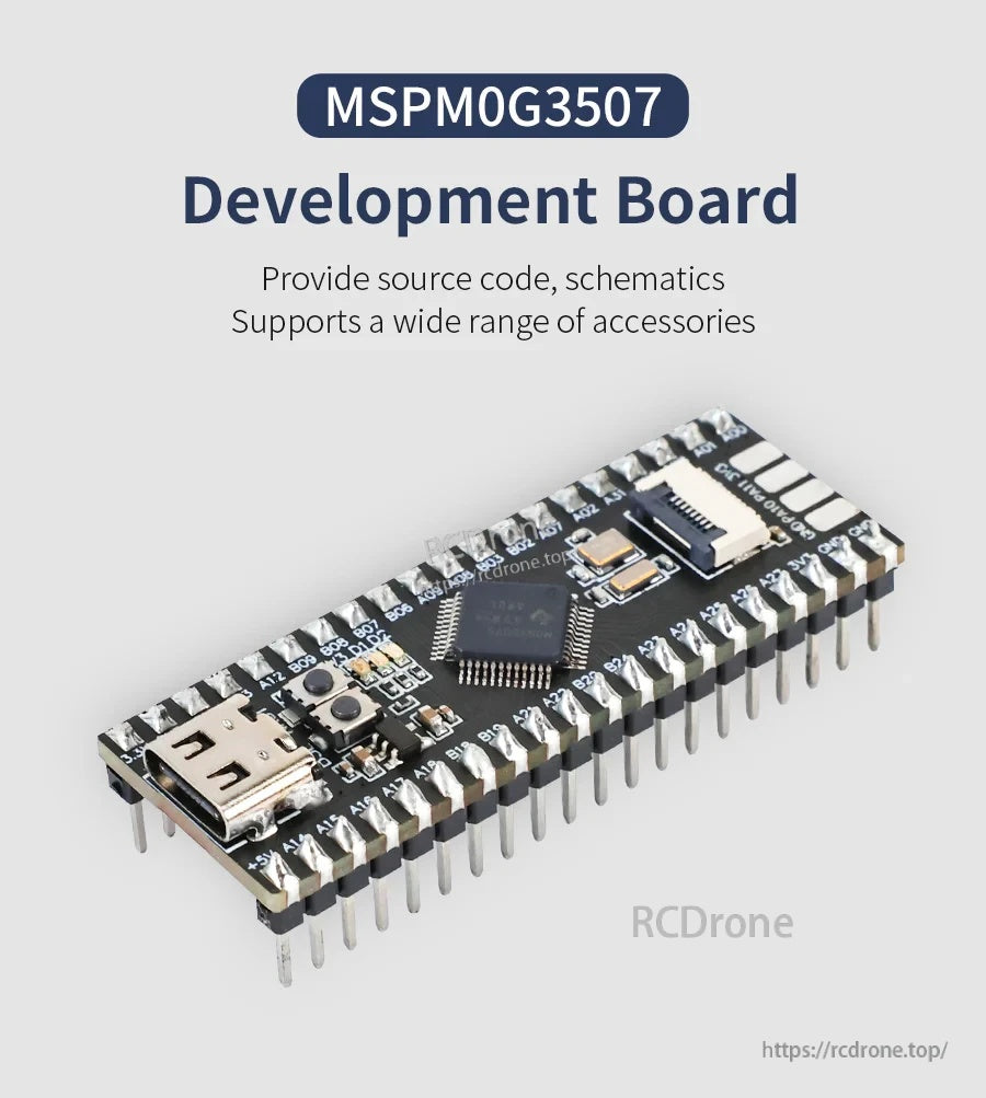
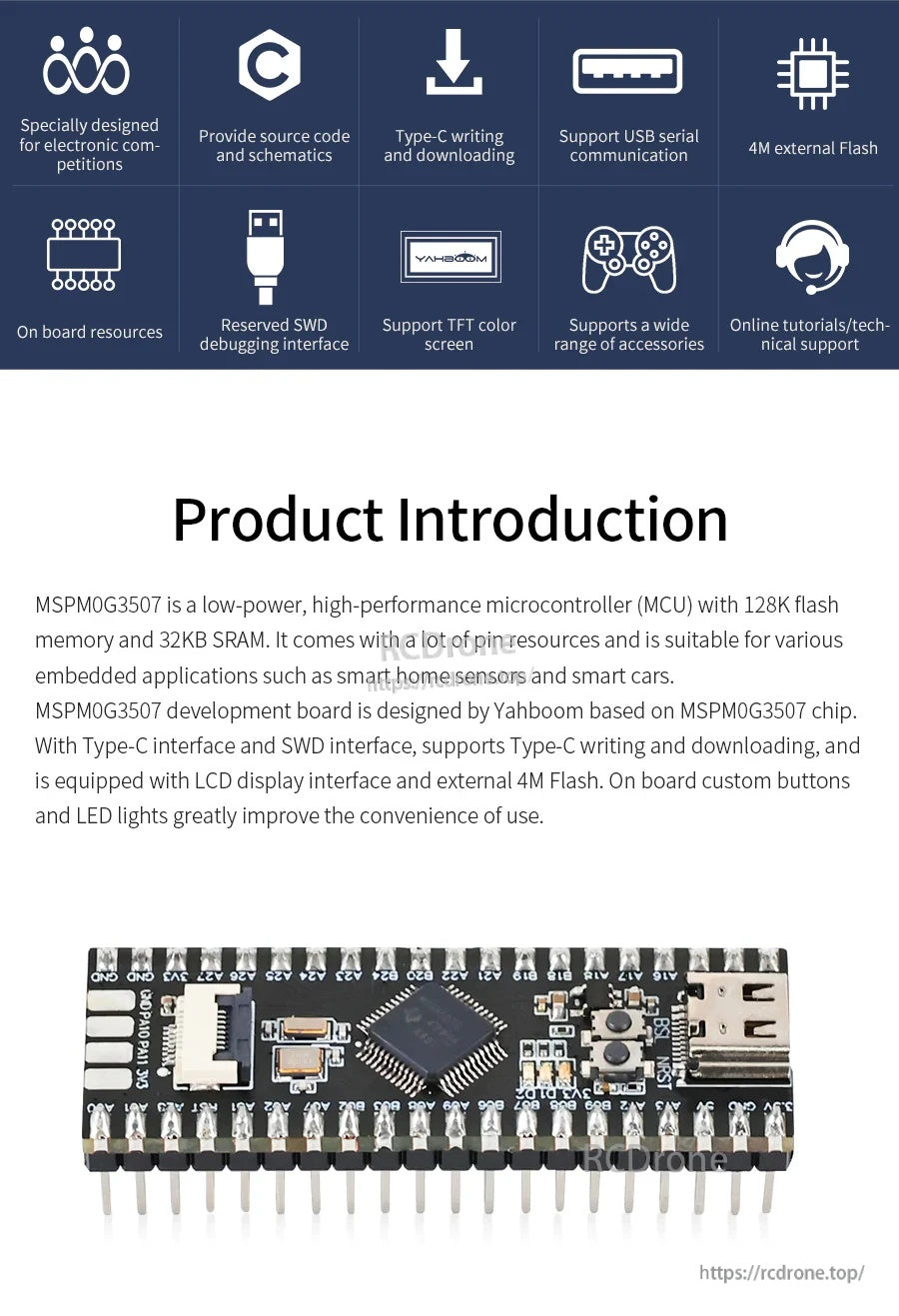
MSPM0G3507 মিনি ডেভেলপমেন্ট বোর্ড একটি এমবেডেড সিস্টেম ডেভেলপমেন্ট বোর্ড। এটি MSPM0G3507 MCU এর উপর ভিত্তি করে তৈরি এবং একটি কমপ্যাক্ট ৪০-পিন, ব্রেডবোর্ড-সামঞ্জস্যপূর্ণ লেআউটের মাধ্যমে প্রোগ্রাম ডাউনলোড, ডিবাগিং এবং সাধারণ পেরিফেরালগুলিতে সম্প্রসারণ সমর্থন করার জন্য ডিজাইন করা হয়েছে।
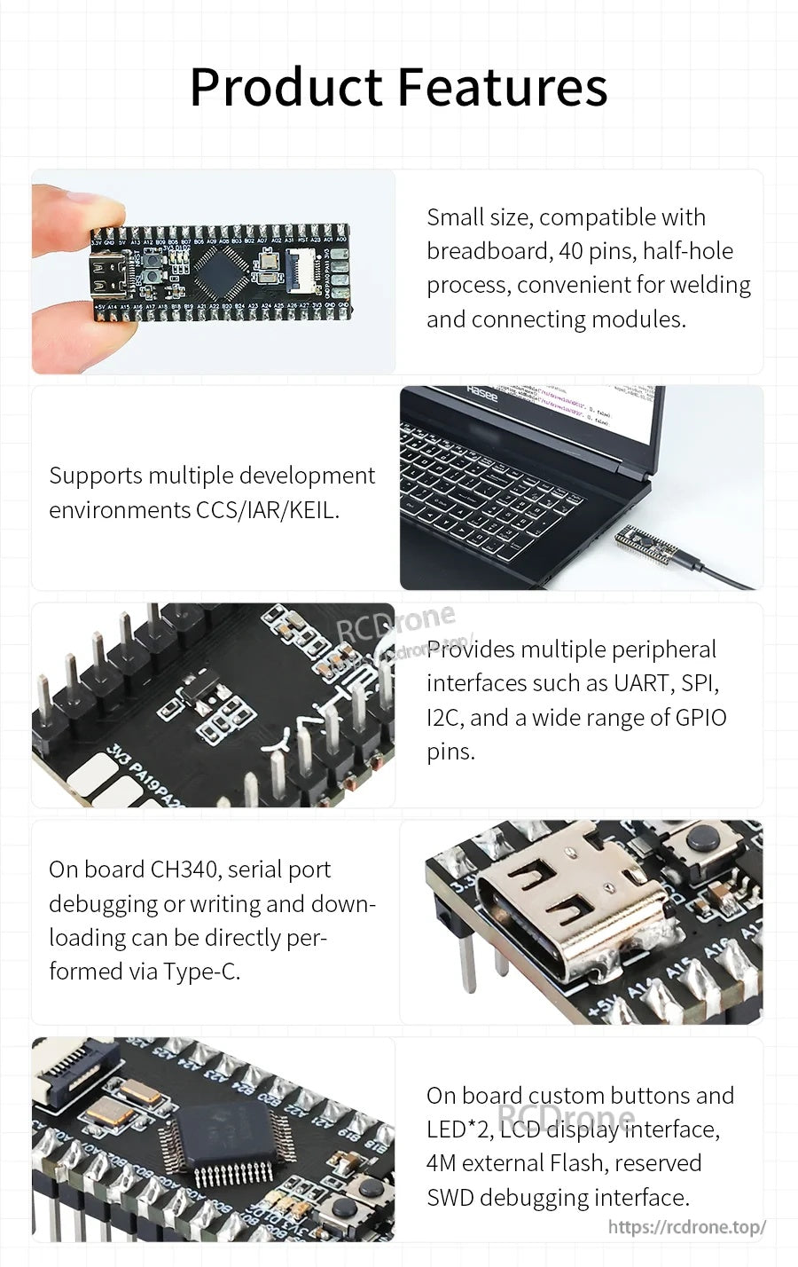
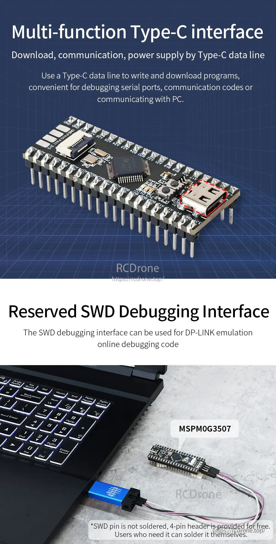
এটি অন-বোর্ড CH340 এর মাধ্যমে টাইপ-সি রাইটিং/ডাউনলোডিং এবং USB সিরিয়াল যোগাযোগ সমর্থন করে এবং দ্রুত পরীক্ষার এবং ইন্টারঅ্যাকশনের জন্য অন-বোর্ড বোতাম এবং LED অন্তর্ভুক্ত করে। DP-LINK এমুলেশন অনলাইন ডিবাগিংয়ের জন্য একটি সংরক্ষিত SWD ডিবাগিং ইন্টারফেস প্রদান করা হয়েছে (SWD পিনগুলি সোল্ডার করা হয়নি; প্রয়োজনে ব্যবহারকারীরা সেগুলি সোল্ডার করতে পারেন)।
পণ্য নির্বাচন বা বিক্রয়োত্তর সহায়তার জন্য যোগাযোগ করুন [email protected].
মূল বৈশিষ্ট্যসমূহ
- ইলেকট্রনিক প্রতিযোগিতার জন্য ডিজাইন করা হয়েছে; বিস্তৃত পরিসরের আনুষাঙ্গিক সমর্থন করে।
- সোর্স কোড এবং স্কিমেটিক প্রদান করে।
- টাইপ-সি রাইটিং এবং ডাউনলোডিং; টাইপ-সি ডেটা কেবলের মাধ্যমে ডাউনলোড/যোগাযোগ/বিদ্যুৎ।
- USB সিরিয়াল যোগাযোগের জন্য অন-বোর্ড CH340।
- সংরক্ষিত SWD ডিবাগিং ইন্টারফেস; SWD বা সিরিয়াল পোর্ট এক-কী ডাউনলোড সমর্থন করে।
- ৪০-পিন GPIO; ব্রেডবোর্ডের সাথে সামঞ্জস্যপূর্ণ ছোট আকার; ৪০ পিন; সহজ সোল্ডারিং/সংযোগের জন্য হাফ-হোল প্রক্রিয়া।
- অন-বোর্ড রিসোর্স: লাল পাওয়ার ইন্ডিকেটর, রিসেট বোতাম, কাস্টম বোতাম, এবং ২টি কাস্টম LED লাইট।
- অন-বোর্ড TFT রঙিন ডিসপ্লে ইন্টারফেস (8P FPC সংযোগকারী) 0.96-ইঞ্চি TFT রঙিন ডিসপ্লে সংযোগের জন্য।
- PCB প্রক্রিয়া নোট: সীসা-মুক্ত টিন-স্প্রে প্রক্রিয়া, হাফ-হোল প্রক্রিয়া, প্রান্তে কোনো বার নেই, উচ্চ-মানের SMD ক্রিস্টাল।
- একাধিক ডেভেলপমেন্ট পরিবেশ সমর্থন করে: CCS/IAR/KEIL।
বিশেষ উল্লেখ
| মডেল | MSPM0G3507 মিনি ডেভেলপমেন্ট বোর্ড |
| MCU | MSPM0G3507 |
| কোর | Cortex M0 |
| অভ্যন্তরীণ ফ্ল্যাশ | 128K |
| SRAM | 32K |
| বাহ্যিক ফ্ল্যাশ | 4M |
| প্রধান ফ্রিকোয়েন্সি ক্লক | 80Mhz |
| পিন প্যাকেজের সংখ্যা | 48 |
| পিন প্যাকেজ | LQFP48 |
| টাইমার | 7 |
| ADC | 2 x ADC (12 bit/17 channel) |
| DAC | 1 x DAC |
| ইন্টারফেস রিসোর্স | 2 x SPI, 4 x UART, 2 x I2C, 1 x CAN, 32 x I/O |
| USB-টু-সিরিয়াল | CH340 |
| প্রোগ্রাম ডাউনলোড | SWD বা সিরিয়াল পোর্ট এক-কী ডাউনলোড |
| ডিবাগ ইন্টারফেস | রিজার্ভড SWD ডিবাগিং ইন্টারফেস (DP-LINK এমুলেশন অনলাইন ডিবাগিং কোড) |
| বোতামগুলি | রিসেট বোতাম, কাস্টম বোতাম |
| এলইডি | লাল পাওয়ার সূচক, কাস্টম LED লাইট x2 |
| ডিসপ্লে সংযোগকারী | LCD ডিসপ্লে ইন্টারফেস; 8P FPC সংযোগকারী |
| পাওয়ার সাপ্লাই পদ্ধতি | টাইপ-C পাওয়ার সাপ্লাই; পিন পাওয়ার সাপ্লাই |
| ভোল্টেজ রেঞ্জ (ADC) | বাহ্যিক ভোল্টেজ: 1.62V - 3.6V; কোর ভোল্টেজ: 2.5V |
| বিদ্যুৎ খরচ | স্লিপ মোড: 2.76mA/80MHz; স্ট্যান্ডবাই মোড: 1.5uA; অপারেশন পাওয়ার খরচ: 8mA/80M |
| আকার | 18.89 x 51.12 mm |
| ওজন | 7g |
I/O রিসোর্স (I/O রিসোর্স ডিসপ্লে থেকে লিজেন্ড)
- সিরিয়াল পোর্ট পিন
- টাইমার পিন
- SPI পিন
- I2C পিন
- CAN পিন
- কম্পারেটর পিন
- অ্যানালগ ইনপুট পিন
- রেফারেন্স ভোল্টেজ
- DAC আউটপুট
- বিশেষ পিন
- চপার অ্যাম্প্লিফায়ার
- জেনারেল অ্যাম্প্লিফায়ার
- গ্রুপ A পোর্ট
- 3.3V পাওয়ার সাপ্লাই
- 5V পাওয়ার সাপ্লাই
- GND
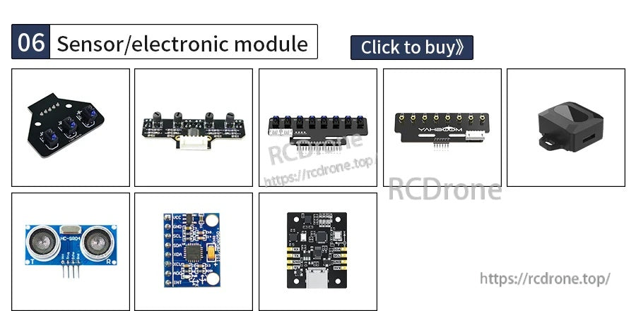
ঐচ্ছিক আনুষঙ্গিক (তথ্যসূত্র)
0.96-inch TFT LCD (via SPI, 8Pin connector) - Parameters
| আকার | 0.96 ইঞ্চি |
| উপাদান | এইচডি আইপিএস এলসিডি |
| রেজোলিউশন | 80(H)RGB x 160(V) |
| ড্রাইভার চিপ | ST7735S |
| যোগাযোগ ইন্টারফেস | SPI |
| ডিসপ্লে রঙ | পূর্ণ রঙ |
| ডিসপ্লে এলাকা | 10.8(H) x 21.7(V) মিমি |
| প্যানেল আকার | 13.5(H) x 27.95(V) x 1.5(D) মিমি |
| পিক্সেল পিচ | 0.135(H) x 0.1356(V) মিমি |
| সংযোগ পদ্ধতি | প্লাগ-ইন টাইপ 8Pin (0.5mmPitch প্লাগ-ইন টাইপ) |
| কাজের বর্তমান | 20ma |
| কাজের ভোল্টেজ | 3.3V |
| কাজের তাপমাত্রা | -20~70°C |
| ব্যাকলাইটের ধরন | সাইড-এন্ট্রি LED ব্যাকলাইট উৎস |
ঐচ্ছিক MSPM0 রোবট এক্সপ্যানশন বোর্ড - স্পেসিফিকেশন
| জন্য ডিজাইন করা হয়েছে | MSPM0G3507 ডেভেলপমেন্ট বোর্ড |
| মাত্রা | 100.45 x 64.18 x 14 mm |
| ওজন | 43g |
| পাওয়ার ইনপুট ইন্টারফেস | 5~12V পাওয়ার ইনপুট |
| পাওয়ার আউটপুট ইন্টারফেস | 5~12V (পাওয়ার ইনপুট ইন্টারফেসের মতো) |
| পাওয়ার ইনপুট ইন্টারফেস মডেল | KF301-2P স্পেসিং 5.08mm |
| পাওয়ার আউটপুট ইন্টারফেস মডেল | KF301-2P স্পেসিং 5.08mm |
| অনবোর্ড রিসোর্সেস | বাটন x4, বাজার |
| পিন হেডার ইন্টারফেস | 40পিন GPIO পিন হেডার, সার্ভো ইন্টারফেস x2 |
| সিরিয়াল পোর্ট ইন্টারফেস মডেল | PH2.0-4P x3, 2.54mm হেডার x2 |
| IIC ইন্টারফেস মডেল | PH2.0-4P x3, 2.54mm হেডার x2 |
| CCD মডিউল ইন্টারফেস মডেল | XH2.54-5P |
| 4-চ্যানেল ট্র্যাকিং মডিউল ইন্টারফেস মডেল | XH2.54-6P |
| 3-চ্যানেল ট্র্যাকিং মডিউল ইন্টারফেস মডেল | XH2.54-5P |
| ইলেক্ট্রোম্যাগনেটিক লাইন প্যাট্রোল মডিউল ইন্টারফেস মডেল | XH2.54-6P x2 |
| সমর্থিত সিরিয়াল পোর্ট ডিভাইস | 4-চ্যানেল এনকোডার মোটর ড্রাইভার মডিউল, K210 ভিশন মডিউল, 10-অ্যাক্সিস IMU ইনর্শিয়াল ন্যাভিগেশন, BT 5.0, ইত্যাদি। |
| সমর্থিত IIC ডিভাইস | ৮-চ্যানেল ট্র্যাকিং মডিউল, OLED ডিসপ্লে, ইত্যাদি। |
ঐচ্ছিক MSPM0 রোবট সম্প্রসারণ বোর্ড - লেবেলযুক্ত ইন্টারফেস (১-১৮)
- ১) ৪-চ্যানেল এনকোডার মোটর ড্রাইভ ইন্টারফেস
- ২) সিরিয়াল পোর্ট ইন্টারফেস
- ৩) K210 ভিশন মডিউল ইন্টারফেস
- ৪) IIC ইন্টারফেস
- ৫) ৮-চ্যানেল ট্র্যাকিং মডিউল ইন্টারফেস
- ৬) সার্ভো ইন্টারফেস
- ৭) কাস্টমাইজড বোতাম
- ৮) সিরিয়াল পোর্ট ইন্টারফেস
- ৯) IIC ইন্টারফেস
- ১০) সুইচ
- ১১) ৫-১২V পাওয়ার ইনপুট ইন্টারফেস
- ১২) পাওয়ার আউটপুট ইন্টারফেস
- ১৩) বাজার
- ১৪) ইলেক্ট্রোম্যাগনেটিক মডিউল ইন্টারফেস
- ১৫) ৪-চ্যানেল ট্র্যাকিং মডিউল ইন্টারফেস
- ১৬) ৩-চ্যানেল ট্র্যাকিং মডিউল ইন্টারফেস
- ১৭) CCD মডিউল ইন্টারফেস
- ১৮) 40PinGPIO পিন হেডার
ম্যানুয়াল / টিউটোরিয়াল
MSPM0G3507 ডেভেলপমেন্ট বোর্ড টিউটোরিয়াল
বিস্তারিত
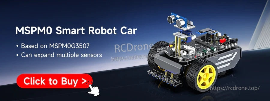
MSPM0G3507-ভিত্তিক কন্ট্রোলার দিয়ে MSPM0 রোবট এবং স্মার্ট-সেন্সর প্রকল্প তৈরি করুন।
একটি কমপ্যাক্ট ৪০-পিন বোর্ড লেআউট স্ট্যান্ডার্ড ব্রেডবোর্ডে ফিট করে, যখন টাইপ-সি অ্যাক্সেস সহজে প্রান্তে রাখে।
টাইপ-সি পাওয়ার এবং প্রোগ্রামিং পরিচালনা করে, CH340 USB-সিরিয়াল সমর্থন এবং ডিবাগিংয়ের জন্য সংরক্ষিত SWD প্যাড সহ।
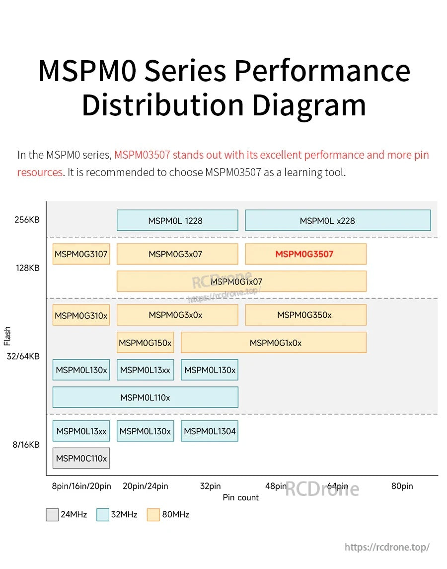
একটি দ্রুত পরিবার তুলনা মেমরি এবং প্যাকেজ আকার দ্বারা অন্যান্য MSPM0 বিকল্পগুলির মধ্যে MSPM0G3507 স্থাপন করতে সহায়তা করে।
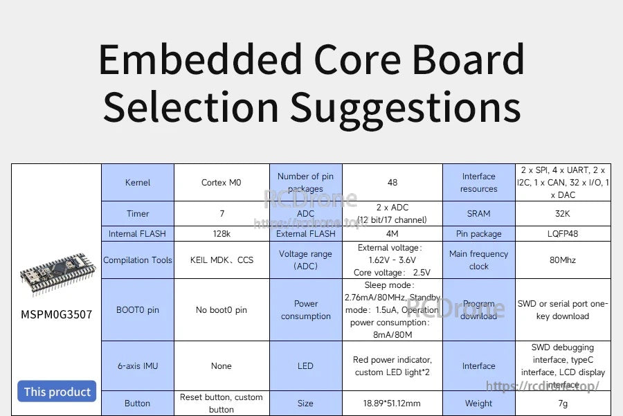
মূল স্পেসিফিকেশনগুলি শেখার, প্রোটোটাইপিং বা প্রতিযোগিতার প্রস্তুতির সময় দ্রুত বোর্ড নির্বাচন করার জন্য সংক্ষেপে দেওয়া হয়েছে।
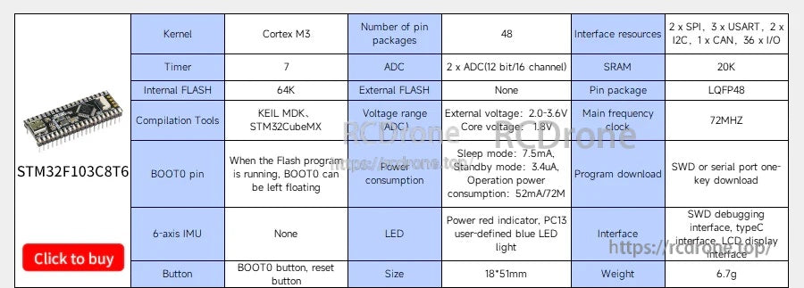
একটি রেফারেন্স তুলনা টেবিল অন্তর্ভুক্ত করা হয়েছে যাতে MSPM0 বিকল্পের পাশাপাশি সাধারণ বিকল্পগুলি মূল্যায়ন করতে সহায়তা করে।
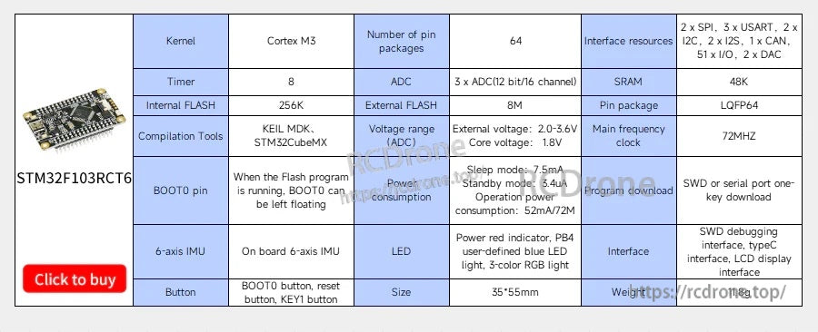
একটি দ্বিতীয় রেফারেন্স তুলনা টেবিল বিভিন্ন MCU শ্রেণীর জন্য পাশাপাশি নির্বাচন সমর্থন করে।
একাধিক উন্নয়ন পরিবেশ সমর্থিত, এবং অনবোর্ড বোতাম/এলইডি দ্রুত ব্রিং-আপ পরীক্ষাগুলি সহজ করে।
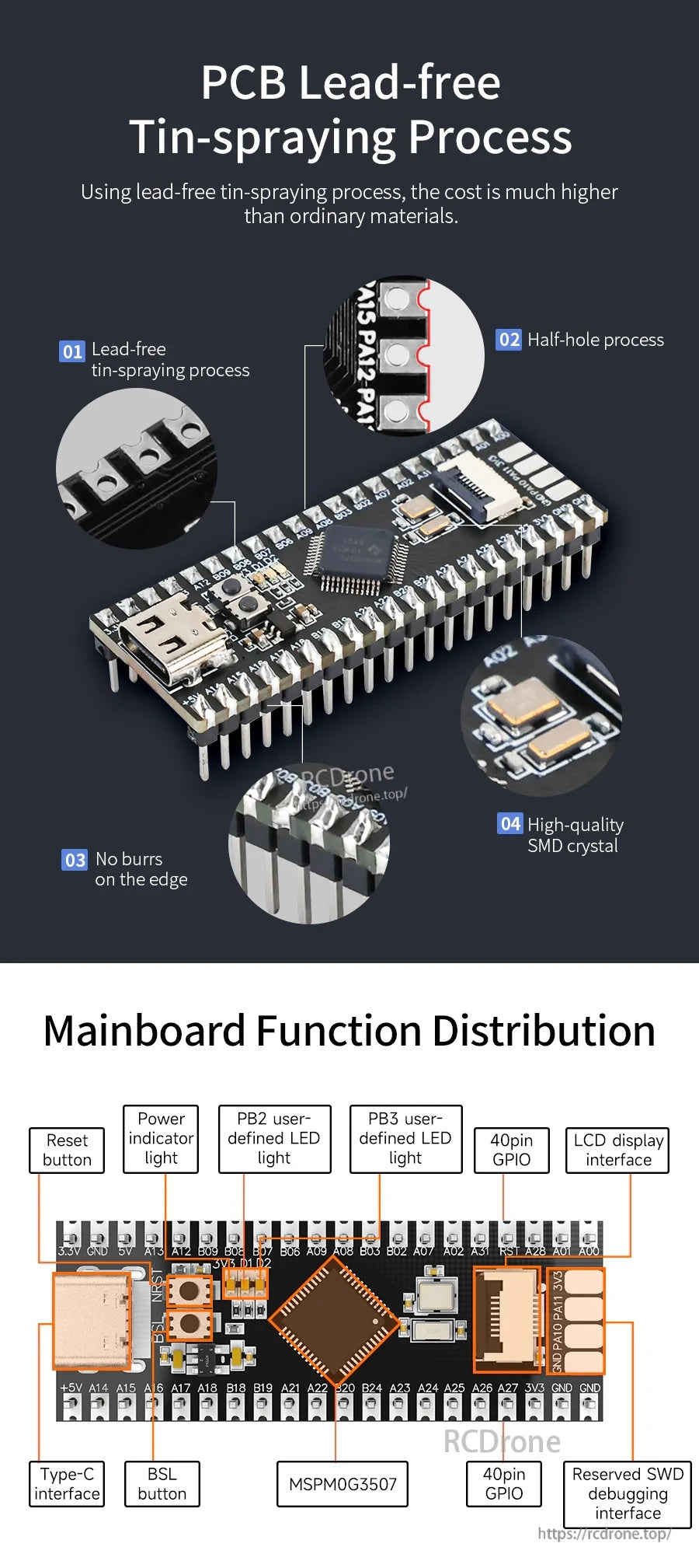
স্পষ্ট কলআউটগুলি প্রধান বোর্ডে টাইপ-সি পোর্ট, বোতাম, LED সূচক এবং সংরক্ষিত ইন্টারফেসগুলি চিহ্নিত করে।
ডাউনলোড এবং সিরিয়াল যোগাযোগের জন্য টাইপ-সি ব্যবহার করুন, তারপর গভীরতর ডিবাগিংয়ের প্রয়োজন হলে SWD পিন যোগ করুন।
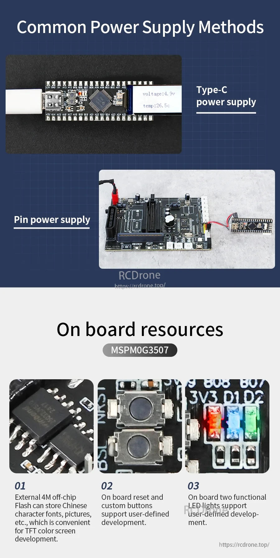
শক্তি টাইপ-সি বা হেডার পিন থেকে আসতে পারে, এবং অনবোর্ড রিসেট/ইউজার কন্ট্রোলগুলি পরীক্ষাকে সুবিধাজনক রাখে।
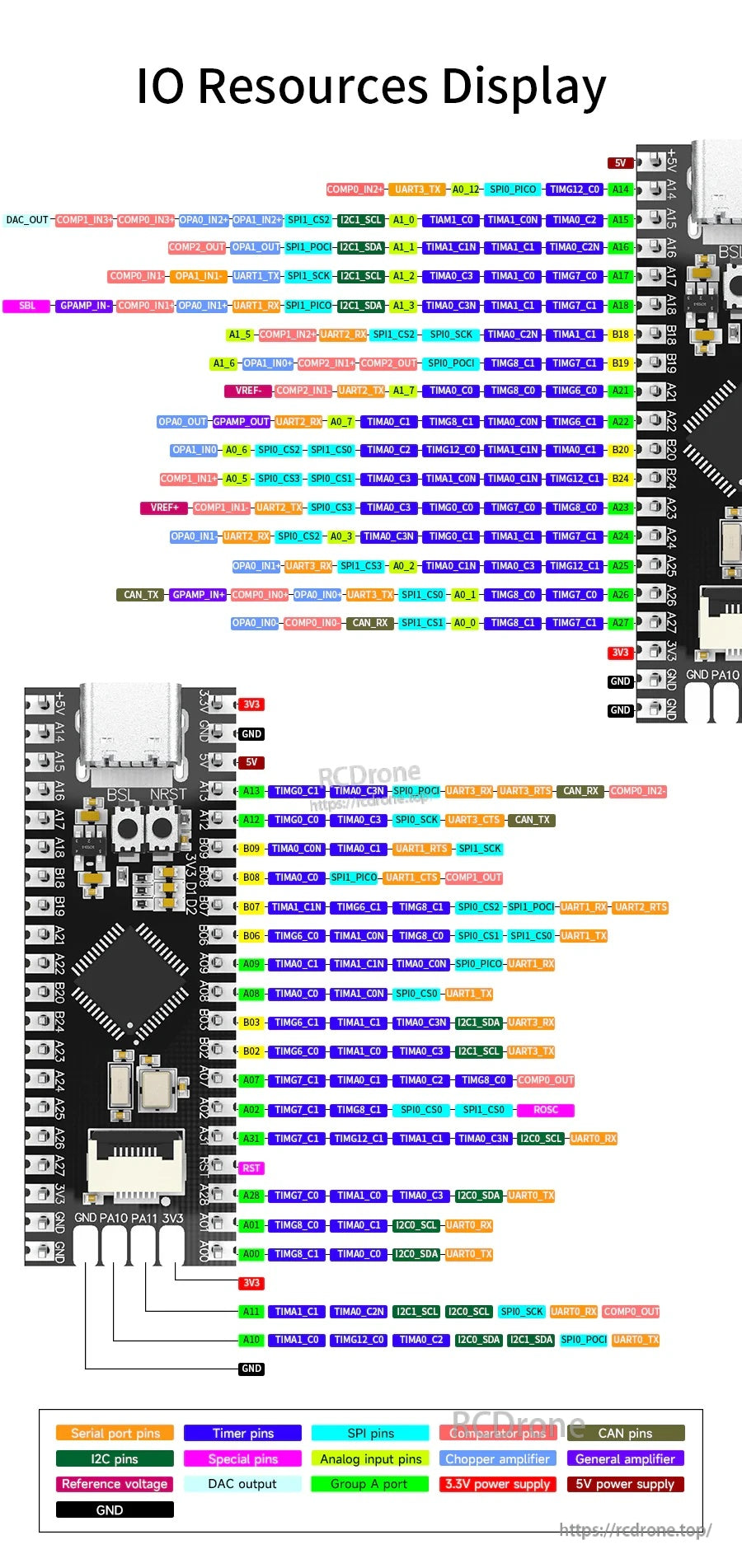
একটি পূর্ণ পিন ম্যাপ UART, SPI, I2C, টাইমার, ADC এবং অন্যান্য ফাংশন হেডারে রাউট করা সহজ করে তোলে।
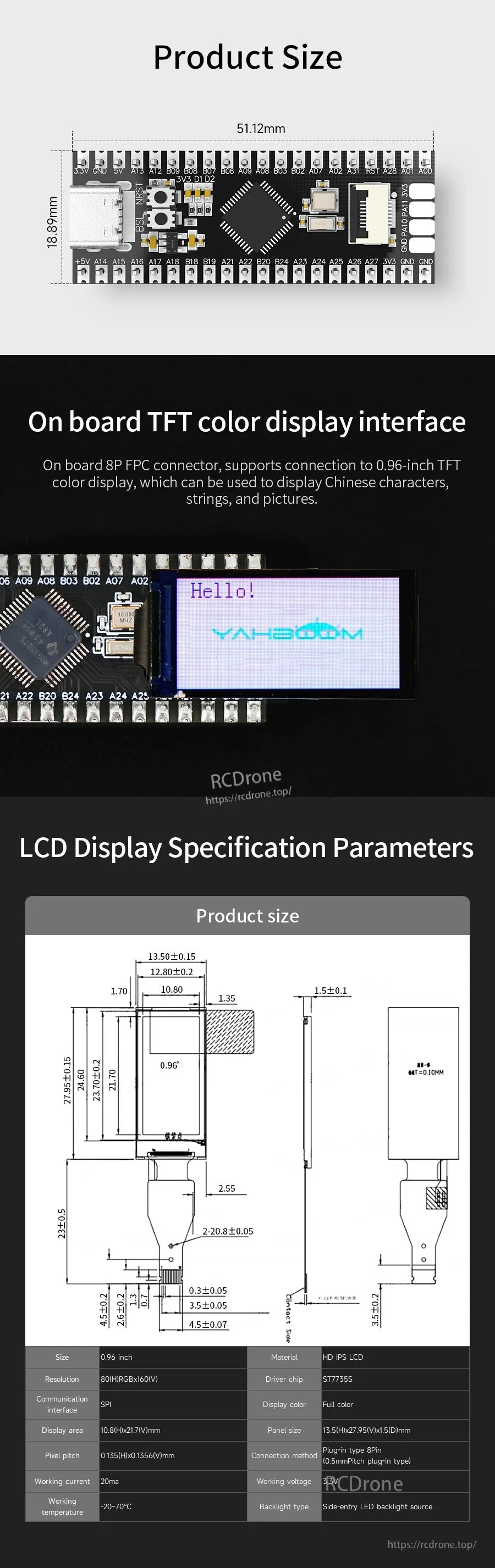
বোর্ডের মাত্রা এবং ৮-পিন FPC ডিসপ্লে সংযোগকারী যান্ত্রিক এবং কেবল পরিকল্পনার জন্য প্রদান করা হয়েছে।
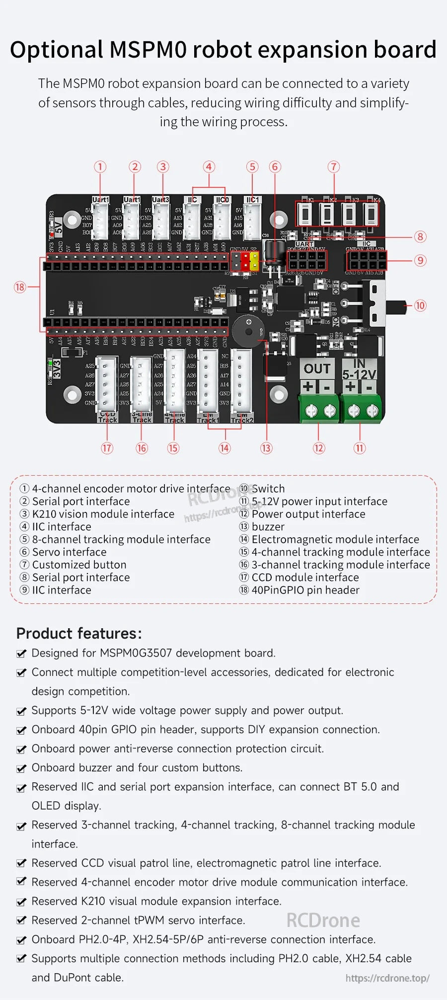
একটি ঐচ্ছিক সম্প্রসারণ বোর্ড সাধারণ সেন্সর এবং মোটর পোর্ট একত্রিত করে রোবট গাড়ির জন্য তারের সহজ করতে পারে।
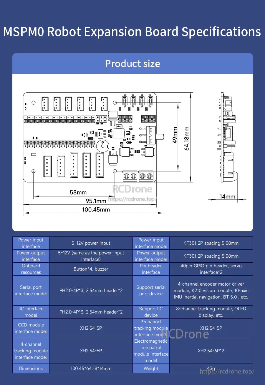
যান্ত্রিক অঙ্কন এবং সংযোগকারী স্পেসিং সম্প্রসারণ বোর্ডকে একটি চ্যাসিসে সংহত করার আগে ফিট নিশ্চিত করতে সহায়তা করে।
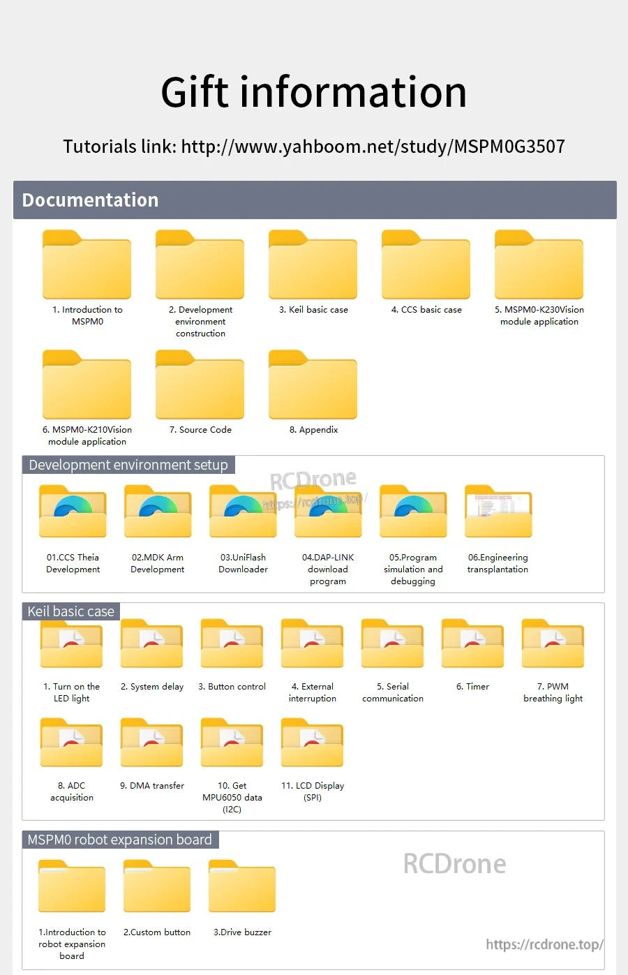
টিউটোরিয়াল লিঙ্ক এবং কাঠামোবদ্ধ ডাউনলোড আপনাকে উদাহরণ, সরঞ্জাম এবং সেটআপ গাইড সহ দ্রুত শুরু করতে সহায়তা করে।
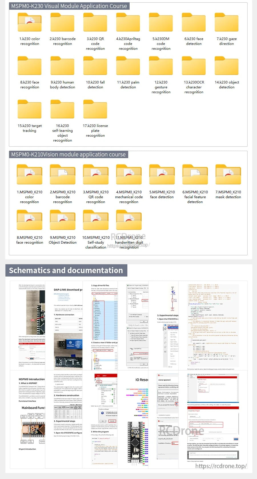
তথ্যসূত্রের উপকরণগুলির মধ্যে কোর্স মডিউলগুলি প্লাস স্কিম্যাটিক্স এবং গভীরতর উন্নয়ন কাজের জন্য ডকুমেন্টেশন অন্তর্ভুক্ত রয়েছে।
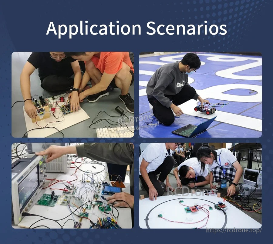
সাধারণ ব্যবহার ক্ষেত্রে অন্তর্ভুক্ত রয়েছে শ্রেণীকক্ষের ল্যাব, রোবোটিক্স প্রতিযোগিতা এবং টেস্ট বেঞ্চে দ্রুত প্রোটোটাইপিং।
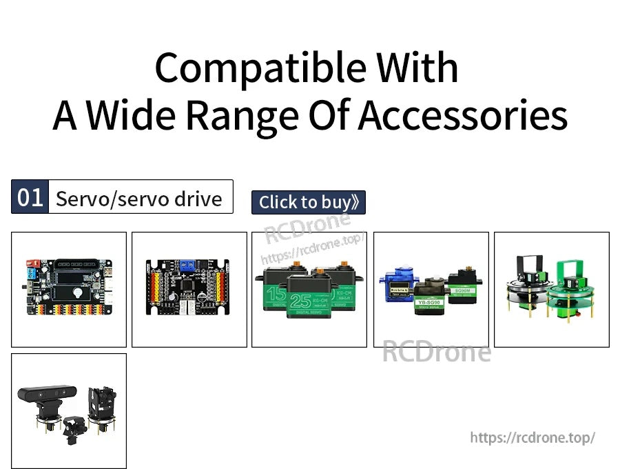
উন্নয়ন বোর্ডটি সাধারণ সার্ভো এবং সার্ভো-ড্রাইভ আনুষাঙ্গিকগুলির সাথে কাজ করার জন্য ডিজাইন করা হয়েছে সহজ সম্প্রসারণের জন্য।
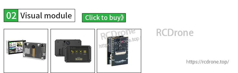
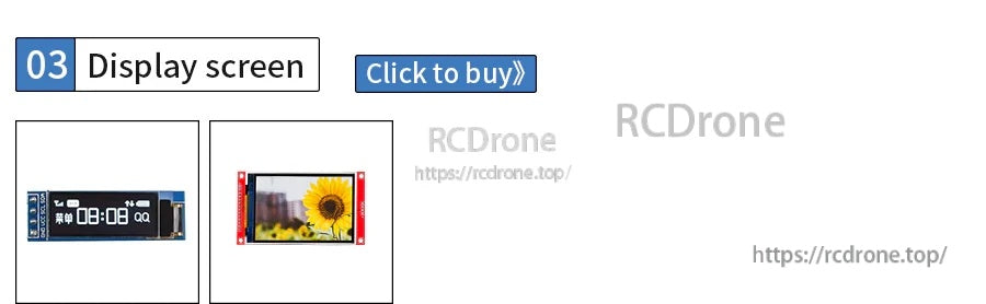
ঐচ্ছিক OLED এবং রঙ TFT ডিসপ্লে মডিউলগুলি একটি কমপ্যাক্ট উপায় প্রদান করে অন-ডিভাইস স্ট্যাটাস এবং সহজ গ্রাফিক্স যোগ করার জন্য।
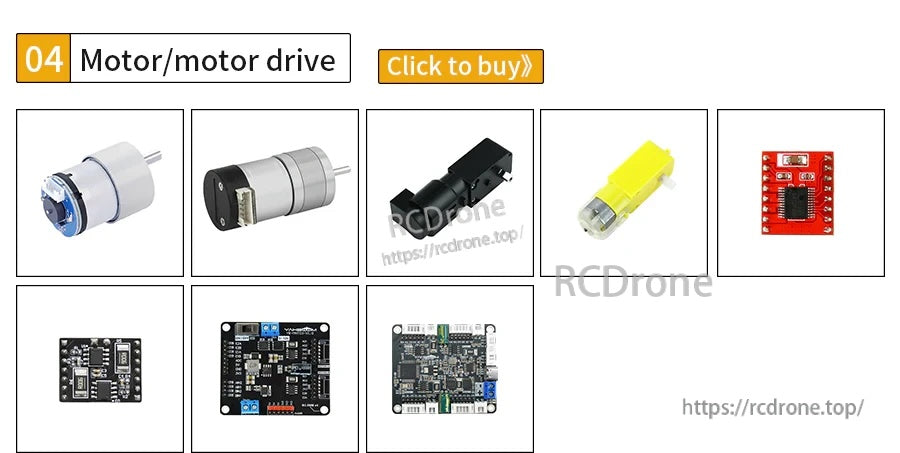
মোটর এবং মোটর ড্রাইভার বিকল্পগুলির মধ্যে রয়েছে ছোট ডিসি মোটর, ওয়্যারিং সংযোগকারী এবং ড্রাইভ সেটআপের জন্য কমপ্যাক্ট কন্ট্রোল বোর্ড।

গাড়ির চেসিস কিটটিতে একটি কমপ্যাক্ট চাকা বেস অন্তর্ভুক্ত রয়েছে একটি শীর্ষ মাউন্টিং প্লেট সহ আপনার নিজস্ব কন্ট্রোলার এবং ইলেকট্রনিক্স যোগ করার জন্য।
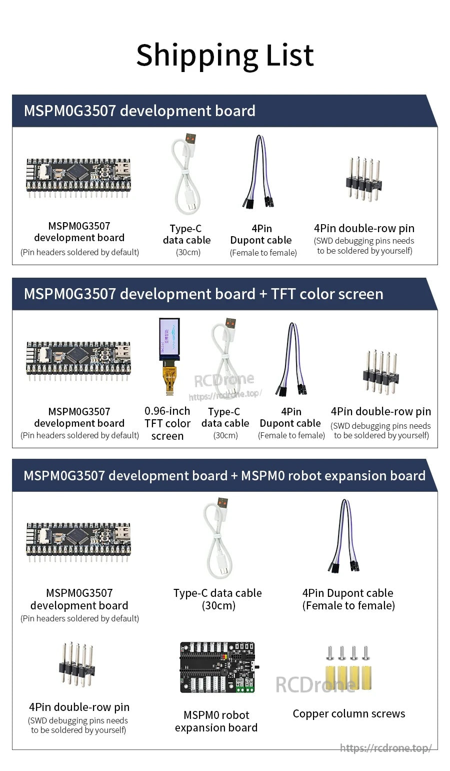
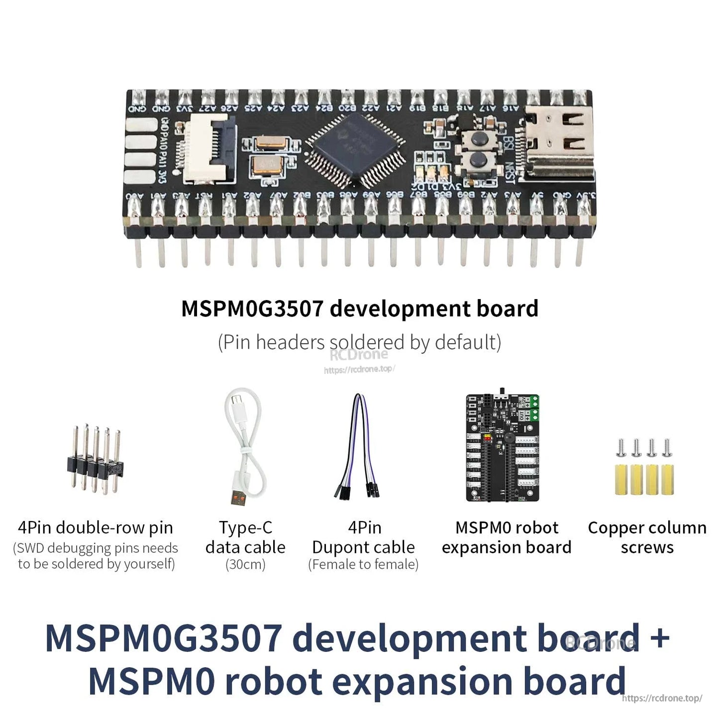
প্যাকেজটিতে একটি USB-C ডেটা কেবল, 4-পিন ডুপন্ট লিড এবং হেডার পিন সহ MSPM0G3507 ডেভেলপমেন্ট বোর্ড অন্তর্ভুক্ত রয়েছে, ঐচ্ছিক কিটগুলি একটি 0.96-ইঞ্চি TFT স্ক্রীন বা একটি MSPM0 রোবট এক্সপ্যানশন বোর্ড প্লাস স্ট্যান্ডঅফ এবং একটি 4
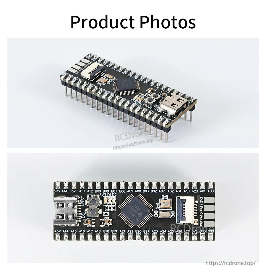
USB-C সংযোগকারী এবং স্পষ্টভাবে লেবেল করা 40-পিন GPIO বিন্যাস MSPM0G3507 বোর্ডে তারের এবং প্রোটোটাইপিং সহজ করতে সহায়তা করে।
Related Collections