RadioMaster MT12 Gyro-Steuermodul 2-Achsen Handgestensteuerung für MT12 Erweiterungssteckplatz (EdgeTX-Mischung)
RadioMaster MT12 Gyro-Steuermodul 2-Achsen Handgestensteuerung für MT12 Erweiterungssteckplatz (EdgeTX-Mischung)
RadioMaster
Verfügbarkeit für Abholungen konnte nicht geladen werden
Übersicht
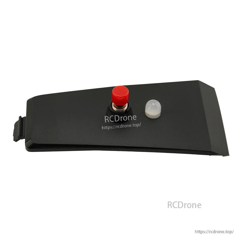
Das RadioMaster MT12 Gyro Control Module ist ein zweiachsiges Gyroskop, das die Steuerung von zwei Kanälen mittels Handgesten ermöglicht. Es integriert sich in den MT12-Erweiterungssteckplatz und speist Handbewegungen durch das fortschrittliche Mischen und die Programmierbarkeit von EdgeTX in den Steuerstrom ein, geeignet für Anwendungen wie Pan/Tilt-Gimbal-Steuerung, RC-Modell-Turmsteuerung, Hinterradlenkung und mehr.
Für Produktwahl oder Hilfe bei der Einrichtung kontaktieren Sie [email protected] or besuchen Sie https://rcdrone.top/.
Hauptmerkmale
- Zweiachsige Gyro-Gestensteuerung zur Steuerung von zwei Kanälen
- Für die Installation im MT12-Erweiterungssteckplatz konzipiert
- Funktioniert mit EdgeTX-Mischung und Modellprogrammierbarkeit
- Neutrale Kalibrierung des Sensors auf dem Modul über Taste (Status-LED-Anzeige)
Technische Daten
| Stromversorgung | DC 3.3V |
| Gewicht | 8,3 g |
| Abmessungen | 65,0 x 33.0 mm |
| X-Achsen-Winkelbereich | 90° (-45° bis 45°) |
| Y-Achsen-Winkelbereich | 90° (-45° bis 45°) |
Installation
- Entfernen Sie die Batterie von der Unterseite des MT12.
- Entfernen Sie die obere Abdeckung des MT12, indem Sie sie vom Griff wegdrücken.
- Installieren Sie das Gyro-Modul oben auf der Funkbasis.
- Stecken Sie das Kabel in den 5-poligen Anschluss im Batteriefach.
So verwenden Sie
MT12 Radioeinstellungen
- Hardware-Menü: Drücken Sie SYS und verwenden Sie PAGE , um zu HARDWARE. Set S3 und S4 unter Pots auf Achse X und Achse Y.
- Kalibrierung im MT12: Drücken Sie SYS und verwenden Sie PAGE, um zu HARDWARE, zu navigieren, und geben Sie dann [Kalibrierung]. ein. Bei SET AXIS MIDPOINT, legen Sie das MT12-Niveau auf einen Tisch und drücken Sie das Scrollrad, um den Neutralpunkt zu kalibrieren. Bei MOVE AXIS/POTS, heben Sie das MT12 an und bewegen Sie es vor/zurück und seitwärts mit Winkeln größer als 45 Grad.
- Eingabemenü: Drücken Sie MDL und verwenden Sie PAGE, um zu INPUT. zu navigieren. Binden Sie den Gyro-Ausgang an zwei Eingabekanäle (Beispiel: Achse X (S3) zu I09 und Achse Y (S4) zu I10). Um die Quelle für einen Eingang festzulegen, öffnen Sie das Bearbeiten-Menü des Eingangs, wählen Sie Quelle, aus, drücken Sie das Scrollrad und neigen Sie das MT12, damit die Quelle erkannt wird.
- Mischermenü: Drücken Sie MDL und verwenden Sie PAGE, um zu MIXER. zu navigieren.Binden Sie die Gyro-Eingänge an die Empfänger-Ausgangskanäle (Beispiel: Achse X an Kanal 3 und Achse Y an Kanal 4). Öffnen Sie für einen Kanal das Bearbeiten-Menü, wählen Sie Quelle, drücken Sie das Scrollrad und neigen Sie das MT12, damit der Eingang erkannt wird.
Gyro-Sensor-Kalibrierung (Am Modul)
- Drücken und halten Sie die rote Taste 2 Sekunden lang, um den Neutralpunkt des Sensors zu kalibrieren.
- Während der Kalibrierung blinkt das rote Licht.
- Ein stetiges grünes Licht zeigt den normalen Betrieb an.
Was ist enthalten
- 1 x MT12 Gyro-Steuermodul
- 1 x 5-poliges JST-Kabel (am Modul installiert)
Details

Verwenden Sie Handgesten, um zwei Kanäle zu steuern – ideal für Schwenk-/Neigegimbals, RC-Türme oder Hinterradlenkung.
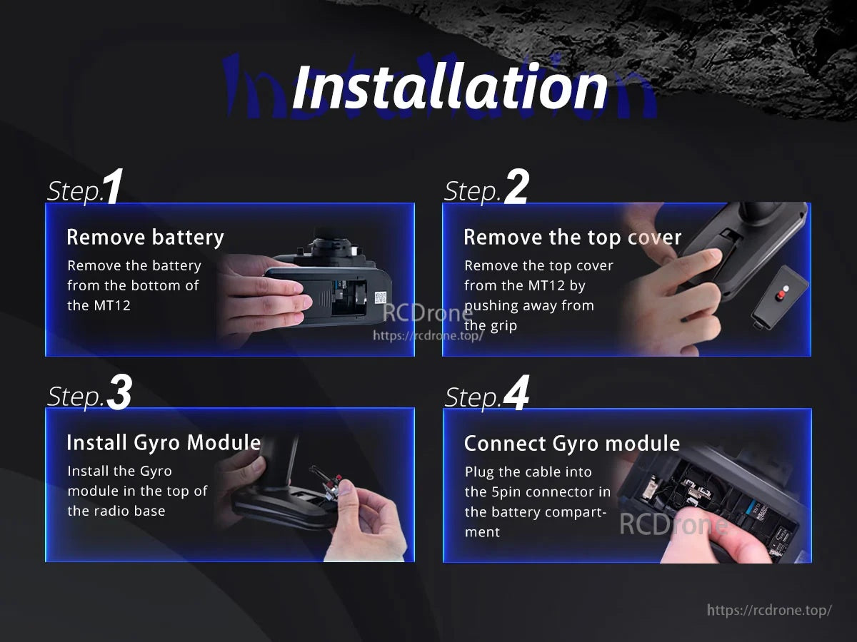
Die Installation erfolgt in vier schnellen Schritten: Entfernen Sie die Batterie und die obere Abdeckung, setzen Sie das Modul in den Erweiterungssteckplatz ein und schließen Sie dann den 5-poligen Stecker an.
Related Collections