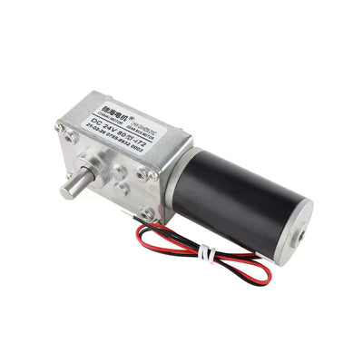
CHIHAI MOTOR CHS-GM20-20BY Geared Stepper Motor, 20mm
CHIHAI MOTOR CHS-GM20-20BY Geared Stepper Motor, 20mm
CHIHAI MOTOR
पिकअप उपलब्धता लोड नहीं की जा सकी


Overview
The CHIHAI MOTOR CHS-GM20-20BY is a 20 mm geared stepper with a two-phase four-wire motor and metal reduction gears. Choose one of ten ratio options and a motor-only, bracket or reciprocating-driver package. This compact electric motor provides ratio-dependent output steps, speed and torque for positioning mechanisms.
Features
- Metal reduction gears in a compact cylindrical housing.
- 18° input motor step with finer output increments through the gearbox.
- 4 mm D-shaped output shaft with a 3.5 mm flat reference.
- Four-wire PHR-4 connection and accessible PCB wiring.
- Optional lightweight anodized mounting bracket and button-operated reciprocating driver.
Specifications
| Specification | Value |
|---|---|
| Brand / model | CHIHAI MOTOR / CHS-GM20-20BY |
| Motor / transmission | Two-phase four-wire bipolar stepper; metal reduction gears |
| Supply range / test reference | 5–12V DC operating reference; electrical tests at 12V DC with L6219 driver reference |
| Diameter / motor section | 20 mm /18.6 mm drawing reference |
| Gearbox length L | 16,17.5,19 or20.5 mm, depending on ratio; drawing tolerance ±0.3 mm |
| Motor input step | 18° per step |
| Phase resistance / inductance | 20 Ω ±7% /11 mH per phase |
| Phase current / excitation | 600 mA per phase at 12V reference /two-phase excitation |
| Input pull-out torque | >32 gf·cm at 500 pulses/s |
| Input holding torque | >60 gf·cm at 0 pulses/s |
| Input response / starting frequency | >1200 pulses/s response; >900 pulses/s starting |
| Practical pulse-rate guide | 300–1000 pulses/s; start around 300 pulses/s, stable-speed reference around 700 pulses/s |
| Winding insulation / dielectric test | Class E coils /100V AC for one second |
| Insulation resistance | 100 MΩ, tested at 500V DC |
| Operating temperature reference | 0 to+55°C |
| Motor weight | Approximately47 g; varies with reduction ratio |
| Output shaft diameter / D-flat | 4 mm, +0/−0.03 mm /3.5 mm, +0/−0.1 mm |
| Shaft projection / flat length | 10.5 ±0.5 mm drawing reference (10 mm nominal in product table) /7 mm |
| Front mounting | Two ISO M2.5 ×2 tapped holes;15 mm spacing |
| Other drawing references | 7 mm front register diameter;3 mm front offset;1 mm rear offset;6 mm rear shaft/bearing reference |
| Connector / wire length | PHR-4 /140 ±5 mm |
| Pin order / coil pairs | Pin1 yellow and pin2 red: phase A; pin3 black and pin4 blue: phase B |
| Gearbox maximum instantaneous load | 6.0 kgf·cm; do not exceed, and do not treat as continuous torque rating |
Ratio Selection and Performance
Three selectors use rounded nominal ratio names: 12 corresponds to 12.5:1, 31 to 31.25:1 and 62 to 62.5:1. The remaining selectable nominal labels are 25,50,78,100,125,195 and 250. The selector includes these nominal-to-precise mappings.
The following 12V table uses 700 input pulses/s. Additional ratios 156, 312.5,390 and 488 are series references and are not current selectable configurations. L is the gearbox-length reference. No-load speed, holding torque and pull-out torque are separate operating conditions.
| Precise ratio | Selectable nominal / scope | L (mm) | Output step (°) | No-load rpm at 700 pulses/s | Holding torque (kgf·cm) | Pull-out torque (kgf·cm) |
|---|---|---|---|---|---|---|
| 12.5:1 | 12 | 16 | 1.44 | 168 | ≥0.5 | ≥0.3 |
| 25:1 | 25 | 16 | 0.72 | 84 | ≥1.2 | ≥0.6 |
| 31.25:1 | 31 | 16 | 0.576 | 67 | ≥1.5 | ≥0.75 |
| 50:1 | 50 | 17.5 | 0.36 | 42 | ≥2.5 | ≥1.2 |
| 62.5:1 | 62 | 17.5 | 0.288 | 33 | ≥3.0 | ≥1.5 |
| 78:1 | 78 | 17.5 | 0.23 | 27 | ≥3.8 | ≥1.7 |
| 100:1 | 100 | 19 | 0.18 | 21 | ≥5.0 | ≥2.50 |
| 125:1 | 125 | 19 | 0.144 | 17 | Maximum 6.0 | ≥3.5 |
| 156:1 | Series reference only | 19 | 0.115 | 13 | Maximum 6.0 | ≥4.5 |
| 195:1 | 195 | 19 | 0.092 | 10 | Maximum 6.0 | ≥6.0 |
| 250:1 | 250 | 20.5 | 0.072 | 8 | Maximum 6.0 | Maximum 6.0 |
| 312.5:1 | Series reference only | 20.5 | 0.0576 | 6 | Maximum 6.0 | Maximum 6.0 |
| 390:1 | Series reference only | 20.5 | 0.0462 | 5 | Maximum 6.0 | Maximum 6.0 |
| 488:1 | Series reference only | 20.5 | 0.037 | 4 | Maximum 6.0 | Maximum 6.0 |
The cells marked Maximum give permissible limits, not guaranteed minimum torque. The gearbox's maximum instantaneous load is 6.0 kgf·cm; exceeding it can damage the gearbox and motor. It does not establish a continuous-duty rating.
Output speed in rpm = output step angle in degrees ×input pulse rate per second ×60 ÷360. There are 60 seconds per minute and 360 degrees per revolution. Speed depends on pulse rate and load; begin at a suitable starting frequency rather than assuming the highest no-load speed is available under load.
Wiring and Control
Use a compatible two-phase bipolar stepper driver. Connector pin order is 1 yellow,2 red,3 black,4 blue. Yellow/red form phase A and black/blue form phase B. Identify each coil pair and confirm direction with the actual driver before integrating the mechanism. The drawing shows the excitation sequence viewed from the flange side.
The motor requires a sequenced stepper drive rather than a direct two-wire DC connection. The recommended 300-pulse/s starting point and roughly 700-pulse/s stable-speed reference are application guides; the separate input-motor frequency specifications are test references. Actual starting and load capability depend on the driver, ratio, supply and mechanism.
The reciprocating-driver packages include the displayed button-operated board. Check its actual power and control terminal markings before connection; the motor's supply range does not establish all controller input limits or external signal compatibility.
Mechanical Installation
Select the ratio before designing the mounting envelope: gearbox length changes from 16 to 20.5 mm across the reference family. Check the shaft projection, D-flat, tapped mounting holes and wire clearance against the mechanism. Avoid forcing the shaft, stalling or applying an impact load.
| Optional mounting bracket | Specification / scope |
|---|---|
| Construction / mass | Anodized aluminum alloy;3 mm thick; approximately 6.5 g |
| Overall drawing references | 31 mm high ×23 mm base depth;16 mm front flat width |
| Motor face hole pattern | 17 mm horizontal and 15 mm vertical references;18.5 mm lower offset;7.1 mm center aperture;two 3.1 mm hole references |
| Base attachment | Two M5 threaded holes;23 ×16 mm base reference |
| Base hole offsets | 5 mm from first edge,10 mm hole spacing,8 mm to opposite edge;8 mm transverse offset |
| Mounting example scope | The illustrated CHR-GM20/25-style DC motor is a bracket-fit example; it is not a second included motor |
Applications
For compatible small positioning mechanisms, hobby robotics, model equipment and automation assemblies when the required resolution, torque, pulse drive and mechanical dimensions match the selected configuration.
What's Included
| Selected package | Contents |
|---|---|
| Motor Only | 1 × selected geared stepper motor |
| Motor + Mounting Bracket | 1 × motor and 1 × blue mounting bracket |
| Motor + Reciprocating Driver | 1 × motor and 1 × button-operated reciprocating driver |
| Motor + Bracket + Reciprocating Driver | 1 × motor,1 × bracket and 1 × reciprocating driver |
Each configuration includes one motor at the chosen ratio. A bracket and driver are included only when named in the package. A power supply, host controller and the DC motor shown in the bracket mounting example are not included.
FAQ
Why does the 12 ratio option show 12.5:1?
12 is the nominal selector label; its precise performance-table ratio is 12.5:1. The same distinction applies to 31/31.25 and 62/62.5.
Are all ratios the same length?
No. The gearbox-length reference varies with ratio. Check the L column and complete dimensional drawing before mounting.
Can this motor connect directly to a DC supply?
It needs a compatible two-phase bipolar stepper driver to sequence the coils. Choose a driver package if one is required.
Does 6 kgf·cm mean the motor can run continuously at that torque?
No. It is a maximum instantaneous gearbox-load limit. The table also distinguishes minimum test values from maximum permissible limits.
Does the bracket picture include another motor?
No. The DC motor in the bracket drawing is a mounting example; each current package contains one selected geared stepper motor.
Visual Details