CHIHAI CHS-GM25-25BY 25mm Geared Stepper Motor with Driver Options
CHIHAI CHS-GM25-25BY 25mm Geared Stepper Motor with Driver Options
CHIHAI MOTOR
पिकअप उपलब्धता लोड नहीं की जा सकी


Overview
The CHIHAI MOTOR CHS-GM25-25BY is a 25 mm geared stepper motor with two-phase, four-wire bipolar operation, a metal reduction gearbox and a 4 mm D-shaped shaft. Choose the reduction ratio and a motor-only or driver, mounting-bracket and power-supply package for compact positioning mechanisms.
Features
- Permanent-magnet stepper design with reversible rotation and discrete position control.
- Metal reduction gears and a protected wiring PCB.
- Ten selectable nominal reduction ratios from 4:1 to 100:1.
- Optional push-button driver board, enclosed driver, bracket and power supply as named in the package.
Specifications
| Item | Specification |
|---|---|
| Model | CHS-GM25-25BY / GM25GA-25BY |
| Motor | Permanent-magnet, bipolar, 2-phase 4-wire stepper with metal reduction gears |
| Rated motor reference | 12V DC with L6219 driver; 300 mA per phase |
| Phase resistance | 10 ohm ±7% |
| Phase inductance | 7.5 mH per phase |
| Input step angle | 15 degrees per step |
| Excitation | 2-phase excitation; bipolar drive |
| Connector | PHR-4, 2.0 mm pitch, white 4-pin |
| Lead wire | UL1571 AWG28; 150 ±10 mm |
| Motor diameter | 25 mm |
| Output shaft | 4 mm D-shaft; flat dimension 3.5 mm; projection 12 mm; D-flat length 8 mm |
| Front boss | 7 mm diameter |
| Motor rear length | 14.8 mm; gearbox L depends on ratio |
| Mounting | 2 x M3 tapped holes, 17.0 mm spacing; check drawing |
| Net motor mass | Approximately 75 g; ratio dependent |
| Pull-out torque, input motor | More than 60 gf·cm at 100 pulses/s |
| Holding torque, input motor | More than 75 gf·cm at 0 pulses/s |
| Maximum response frequency | More than 1300 pulses/s |
| Maximum starting frequency | More than 800 pulses/s in parameter table; application guidance recommends starting at 300 pulses/s |
| Coil insulation | Class E |
| Insulation resistance | 100 MΩ at 500V DC |
| Dielectric test reference | 100V AC for one second |
| Operating temperature | -10 to +55 °C |
Reduction Ratio and Performance
The selector uses nominal ratios. The 4, 9, 15, 20, 34, 45, 57, 75 and 100 selections correspond to approximately 4.4, 9.3, 15.46, 20.41, 34.01, 44.9, 57, 74.83 and 98.78 reference ratios. The 25.8:1 option is sold but has no separate performance or gearbox-length column. Do not infer its torque or length from adjacent ratios.
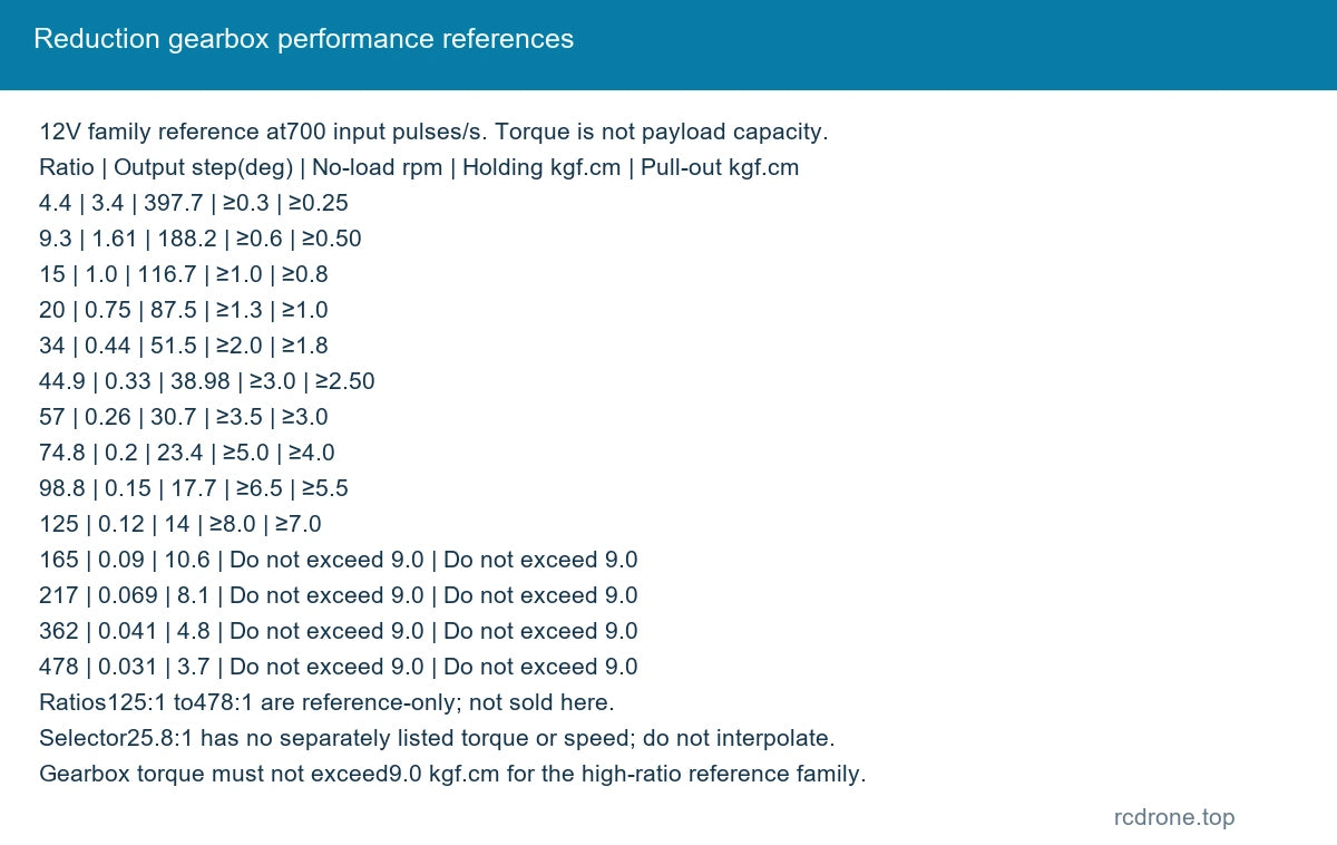
The following is a 12V family reference at 700 input pulses/s, not a guarantee for every selected package. Ratios above 100:1 are reference-only and are not sold here. Holding and pull-out torque are different; torque is not a payload rating.
| Reference ratio | Output step (°) | No-load rpm at 700 pps | Holding (kgf·cm) | Pull-out (kgf·cm) |
|---|---|---|---|---|
| 4.4 | 3.4 | 397.7 | ≥0.3 | ≥0.25 |
| 9.3 | 1.61 | 188.2 | ≥0.6 | ≥0.50 |
| 15 | 1.0 | 116.7 | ≥1.0 | ≥0.8 |
| 20 | 0.75 | 87.5 | ≥1.3 | ≥1.0 |
| 34 | 0.44 | 51.5 | ≥2.0 | ≥1.8 |
| 44.9 | 0.33 | 38.98 | ≥3.0 | ≥2.50 |
| 57 | 0.26 | 30.7 | ≥3.5 | ≥3.0 |
| 74.8 | 0.2 | 23.4 | ≥5.0 | ≥4.0 |
| 98.8 | 0.15 | 17.7 | ≥6.5 | ≥5.5 |
| 125 | 0.12 | 14 | ≥8.0 | ≥7.0 |
| 165 | 0.09 | 10.6 | Do not exceed 9.0 | Do not exceed 9.0 |
| 217 | 0.069 | 8.1 | Do not exceed 9.0 | Do not exceed 9.0 |
| 362 | 0.041 | 4.8 | Do not exceed 9.0 | Do not exceed 9.0 |
| 478 | 0.031 | 3.7 | Do not exceed 9.0 | Do not exceed 9.0 |
Mechanical Dimensions
All dimensions are millimetres. The original drawing specifies L ±0.3, a 2.5 mm front section, a 0.5 mm rear step, 6 mm rear boss, 3.7 mm connector offset and 9.2 mm connector height. Use the selected ratio and physical mounting drawing before machining; the 57:1 and 25.8:1 gearbox lengths are not separately specified.
| Actual ratio references | Gearbox length L (mm) | Gear stages |
|---|---|---|
| 4.4 / 9.3 / 15.46 / 20.41 | 19 | 2 / 3 / 4 / 4 |
| 34.01 / 44.9 | 21 | 5 |
| 74.83 / 98.78 | 23 | 6 |
| 164.63 / 217.31 | 25 | 7 |
| 362.18 / 478.08 | 27 | 8 |
Wiring and Control
Pin 1 yellow is phase B, pin 2 red is the opposite B winding end, pin 3 black is phase A, and pin 4 blue is the opposite A winding end. Coil pairs are yellow/red and black/blue. Use a bipolar stepper driver, not a direct DC connection. Rotation follows the phase excitation sequence; the drawing views rotation from the flange side.
The motor reference is 12V. A 5–24V driver-supply range is discussed for current-controlled operation; higher supply voltage requires appropriate current limiting and does not make every included board or power supply a 24V item. Set phase current appropriately. Guidance suggests starting near 300 pulses/s and increasing toward approximately 700 pulses/s; usable speed depends on load and acceleration. The general 100–1300 pulses/s control range and higher unloaded response references are not guaranteed starting frequencies.
Package Selection
| Package | Contents |
|---|---|
| Motor Only | One motor |
| Motor + Bracket | One motor + mounting bracket |
| Motor + Driver | One motor + push-button driver board |
| Motor + Enclosed Driver | One motor + driver in enclosure |
| Motor + Bracket + Driver | One motor + mounting bracket + push-button driver board |
| Motor + Power Supply + Driver | One motor + power supply + push-button driver board |
| Motor + Bracket + Power Supply + Driver | One motor + mounting bracket + power supply + push-button driver board |
The enclosed-driver option includes its case; other driver packages show an open board. Photographed adapter plug style and board revision are visual references; no unverified input rating or control-interface protocol is promised. Motor-only and bracket packages require a separate suitable driver and supply.
Applications
Use the motor for compact indexing, positioning, instrument adjustment and small robot mechanisms where discrete step control and reduction gearing are useful. Match required speed, torque, duty cycle and backlash tolerance to the actual mechanism.
What's Included
One selected motor configuration with its attached four-wire lead. The bracket, driver, enclosure and power supply are included only when named in the chosen package. No complete robot, external controller or other application assembly is included.
Installation and Operation
Keep within the rated load, including shaft loads. Check the coil pairs and current setting before power-up. Increase load gradually during commissioning. Avoid severe impacts and do not force or pry the gearbox shaft. Long operation, supply voltage, speed and load affect motor temperature; provide adequate cooling.
FAQ
Can this four-wire motor connect directly to DC power?
No. It needs the correct two-phase bipolar excitation from a suitable stepper driver.
Is the 25.8:1 option the same as 34:1?
No. It is a separate selectable ratio. Its own torque and gearbox length are not listed, so confirm the required mechanical envelope before installation.
Which packages include a power supply?
Only Motor + Power Supply + Driver and Motor + Bracket + Power Supply + Driver include one.
Visual Details