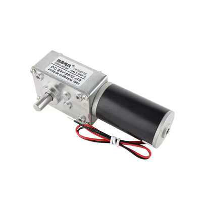
CHIHAI CHB-BLDC3525 Brushless Motor with Built-in Driver, 12V/24V
CHIHAI CHB-BLDC3525 Brushless Motor with Built-in Driver, 12V/24V
CHIHAI MOTOR
Impossibile caricare la disponibilità del ritiro


Overview
The CHIHAI MOTOR CHB-BLDC3525 brushless motor integrates a sensored Hall driver in a compact rotary housing. Choose the exact voltage/speed winding, shaft diameter and projection, and motor-only, open-controller or enclosed-controller package. This is a direct motor without a reduction gearbox.
Features
- Integrated Hall-sensored commutation and driver.
- Ball bearings at both ends and four-pole/six-slot magnetic construction.
- White-wire direction input and yellow-wire FG speed feedback.
- PWM or analog speed input, with a separate brake wiring mode.
- 9 mm or12 mm shaft references, with 2 mm or3 mm diameter according to available configuration.
Specifications
| Brand / model | CHIHAI MOTOR / CHB-BLDC3525 |
| Product | Direct brushless DC rotary motor with integrated sensored Hall driver; no reduction gearbox |
| Windings | 12 V /3000 rpm, 24 V /6000 rpm, and separate12 V /6000 rpm configurations |
| Shaft choices | 3 mm diameter: 9 mm or12 mm projection; 2 mm diameter: 9 mm projection only in retained options |
| Envelope | 35 mm class; drawings specify36 mm diameter and 26 mm overall motor reference, 22 mm body reference |
| Mounting | 4×M3 on25 mm pitch circle; screw penetration 2 mm maximum recommended, 2.5 mm absolute artwork limit |
| Construction | Ball bearings at both ends; four-pole/six-slot structure; integrated driver and coil protection board |
| Mass | Approximately66 g motor reference; controllers and shaft variants differ |
| Lead length | 270–280 mm nominal references; dimension drawings 280±10 mm |
| Direction and feedback | White direction input; yellow FG open-collector speed output; blue speed/brake input |
| Installation | Do not reverse red/black supply polarity. Excess screw penetration can contact the stator and damage windings/driver. |
Standard-Winding Performance
The following table applies to the 12 V /3000 rpm and 24 V /6000 rpm standard references. The12 V /6000 rpm option is a different winding; do not apply the 12 V /3000 rpm torque, current or output figures to it. No-load, rated and protection points are different operating conditions.
| Parameter | 12 V /3000 rpm reference | 24 V /6000 rpm reference |
|---|---|---|
| No-load speed | 3000±10%rpm | 6000±10%rpm |
| No-load current | ≤70 mA | ≤130 mA |
| Rated torque | 40gf.cm | 90gf.cm |
| Rated speed | 2300±10%rpm | 4600±10%rpm |
| Rated current | ≤280 mA | ≤400 mA |
| Rated output | 1.0 W | 4.3 W |
| Stall-protection torque | ≥170gf.cm | ≥380gf.cm |
| Stall-protection current | ≤0.85 A | ≤1.5 A |
Five-Wire Interface
Wrong wiring can damage the integrated driver. Red and black supply polarity must not be reversed. These five wires are control/supply connections for the integrated driver, not a set of three bare motor phases.
| Wire | Function | Electrical reference |
|---|---|---|
| Black | GND | DC supply negative / signal ground |
| Red | VCC | Selected motor positive supply; 12 V interface reference ±10%; match24 V winding separately |
| White | CW/CCW | Direction input 0–5 V; HI≥2 V: CCW; LO≤0.2 V: CW; open versus grounded selects direction |
| Yellow | FG | Open-collector output, 9 pulses per motor revolution; maximum5 mA sink |
| Blue | SPEED / BRAKE | 0–5 V PWM or1.2–3.3 V analog speed reference; brake-mode wiring disables speed adjustment |
FG high level is at least4 V with a 5 V/10kΩ pull-up; low level0–0.6 V. Use the 9-pulse-per-revolution output for speed measurement and respect the 5 mA output-current limit. The blue input reference spans0–5 V; analog speed regulation is specified over 1.2–3.3 V. Do not apply motor supply voltage to logic inputs.
Controller Modes
The controller illustrations show speed-adjustment wiring and brake wiring as separate modes. Brake wiring has no speed-adjustment function. Controller-family illustrations cover BLDC3525/3650/4260 and do not make these different motors interchangeable. The controller input reference is 6–30 V DC; never connect220 V AC directly. Match the controller, selected winding and control mode before connection.
Mechanical Dimensions and Mounting
| Configuration | Shaft projection | Motor overall | Front cap | Body reference | Diameter | Front boss diameter |
|---|---|---|---|---|---|---|
| 3 mm shaft /12 mm projection | 12±0.5 mm | 26±0.5 mm | 2.8±0.1 mm | 22±0.2 mm | 36±0.5 mm | 9.2 mm |
| 3 mm shaft /9 mm projection | 9±0.5 mm | 26±0.5 mm | 3±0.1 mm | 22±0.1 mm | 36±0.5 mm | 9 mm,+0.1/0 |
| 2 mm shaft /9 mm projection | 9±0.5 mm | 26±0.5 mm | 2.8±0.1 mm | 22±0.2 mm | 36±0.2 mm | 9.2 mm |
Dimensions are in mm. All drawings show fourM3 mounting holes on a 25 mm pitch circle, R1 edge reference and 280±10 mm lead length. Limit screw penetration to 2 mm for conservative installation; the coil-protection artwork allows only 2.0–2.5 mm and warns that longer screws can reach the stator/windings. Verify the actual motor and fastener stack before tightening.
Applications
Compact robotics, mechanical equipment, motorized curtains and doors, rotary automation and gimbal-like mechanisms where the selected speed, torque, shaft and controller are suitable. A robot, chassis, gearbox or complete positioning system is not included.
What's Included
- Motor Only: one selected CHB-BLDC3525 motor with its five-wire lead and integrated driver.
- Open Controller package: one motor and one pictured open control board.
- Enclosed Controller package: one motor and one pictured enclosed speed controller.
External power supply, mechanical equipment and feedback processor are not included. The integrated motor driver is present even in the motor-only option; the optional boards provide external control functions.
FAQ
Does the motor-only option need a separate commutation driver?
The motor contains its sensored driver. Connect the selected DC supply and control inputs correctly; an optional external control board is a separate package choice.
Does every configuration offer a 12 mm shaft with 2 mm diameter?
No. Those combinations were unavailable. Retained2 mm-diameter configurations have9 mm projection.
Can I adjust speed while using the illustrated brake mode?
The brake wiring illustration has no speed-adjustment function. Select the appropriate control mode.
How many FG pulses correspond to one motor revolution?
The interface reference specifies9 pulses per revolution from the yellow open-collector output.
How far may mounting screws enter the motor?
Keep penetration to 2 mm and verify the fastener stack. Longer screws can contact the internal stator and windings.
Visual Details