CHIHAI GF5560-180ABHL Worm DC Gear Motor with 11 PPR Hall Encoder
CHIHAI GF5560-180ABHL Worm DC Gear Motor with 11 PPR Hall Encoder
CHIHAI MOTOR
Impossibile caricare la disponibilità del ritiro


Overview
The CHIHAI MOTOR CHF-GF 5560-180ABHL is a compact DC gear motor with worm reduction and an integrated two-channel Hall encoder. Choose the voltage/winding and the actual reduction/output-face combination for your mechanism. Every selectable configuration includes the encoder-equipped motor and pictured matching lead.
Features
- Worm-and-gear reduction with machined gears and a copper-wound motor.
- 8 mm D-shaped output shaft with flat-face or axial R-face layout as selected.
- 11 PPR motor-shaft Hall feedback for relative speed and rotation measurement.
- Separate motor-power and Hall-supply connections through a PH 2.0 six-pin interface.
Specifications
| Brand / model | CHIHAI MOTOR / CHF-GF 5560-180ABHL |
| Construction | Brushed DC worm-and-gear reduction motor with AB magnetic Hall encoder |
| Selectable winding / supply | 6 V high-torque, 12 V high-torque, 24 V 24150# or 12 V 24150# as selected |
| Selectable reductions | 26.9: 1, 53.8: 1, 161: 1, 322: 1 flat-face; 700: 1 and 1400: 1 axial R-face; stock depends on winding |
| Output shaft | 8 mm diameter +0/−0.03; 7 mm across D-flat +0/−0.10; 21 ±0.5 mm projection |
| Shaft flat length | 15 mm +0/−0.2; 1.0 mm shoulder and 12.0 mm drawing feature |
| Flat-face outline | 55 ×60 mm drawing reference; 19 mm gearbox depth |
| Flat-face mounting | Four 3.5 mm through holes; 8.5/3.5/12.5 mm edge references; shaft center 22.2/16.6 mm reference |
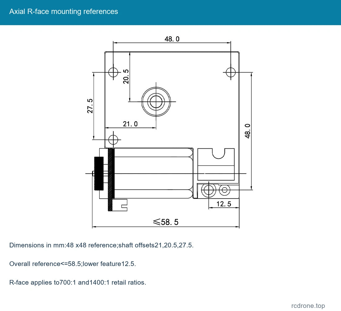
| R-face mounting drawing | 48 ×48 mm references; shaft center 21/20.5/27.5 mm; 12.5 mm lower feature; overall≤58.5 mm reference |
| Encoder rear details | 20.4 mm diameter reference, EVA insulating pad, PH 2.0six-pin connector |
| Reference net mass | Approximately 210 g; varies with ratio and winding; shipping mass is separate |
| Gear module / reduction stages | 0.5–0.8 module reference, four-stage gearbox family reference |
| Allowed rated-load ceiling | 25 kgf·cm maximum mechanical limit; not the rated torque of every variant |
| Instantaneous torque ceiling | 40 kgf·cm maximum mechanical limit; not continuous operating torque |
| Hall encoder | 11 PPR at motor shaft, AB quadrature feedback; 3.3 V or 5.0 V separate supply |
| Output pulse reference | 11 × actual reduction ratio before the controller's edge-counting multiplier |
Winding and Performance Reference
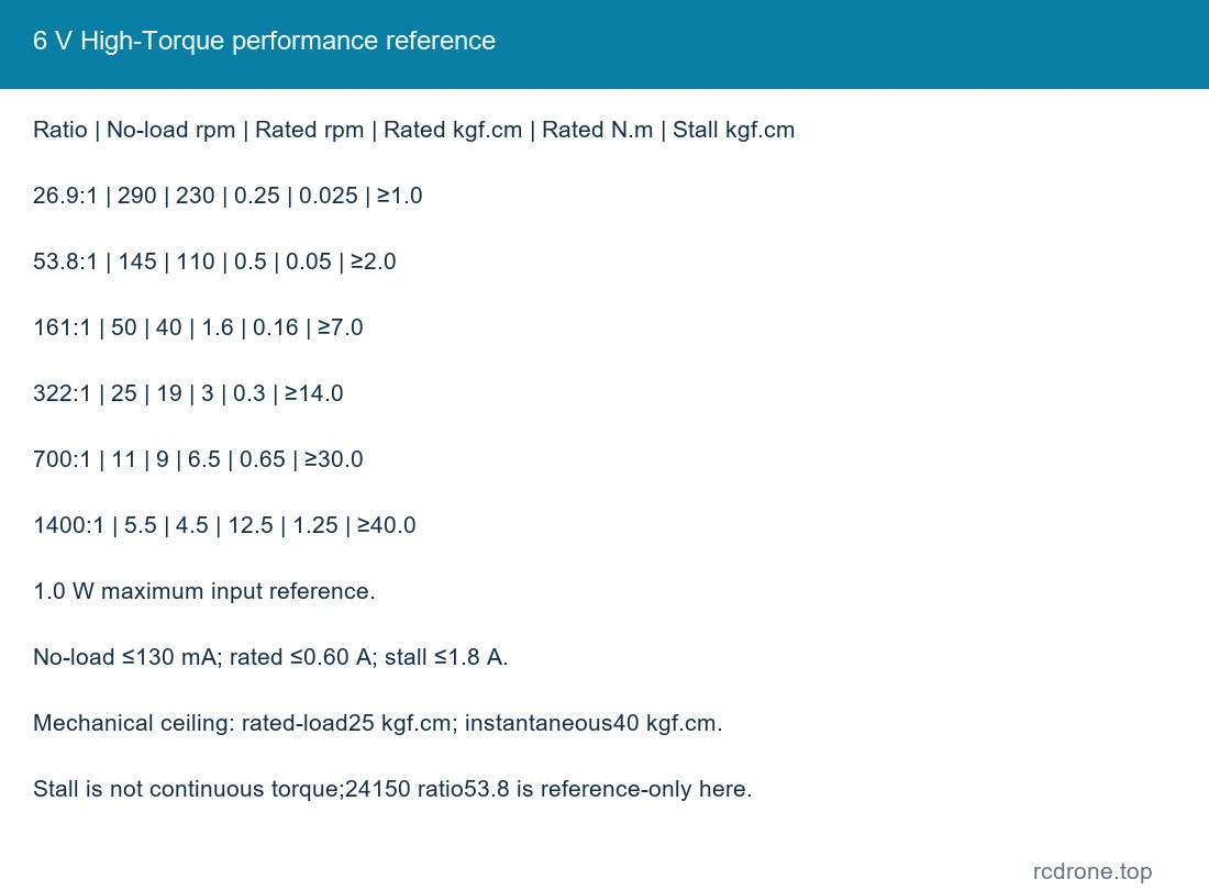
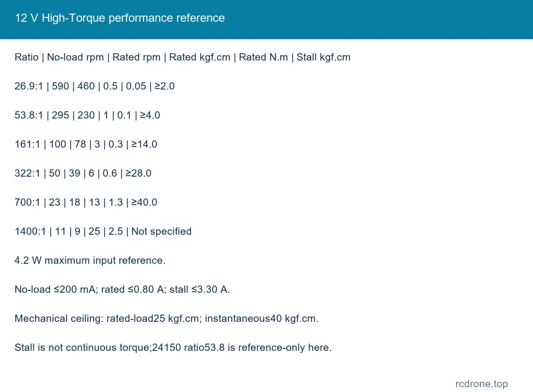
The following tables keep each winding and voltage separate. Rated-load torque is an operating reference; stall figures are not continuous torque ratings. Avoid stall and stay within the gearbox's 25 kgf·cm rated-load and 40 kgf·cm instantaneous mechanical ceilings. Power figures retain their stated input/reference scope and do not establish mechanical output power.
6 V High-Torque
1.0 W maximum input reference. No-load current ≤130 mA; rated current ≤0.60 A; stall current ≤1.8 A.
| Ratio | No-load rpm | Rated-load rpm | Rated kgf·cm | Rated N·m | Stall kgf·cm |
|---|---|---|---|---|---|
| 26.9: 1 | 290 | 230 | 0.25 | 0.025 | ≥1.0 |
| 53.8: 1 | 145 | 110 | 0.5 | 0.05 | ≥2.0 |
| 161: 1 | 50 | 40 | 1.6 | 0.16 | ≥7.0 |
| 322: 1 | 25 | 19 | 3 | 0.3 | ≥14.0 |
| 700: 1 | 11 | 9 | 6.5 | 0.65 | ≥30.0 |
| 1400: 1 | 5.5 | 4.5 | 12.5 | 1.25 | ≥40.0 |
12 V High-Torque
4.2 W maximum input reference. No-load current ≤200 mA; rated current ≤0.80 A; stall current ≤3.30 A.
| Ratio | No-load rpm | Rated-load rpm | Rated kgf·cm | Rated N·m | Stall kgf·cm |
|---|---|---|---|---|---|
| 26.9: 1 | 590 | 460 | 0.5 | 0.05 | ≥2.0 |
| 53.8: 1 | 295 | 230 | 1 | 0.1 | ≥4.0 |
| 161: 1 | 100 | 78 | 3 | 0.3 | ≥14.0 |
| 322: 1 | 50 | 39 | 6 | 0.6 | ≥28.0 |
| 700: 1 | 23 | 18 | 13 | 1.3 | ≥40.0 |
| 1400: 1 | 11 | 9 | 25 | 2.5 | Not specified |
24 V 24150 Winding
3.0 W maximum power reference; 15000 rpm motor input reference. No-load current ≤150 mA; rated current ≤0.550 A; stall current ≤2.3 A.
| Ratio | No-load rpm | Rated-load rpm | Rated kgf·cm | Rated N·m | Stall kgf·cm |
|---|---|---|---|---|---|
| 53.8: 1 | 278 | 200 | 0.8 | 0.08 | ≥3.5 |
| 161: 1 | 93 | 70 | 2.5 | — | ≥10.0 |
| 322: 1 | 47 | 36 | 5 | 0.5 | ≥20.0 |
| 700: 1 | 21 | 16 | 10 | 1 | ≥30.0 |
| 1400: 1 | 10.5 | 8 | 20 | 2 | ≥40.0 |
12 V 24150 Winding
1.0 W maximum power reference; 7500 rpm motor input reference. No-load current ≤120 mA; rated current ≤0.350 A; stall current ≤1.25 A.
| Ratio | No-load rpm | Rated-load rpm | Rated kgf·cm | Rated N·m | Stall kgf·cm |
|---|---|---|---|---|---|
| 53.8: 1 | 135 | 100 | 0.5 | 0.05 | ≥1.3 |
| 161: 1 | 45 | 33 | 1.5 | 0.15 | ≥4.0 |
| 322: 1 | 23 | 17 | 3 | 0.3 | ≥10.0 |
| 700: 1 | 10 | 8 | 6 | 0.6 | ≥18 |
| 1400: 1 | 5 | 4 | 12 | 1.2 | ≥30.0 |
The 24150 tables include 53.8: 1 as a family reference; that winding/ratio has no stocked retail choice here. The 26.9: 1 ratio is selectable only for the two high-torque windings. Other family ratios 89.6, 125.4, 179.2, 250.8, 388.90, 544.48, 777.8 and 1088.81 are reference/custom family sizes, not added as selectable retail combinations.
Encoder Connection
| Pin | Signal | Function |
|---|---|---|
| 1 | M 1 | Motor DC supply positive |
| 2 | GND | Hall ground |
| 3 | C 2 / B | Hall channel B output |
| 4 | C 1 / A | Hall channel A output |
| 5 | VCC | Hall 3.3 V or 5 V supply |
| 6 | M 2 | Motor DC supply negative |
Pin 1 and pin 6 refer to the connector orientation shown in the dimension drawing. Match the actual connector and silk-screen before connection. Never apply the 6/12/24 V motor supply to Hall VCC or A/B signal pins. Hall supply is 3.3 V or 5 V and must match the receiving logic levels.
11 PPR is the base motor-shaft pulse reference; gearbox-output pulse reference scales with reduction ratio. Controller x 1/x 2/x 4 edge-counting modes change counted edges, not the underlying magnetic pole reference. Incremental feedback does not give absolute position after power-up.
Photographs illustrate a12 V,322:1 marked example. Supply,ratio and output face follow the selected option.
Mechanical Fit and Operation
Use the selected flat-face or R-face drawing when locating mounting holes. Check screw length, shaft/hub fit and encoder clearance before assembly. Provide current capacity and protection for the selected winding; stall current is substantially higher than normal running current. Noise and temperature vary with load and speed. Avoid overload, stall and abrupt reversal under load; keep debris away from gears and the encoder.
Applications
Compact automation, positioning mechanisms and robotic drive projects requiring geared rotation with speed and relative-rotation feedback. Select the actual torque, speed, mounting layout and controller interface for the application.
What's Included
One selected encoder-equipped CHF-GF 5560-180ABHL motor and the pictured matching six-wire connector lead. A power supply, motor controller, external counter, bracket, complete robot and extra loose gears are not included. Internal-construction pictures illustrate components inside one motor.
FAQ
Does every option include an encoder?
Yes. All retained options are the ABHL encoder version; the ordinary GF 5560-180 motor is a different configuration.
Can the Hall board use motor voltage?
No. Supply the Hall circuit separately at 3.3 V or 5 V.
Can I choose either output face at every ratio?
No. The actual options pair 26.9/53.8/161/322 ratios with the flat face and 700/1400 with the R-face.
Can I use the stall-torque number as continuous torque?
No. Use the selected winding's rated-load reference and the gearbox mechanical limits.
Visual Details