CHIHAI GW12T-N20ABHL Worm DC Gear Motor with 7 PPR Hall Encoder
CHIHAI GW12T-N20ABHL Worm DC Gear Motor with 7 PPR Hall Encoder
CHIHAI MOTOR
Impossibile caricare la disponibilità del ritiro


Overview
The CHIHAI MOTOR CHF-GW 12T-N 20ABHL is a miniature DC gear motor with worm reduction and an AB magnetic Hall encoder. Choose the physical lead layout, reduction ratio and voltage/winding. Every actual option includes the encoder-equipped motor and matching six-wire connector lead; the listing is not a complete robot chassis or controller kit.
Features
- Metal worm-and-reduction gear train in a compact frame.
- 3 mm D-shaped output shaft with 8 mm projection reference.
- 7 PPR motor-shaft AB feedback for relative speed and rotation measurement.
- A 35 and B 45 motor windings with separate voltage-specific data.
Specifications
| Brand / model | CHIHAI MOTOR / CHF-GW 12T-N 20ABHL; family images also mark GW 12T-N 20VA |
| Construction | Miniature brushed DC worm-and-gear motor with AB Hall encoder |
| Winding choices | 12 V A 35, 6 V A 35, 6 V B 45 or 3 V B 45 as actual stocked combination |
| Ratio choices | 42: 1, 118: 1, 236: 1, 302: 1, 603: 1, 1030: 1; steel-plate 1030 source combination excluded when zero-stock |
| Lead layout | Same-side or opposite-side soldering layout as pictured; not a commanded rotation direction |
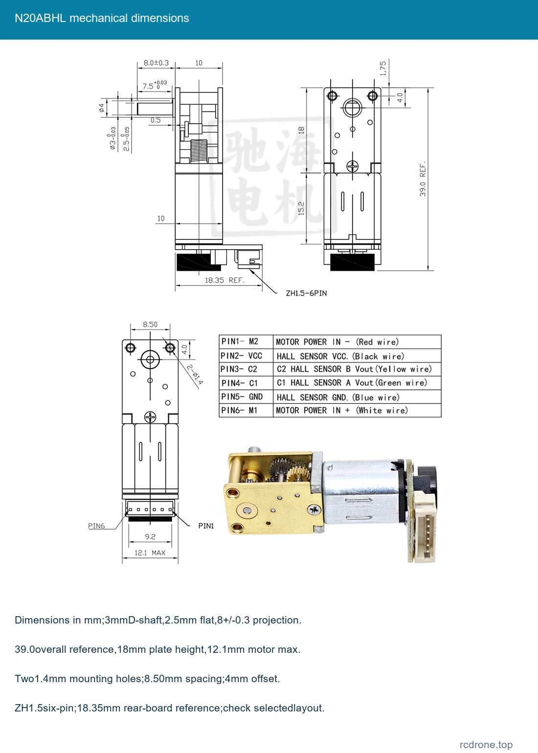
| Shaft | 3 mm D-shaped output, 2.5 mm across flat, 8±0.3 mm projection |
| Shaft details | 7.5 mm collar reference,+0.03/0; 0.5 mm shoulder feature |
| Mechanical drawing | 39.0 mm overall reference; 18 mm gear plate height; 10 mm gear section and 15.2 mm motor references |
| Mounting | Two 1.4 mm holes; 8.50 mm spacing; 4.0 mm reference offset; 1.75 mm edge reference |
| Motor / encoder envelope | 12.1 mm motor maximum; 18.35 mm rear-board reference; ZH 1.5 six-pin connector |
| Reference net mass | Approximately 15 g; shipping mass is separate |
| Hall feedback | AB incremental magnetic Hall, 7 PPR motor shaft, 14 poles/7 pole pairs |
| Hall supply / outputs | 3.3 V or 5 V separate supply; AB square waves, onboard pull-up/signal-shaping resistors |
| Response / lead | 100 kHz reference; matchingZH 1.5-6PIN lead included |
| Holding behavior | Worm-drive resistance to back-driving depends on ratio and load; not a safety-rated brake |
Winding-Specific Performance
Use the row for the actual winding and ratio. Rated and stall torque are different conditions. Stall-torque figures are upper-limit references and are not continuous load ratings. Power labels describe each winding reference without guaranteeing output power at every operating point.
12 V A 35
0.2 W reference.
| Ratio | No-load mA | No-load rpm | Rated kgf·cm | Rated rpm | Rated A | Stall A | Stall kgf·cm |
|---|---|---|---|---|---|---|---|
| 42: 1 | ≤65 | 550 | 0.05 | 390 | ≤0.15 | ≤0.4 | ≤0.16 |
| 118: 1 | ≤65 | 200 | 0.15 | 140 | ≤0.15 | ≤0.4 | ≤0.4 |
| 236: 1 | ≤65 | 100 | 0.3 | 70 | ≤0.15 | ≤0.4 | ≤0.8 |
| 302: 1 | ≤65 | 78 | 0.4 | 55 | ≤0.15 | ≤0.4 | ≤1.1 |
| 603: 1 | ≤65 | 39 | 0.8 | 27 | ≤0.15 | ≤0.4 | ≤2 |
| 1030: 1 | ≤65 | 22 | 1.2 | 15 | ≤0.15 | ≤0.4 | ≤3 |
6 V A 35
0.1 W reference.
| Ratio | No-load mA | No-load rpm | Rated kgf·cm | Rated rpm | Rated A | Stall A | Stall kgf·cm |
|---|---|---|---|---|---|---|---|
| 42: 1 | ≤35 | 275 | 0.02 | 195 | ≤0.08 | ≤0.2 | ≤0.07 |
| 118: 1 | ≤35 | 98 | 0.07 | 70 | ≤0.08 | ≤0.2 | ≤0.2 |
| 236: 1 | ≤35 | 49 | 0.15 | 35 | ≤0.08 | ≤0.2 | ≤0.4 |
| 302: 1 | ≤35 | 37 | 0.2 | 27 | ≤0.08 | ≤0.2 | ≤0.5 |
| 603: 1 | ≤35 | 19 | 0.4 | 13 | ≤0.08 | ≤0.2 | ≤1 |
| 1030: 1 | ≤65 | 11 | 0.6 | 7 | ≤0.15 | ≤0.4 | ≤1.5 |
6 V B 45
0.6 W reference.
| Ratio | No-load mA | No-load rpm | Rated kgf·cm | Rated rpm | Rated A | Stall A | Stall kgf·cm |
|---|---|---|---|---|---|---|---|
| 42: 1 | ≤80 | 530 | 0.06 | 390 | ≤0.2 | ≤0.65 | ≤0.16 |
| 118: 1 | ≤80 | 190 | 0.16 | 140 | ≤0.2 | ≤0.65 | ≤0.4 |
| 236: 1 | ≤80 | 94 | 0.32 | 70 | ≤0.2 | ≤0.65 | ≤0.8 |
| 302: 1 | ≤80 | 74 | 0.4 | 55 | ≤0.2 | ≤0.65 | ≤1.1 |
| 603: 1 | ≤80 | 37 | 0.8 | 27 | ≤0.2 | ≤0.65 | ≤2 |
| 1030: 1 | ≤80 | 22 | 1.3 | 15 | ≤0.2 | ≤0.65 | ≤3 |
3 V B 45
0.15 W reference.
| Ratio | No-load mA | No-load rpm | Rated kgf·cm | Rated rpm | Rated A | Stall A | Stall kgf·cm |
|---|---|---|---|---|---|---|---|
| 42: 1 | ≤35 | 260 | 0.03 | 195 | ≤0.15 | ≤0.35 | ≤0.07 |
| 118: 1 | ≤35 | 90 | 0.08 | 65 | ≤0.15 | ≤0.35 | ≤0.2 |
| 236: 1 | ≤35 | 45 | 0.16 | 33 | ≤0.15 | ≤0.35 | ≤0.4 |
| 302: 1 | ≤35 | 35 | 0.2 | 26 | ≤0.15 | ≤0.35 | ≤0.5 |
| 603: 1 | ≤35 | 18 | 0.4 | 13 | ≤0.15 | ≤0.35 | ≤1 |
| 1030: 1 | ≤35 | 11 | 0.65 | 7 | ≤0.15 | ≤0.35 | ≤1.5 |
Hall Encoder Connection
| Pin | Wire color | Signal | Function |
|---|---|---|---|
| 1 | Red | M 2 | Motor negative |
| 2 | Black | VCC | Hall supply positive 3.3/5V |
| 3 | Yellow | C 2 / B | Hall phaseB output |
| 4 | Green | C 1 / A | Hall phaseA output |
| 5 | Blue | GND | Hall supply ground |
| 6 | White | M 1 | Motor positive |
Pin order follows the mechanical connector drawing. Match actual markings and connector orientation before connection. Never apply the motor supply to Hall VCC or signal inputs. Supply the Hall board separately at 3.3 V or 5 V with compatible receiver logic. Changing motor lead polarity reverses rotation while Hall power polarity remains fixed.
7 PPR is the motor-shaft base reference. Output pulse reference scales with the actual reduction ratio and receiver edge-counting mode. The detailed chart gives 294, 826.469, 1652.931, 2112.082, 4224.164 and 7212.8 pulses for its six ratio columns; these use actual reductions behind the nominal selector labels. Do not replace these decimals with a precise claim based only on rounded nominal ratios. Incremental feedback is relative and does not provide an absolute startup position.
Selection and Installation
Same-Side and Opposite-Side Lead Layout refer to the soldering/connector arrangement pictured relative to the output shaft, not a clockwise/counterclockwise command. Check the selected layout, shaft fit, mounting screws and encoder clearance before assembly. Steel-plate 1030 combinations have no source stock and are not selectable.
Use a suitable motor driver with startup-current margin and protection. Keep debris out of the exposed gears and encoder, avoid stall and abrupt reversal under load, and do not use worm holding behavior as a safety brake. No continuous-duty or certified payload rating is supplied.
Applications
Compact robot mechanisms, small motion projects and miniature pan-tilt or adjustment assemblies needing geared rotation and relative encoder feedback. A compatible external microcontroller and motor driver are required for feedback control.
What's Included
One selected Hall-encoder N 20 worm gear motor and matching six-wire lead. Chassis, wheels, battery, power supply, microcontroller, motor driver and complete robot are not included. Internal-construction pictures illustrate parts inside one motor.
FAQ
Does every option include the encoder?
Yes. These actual options are ABHL feedback versions.
Do Same-Side and Opposite-Side control rotation?
No. They identify the physical lead layout; rotation depends on the motor drive polarity.
Can I use motor voltage for Hall power?
Use a separate 3.3 V or 5 V Hall supply and match the selected motor winding independently.
Is a robot chassis included?
No. The package contains one motor and its matching lead.
Visual Details