HUMANETICS Y75-H32 Six-Axis Force/Torque Sensor, RS485 / CAN / CAT
HUMANETICS Y75-H32 Six-Axis Force/Torque Sensor, RS485 / CAN / CAT
HUMANETICS
Impossibile caricare la disponibilità del ritiro


Overview
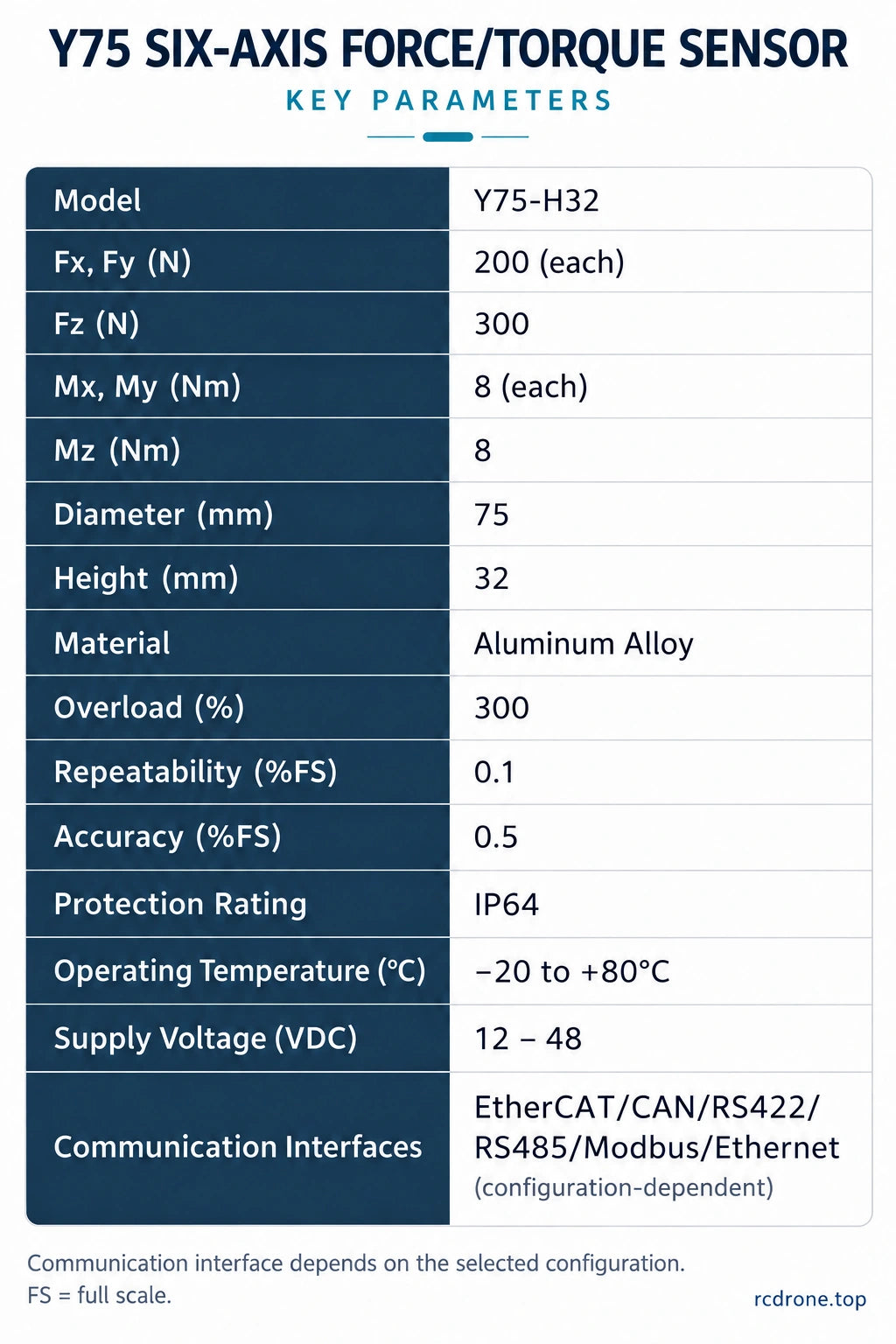
The HUMANETICS Y75-H32 six-axis force/torque sensor measures three force components and three moments for robotic assembly, surface finishing and force-feedback research. Its aluminum-alloy body measures 75 mm in diameter and 32 mm high. Choose an RS485, CAN or CAT/EtherCAT sensor configuration to suit your control system. A separate data acquisition unit is also available for measurement and setup applications.
Features
- Six-axis measurement: capture Fx, Fy and Fz forces together with Mx, My and Mz moments for multi-directional load feedback.
- Compact aluminum-alloy construction: integrate the 75 mm body into robot-wrist adapters and test fixtures.
- Configuration choices: select RS485, CAN or CAT/EtherCAT communication for your integration.
- Measurement consistency: 0.5% FS accuracy and 0.1% FS repeatability.
- Industrial integration: IP64 protection, a 12–48 VDC supply range and operation from −20 to +80 °C.
Specifications
| Model | Y75-H32 |
|---|---|
| Measurement axes | Fx, Fy, Fz; Mx, My, Mz |
| Fx / Fy measurement range | 200 N per axis |
| Fz measurement range | 300 N |
| Mx / My / Mz measurement range | 8 N·m per axis |
| Body diameter / height | 75 mm / 32 mm |
| Material | Aluminum alloy |
| Accuracy | 0.5% FS |
| Repeatability | 0.1% FS |
| Overload rating | 300% |
| Ingress protection | IP64 |
| Operating temperature | −20 to +80 °C |
| Supply voltage | 12–48 VDC |
| Selectable sensor interfaces | RS485; CAN; CAT / EtherCAT (configuration dependent) |
FS means full scale. Axis ranges are measurement ratings, not robot payload ratings. Check combined loading against the limits for your configuration; the overload rating is not a continuous operating range.
Configuration Guide
| Selection | Product |
|---|---|
| Y75-H32 sensor — RS485 | One sensor with RS485 communication. |
| Y75-H32 sensor — CAN | One sensor with CAN communication. |
| Y75-H32 sensor — CAT / EtherCAT | One CAT/EtherCAT sensor configuration. Check protocol and controller integration files before installation. |
| Data acquisition unit only | One separate acquisition unit; sensor not included. |
The interfaces are alternative configurations. RS422, Modbus and Ethernet are additional Y75-series communication choices; availability depends on the configuration. Before integration, check protocol, baud rate, sampling rate, connector pinout and controller/software compatibility for your selected unit.
Applications
- Precision assembly: measure insertion and contact forces to help tune alignment and force-controlled assembly routines.
- Grinding and surface finishing: provide force feedback for controlling tool contact during robotic processing.
- Handling and hand-guiding: measure forces and moments at the wrist to support interaction and handling control development.
- Robotics research and test fixtures: study multi-axis contact loads and force/position control with a suitably integrated controller.
Compliant motion and robot safety depend on the complete mechanical, electrical and control-system integration.
Mechanical Dimensions and Installation
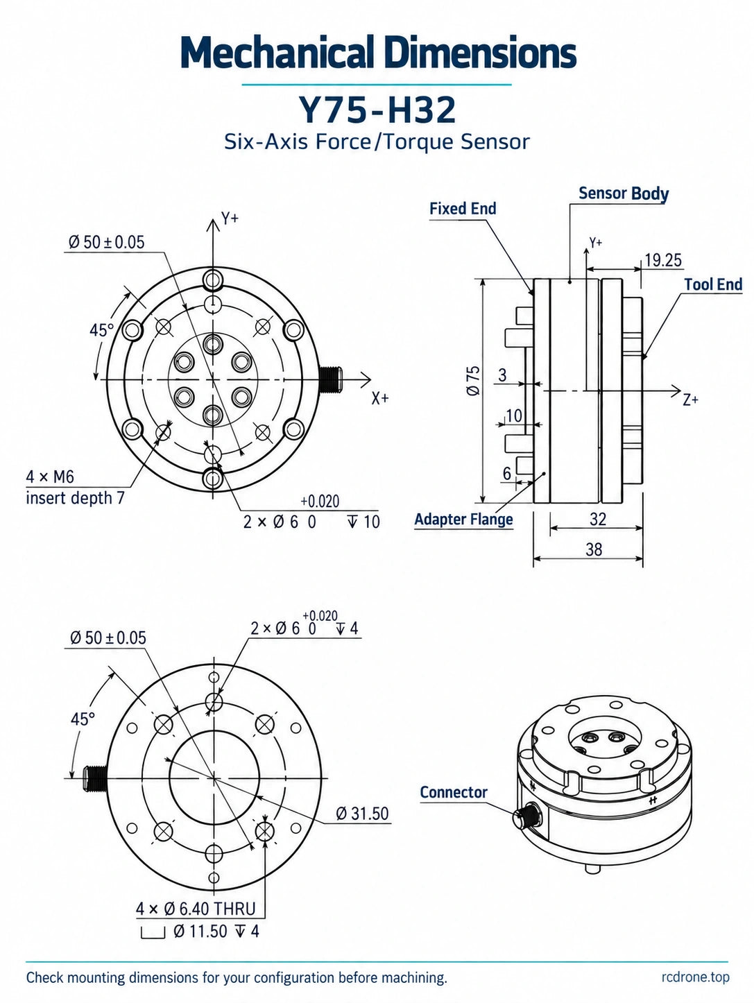
The dimensional drawing includes a 75 mm body diameter, 32 mm body height, 38 mm assembly-height callout and 50 ±0.05 mm mounting-circle references. Further callouts include 45°, 19.25 mm, 3 mm, 10 mm, 6 mm and Ø31.50 mm; hole details include 2 × Ø6 (+0.020/0), 10 mm and 4 mm depth callouts, 4 × M6 with 7 mm insert depth, and 4 × Ø6.40 through-holes with Ø11.50 counterbores, 4 mm deep. Read these dimensions with their corresponding views in Visual Details.
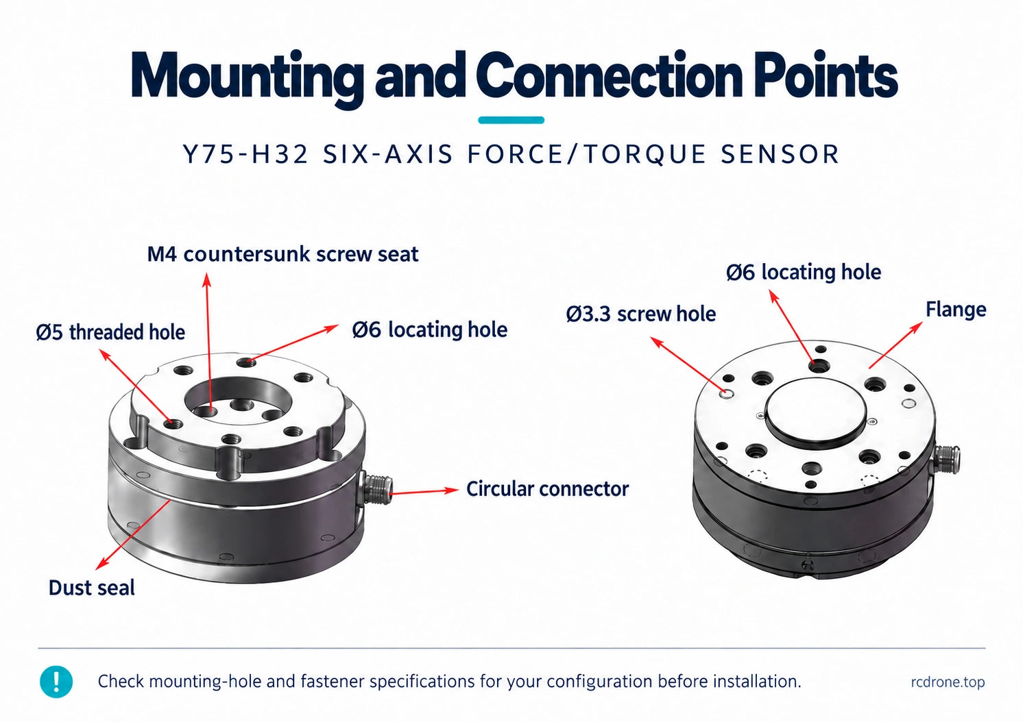
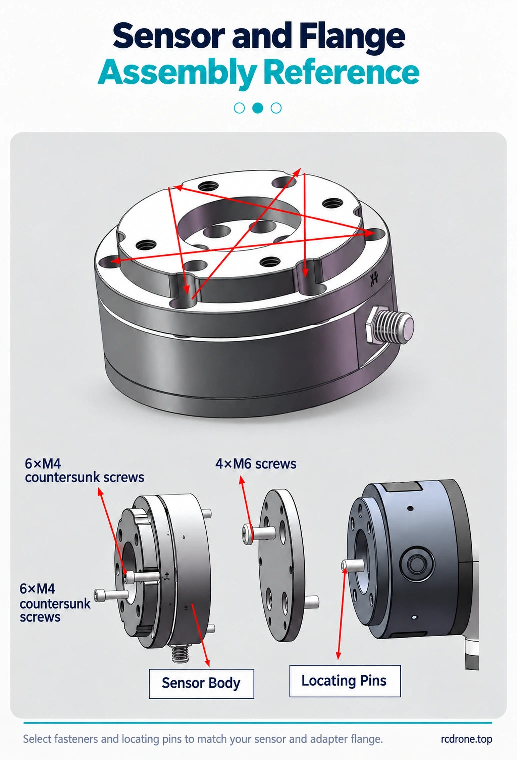
The mounting illustrations also identify M4 countersunk seats, Ø5 threaded holes, Ø6 locating holes, Ø3.3 screw holes, a circular connector, dust seal and adapter flange. The assembly illustration shows 6 × M4 and 4 × M6 fasteners. Hole and fastener details vary between the illustrated mounting views: check the mounting drawing for your configuration before machining an adapter or selecting screws and locating pins.
- Inspect the equipment, adapter flange and sensor.
- Separate the adapter flange and secure it to the equipment.
- Mount the sensor to the adapter using the matching fasteners and locating features.
- Attach the tooling, complete wiring and controller setup, then perform zeroing and any required compensation or calibration.
Route the flexible cable clear of moving parts and provide strain relief. Match connector pinout and electrical requirements before applying power.
Data Acquisition and Software
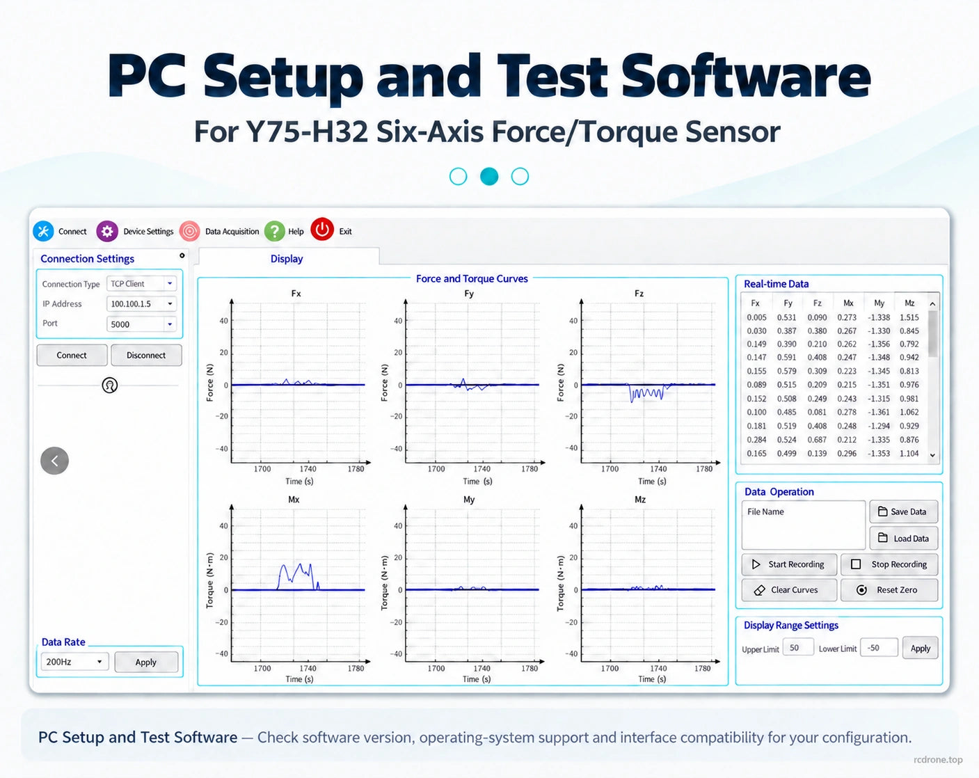
The separately sold ZKMD-CIQ-1.0 data acquisition unit measures 125 × 78 × 30 mm. Its connections include Ethernet and RS485 RJ45 ports, a 16-pin circular connector and a separate power connector, with power and status indicators. PC setup and test software supports signal display, decoupling and calibration. Check the hardware pinout, electrical input, software version, operating-system support and interface compatibility for your sensor configuration.
What's Included
- Sensor selections: 1 × Y75-H32 sensor in the selected RS485, CAN or CAT/EtherCAT configuration. The separate acquisition unit is not included.
- Data acquisition unit only: 1 × acquisition unit. A force/torque sensor is not included.
Robot arms, grippers, humanoid robots, workstations and application fixtures shown in the images are not included. Cable length and fastener contents depend on the selected package; check these requirements when planning installation. Humanoid wrist and foot images illustrate force-sensing applications; assess the 75 mm sensor dimensions and load ranges for your mounting location.
Visual Details