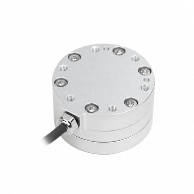
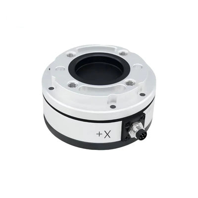
Kunwei Sensing KWR96 Series 6-Axis Force/Torque Sensor, 96 mm Diameter for Industrial Robots
Kunwei Sensing KWR96 Series 6-Axis Force/Torque Sensor, 96 mm Diameter for Industrial Robots
Kunwei Sensing
Impossibile caricare la disponibilità del ritiro


Overview
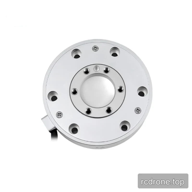
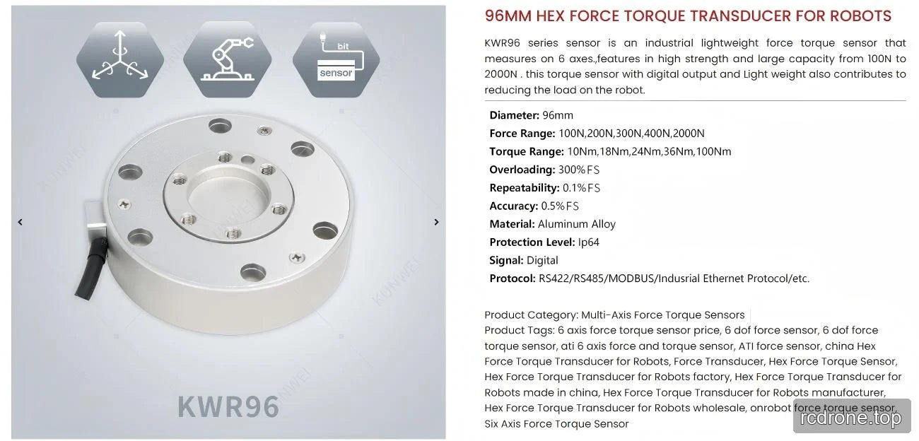
The Kunwei Sensing KWR96 Series is a six-axis force/torque sensor for industrial robot sensing, measuring forces Fx, Fy and Fz and torques Mx, My and Mz. Its 96 mm diameter and 26 mm height support mechanical integration into robot tooling. Six versions, KWR96A–KWR96F, offer different measurement ranges, accuracy, overload levels and sampling frequencies, allowing selection around the loads and measurement requirements of the task.
Features
- Six-axis measurement combines three force components and three torque components.
- Digital signal output with a series-level listing of serial, CAN, Ethernet and USB communication interfaces.
- Aluminum-alloy construction across all six versions; KWR96A–KWR96E are anodized, while KWR96F is electropolished.
- All versions have a 96 mm diameter, 26 mm height, 12–48 VDC supply range and −10 to 80 °C working temperature range.
- KWR96A–KWR96D offer 0.03% FS resolution and 300% FS overload level; KWR96E–KWR96F offer higher force and torque ranges with 0.05% FS resolution and 200% FS overload level.
Specifications
Version Comparison
| Parameter | Unit | KWR96A | KWR96B | KWR96C | KWR96D | KWR96E | KWR96F |
|---|---|---|---|---|---|---|---|
| Range Fx, Fy | N | 100 | 200 | 300 | 400 | 2000 | 3000 |
| Range Fz | N | 200 | 400 | 600 | 800 | 2000 | 4000 |
| Range Mx, My | N·m | 10 | 18 | 24 | 36 | 100 | 120 |
| Range Mz | N·m | 10 | 18 | 24 | 30 | 100 | 120 |
| Diameter | mm | 96 | 96 | 96 | 96 | 96 | 96 |
| Height | mm | 26 | 26 | 26 | 26 | 26 | 26 |
| Material | — | Aluminum alloy | Aluminum alloy | Aluminum alloy | Aluminum alloy | Aluminum alloy | Aluminum alloy |
| Surface treatment | — | Anodized | Anodized | Anodized | Anodized | Anodized | Electropolished |
| Overload level | % FS | 300 | 300 | 300 | 300 | 200 | 200 |
| Resolution | % FS | 0.03 | 0.03 | 0.03 | 0.03 | 0.05 | 0.05 |
| Repeatability | % FS | 0.1 | 0.1 | 0.1 | 0.1 | 0.3 | 0.3 |
| Accuracy* | % FS | 0.5 | 0.5 | 0.5 | 0.5 | 3 | 3 |
| Weight | kg | 0.32 | 0.32 | 0.36 | 0.36 | 1.6 | 1.65 |
| Protection level | — | IP64 | IP64 | IP64 | IP64 | IP64 | IP65 |
| Working temperature | °C | −10 to 80 | −10 to 80 | −10 to 80 | −10 to 80 | −10 to 80 | −10 to 80 |
| Sampling frequency | Hz | 1000 | 1000 | 1000 | 1000 | 100 | 1000 |
| Supply voltage* | VDC | 12–48 | 12–48 | 12–48 | 12–48 | 12–48 | 12–48 |
| Communication interface | — | RS422 / RS485 / MODBUS / CAN / CANFD / TCP / UDP / EtherCAT / USB, etc. — series-level interface listing | |||||
FS means full scale. Accuracy and supply voltage retain their source asterisk markers.
Signal and Communication Details
Output is digital. The series communication descriptions additionally identify Modbus-RTU and Industrial Ethernet Protocol. The listed interfaces are not identified as separate selectable configurations.
Mechanical Dimensions and Connection Details
The KWR96 mechanical reference defines the tool side, mounting side and reference surface, with X+, Y+ and Z+ coordinate directions.
| Location or parameter | Dimension or detail |
|---|---|
| Outside diameter | 96 mm |
| Lower side-view vertical dimensions | 25 mm and 26 mm |
| Tool-side hole circle | 78 mm diameter |
| Tool-side threaded holes | 6 × M5, 10 mm depth |
| Tool-side diameter feature | 40 mm diameter; concentricity tolerance 0.03 mm relative to datum A |
| Tool-side pin holes | 2 × 5 mm diameter, +0.02/0 mm diameter tolerance, 6 mm depth |
| Tool-side pin-hole position | Positional tolerance 0.03 mm relative to datum A |
| Tool-side angular layout | 26° offsets |
| Section A–A hole diameters | 9 mm and 5.5 mm |
| Section A–A axial dimensions | 22 mm and 15 mm |
| Side-view internal diameter | 30 mm nominal |
| Side-view diameter feature | 48 mm |
| Recessed feature axial dimension | 6 mm |
| Mounting-side hole circle | 78 mm diameter, ±0.05 mm tolerance |
| Mounting-side 78 mm diameter feature | Concentricity tolerance 0.03 mm relative to datum A |
| Mounting-side pin holes | 2 × 5 mm diameter, +0.02/0 mm diameter tolerance, 6 mm depth |
| Mounting-side pin-hole position | Positional tolerance 0.03 mm relative to datum A |
| Mounting-side angular layout | 26° offsets and 120° spacing |
| Cable reference dimensions | 6.0 mm diameter; 5 m length |
| Mechanical-reference precision | 0.1% FS |
Applications
- Industrial robot tool-contact monitoring: Measure three force components and three torque components to characterize loading during contact tasks, rather than relying on a single force direction.
- Robot tooling load and torque measurement: Select the version around the expected loads on each axis. For example, KWR96D has 36 N·m ranges on Mx and My but a 30 N·m range on Mz; KWR96F provides 120 N·m on all three torque axes.
- Time-varying robot load recording: Use the version-specific sampling frequency when planning measurements: KWR96E is specified at 100 Hz, while KWR96A–KWR96D and KWR96F are specified at 1000 Hz.
Documents
- KUNWEI KWR96 Drawing Series — Drawing (PDF)
- Kunwei KWR63 Series RS485 — User Manual (PDF)
- Kunwei KWR96 RS422 — User Manual (PDF)
- KUNWEI KWR75 RS422 — User Manual (PDF)
- KUNWEI 6 Axis Force Sensors Selection — Manual (PDF)
FAQ
What changes between KWR96A–KWR96F?
The versions differ in force and torque ranges, overload level, resolution, repeatability, accuracy, weight, surface treatment, protection level and sampling frequency. Diameter, height, material, supply voltage range and working temperature range are shared.
Does every version sample at 1000 Hz?
No. KWR96E is specified at 100 Hz. KWR96A, KWR96B, KWR96C, KWR96D and KWR96F are specified at 1000 Hz.
Are the torque ranges identical on every axis?
They are identical across Mx, My and Mz for KWR96A, KWR96B, KWR96C, KWR96E and KWR96F. KWR96D has a 36 N·m range on Mx and My and a 30 N·m range on Mz.
Visual Details
Specifications and Performance
Dimensions and Construction

Application Examples