CHIHAI MOTOR GW12T-050 DC Worm Gear Motor, Hall Encoder Options
CHIHAI MOTOR GW12T-050 DC Worm Gear Motor, Hall Encoder Options
CHIHAI MOTOR
受け取り可能状況を読み込めませんでした


Overview
The CHIHAI MOTOR CHF-GW12T-050 compact DC gear motor combines a right-angle metal worm gearbox with 6V or 12V winding choices and six reduction ratios. Choose the AB Hall encoder version with same-side or opposite-side motor terminals, or the rear-shaft motor without an encoder board.
Features
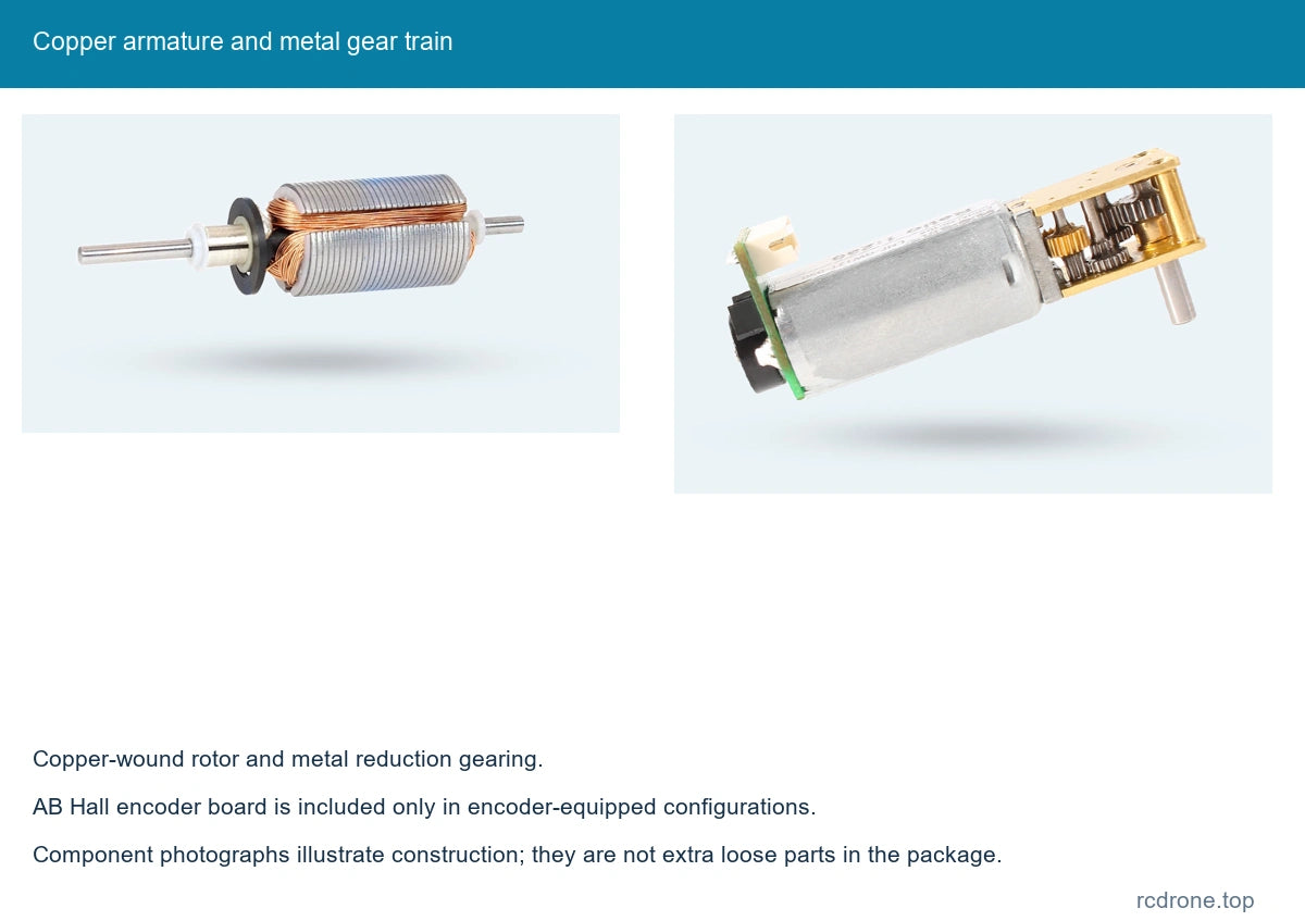
- Compact metal reduction gearing and copper-wound motor armature.
- Six output ratios from 42:1 to 1030:1 for speed and torque selection.
- Encoder-equipped configurations provide two-phase A/B feedback for direction and rotation sensing.
- 3 mm D-shaped output shaft and compact mounting geometry.
- Matching six-pin lead shown with encoder-equipped motor options.
Specifications
| Brand / model | CHIHAI MOTOR / CHF-GW12T-050ABHL encoder family; rear-shaft motor option also offered |
|---|---|
| Motor supply | Select 6V or 12V DC winding; encoder supply is separate |
| Gear train | Metal worm and reduction gears; steel-plate construction explicitly listed on 42, 236, 302, 603 and 1030 ratios; 118 housing material not specified in selector |
| Reduction ratios | 42:1, 118:1, 236:1, 302:1, 603:1, 1030:1 |
| Output shaft | 3 mm diameter (+0 / −0.03); 2.5 mm D-flat (+0 / −0.05); 8.0 ±0.3 mm projection |
| Reference dimensions | 50.0 mm overall reference; 32.0 mm motor reference; 18.0 ×12.0 mm gear-plate reference |
| Drawing details | 4.0 mm shaft-end offset; 8.50 mm mounting-hole spacing; 2 ×1.4 mm holes; 1.8 mm edge offset; 0.5 mm collar feature; 7.5 mm shoulder (+0.03 / 0) |
| Reference section | 10.0 mm plate spacing; 11.8 mm external height; 15.5 mm diagonal reference; 18.5 mm encoder-board width |
| Reference motor mass | Approximately 25 g; ratio and configuration affect actual mass |
| Encoder type | AB dual-channel incremental magnetic Hall encoder, on encoder-equipped options only |
| Encoder supply | 3.3V DC or 5.0V DC |
| Encoder connector | ZH1.5-6PIN, matching lead included with pictured encoder options |
| Encoder signal | A/B square-wave signals; onboard pull-up / signal-shaping resistors; connect to compatible MCU input levels |
| Encoder base pulses | 7 PPR at motor shaft; output-shaft pulse reference = 7 × reduction ratio |
| Encoder magnetic ring | 14 poles / 7 pole pairs |
| Encoder response frequency | 100 kHz |
| Orientation choices | Same-side or opposite-side motor-terminal arrangement relative to output shaft, as pictured; not a commanded rotation direction |
| Rear-shaft option | Motor with a rear shaft and without the Hall encoder board shown on encoder-equipped options |
Speed and Torque by Configuration
Use the table for the chosen winding and reduction ratio. Power references apply to the illustrated 11-size input motor: 0.55 W at 12V and 0.15 W at 6V. Speed, current and torque are different operating quantities; no-load speed is not rated load speed.
12V performance
| Ratio | No-load rpm | Rated rpm | Rated kgf·cm | Rated N·m | Stall torque reference, kgf·cm |
|---|---|---|---|---|---|
| 42:1 | 380 | 300 | 0.1 | 0.01 | ≤0.35 |
| 118:1 | 135 | 105 | 0.3 | 0.03 | ≤1.0 |
| 236:1 | 68 | 53 | 0.65 | 0.064 | ≥2.5 |
| 302:1 | 53 | 41 | 0.8 | 0.079 | Not specified |
| 603:1 | 27 | 20 | 1.6 | 0.16 | Not specified |
| 1030:1 | 16 | 12 | 2.4 | 0.24 | Not specified |
No-load current ≤85 mA; rated current ≤0.23 A; stall current ≤1.0 A.
6V performance
| Ratio | No-load rpm | Rated rpm | Rated kgf·cm | Rated N·m | Stall torque reference, kgf·cm |
|---|---|---|---|---|---|
| 42:1 | 190 | 140 | 0.05 | 0.005 | ≤0.17 |
| 118:1 | 67 | 50 | 0.15 | 0.015 | ≤0.5 |
| 236:1 | 33 | 25 | 0.32 | 0.031 | ≤1.2 |
| 302:1 | 26 | 20 | 0.4 | 0.039 | ≤1.50 |
| 603:1 | 13 | 10 | 0.8 | 0.079 | Not specified |
| 1030:1 | 8 | 6 | 1.2 | 0.12 | Not specified |
No-load current ≤65 mA; rated current ≤0.18 A; stall current ≤0.6 A.
Keep output load below 3 kgf·cm and avoid stalled operation. Stall references do not establish a continuous-duty rating. Ratios with no separate stall-torque figure use the same 3 kgf·cm mechanical load ceiling; this ceiling is not a promised stall torque.
Encoder Wiring
Wire colors follow this motor's six-wire lead, including red M− and white M+. Do not assume conventional red-positive wiring. Keep motor power separate from the 3.3V/5V Hall supply.
| Wire | Marking | Function |
|---|---|---|
| Red | M− | Motor supply negative |
| Black | VCC | Encoder supply, 3.3V or 5.0V |
| Yellow | C2 / B | Encoder phase B |
| Green | C1 / A | Encoder phase A |
| Blue | GND | Encoder ground |
| White | M+ | Motor supply positive |
The encoder has 7 base pulses per motor revolution. The output-shaft pulse reference is 7 multiplied by the selected gearbox ratio; edge-counting conventions depend on the controller. Confirm logic-level compatibility before connection.
Configuration Guide
The orientation choices describe where the motor-terminal arrangement sits relative to the output shaft in the comparison photos; they do not select a fixed clockwise or counterclockwise command. The rear-shaft option is a motor without the Hall encoder board. Steel-plate ratios are labeled individually; the 118:1 option does not specify plate material. The steel/copper comparison is a family reference, not an additional material selector.
Applications
- Small mobile robots using rotation feedback for wheel control, when the encoder option is selected.
- Compact tracking mechanisms and camera-positioning assemblies requiring geared motion.
- Small paper-handling and hobby automation mechanisms matched to the motor's torque, speed and duty cycle.
What's Included
One selected geared motor. Encoder-equipped selections include the pictured Hall encoder board and matching six-wire lead. The rear-shaft version has no encoder board; no encoder lead is implied. Driver, controller, power supply, wheels and complete robot or mechanism are not included. Comparison photos show alternatives, not a two-motor package.
FAQ
Does the rear-shaft option include an encoder?
No. Select an encoder-equipped same-side or opposite-side terminal option for A/B Hall feedback.
Can the Hall board be powered directly from 12V?
No. The encoder uses a separate 3.3V or 5.0V supply; the motor winding uses the selected 6V or 12V supply.
Is 7 PPR measured at the gearbox output?
No. It is the base motor-shaft pulse reference. Multiply by the reduction ratio for the output-shaft reference, then account for the controller's counting convention.
Do the orientation options select the motor rotation direction?
No. They identify the terminal arrangement relative to the output shaft as pictured.
Visual Details