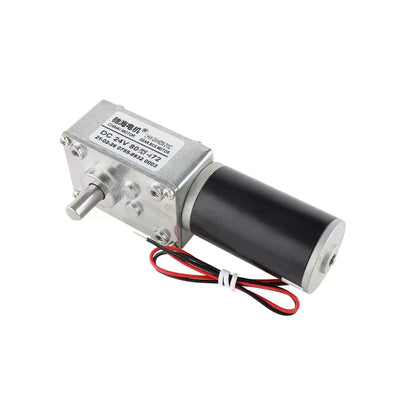
CHIHAI GM25-BLDC2418 Brushless DC Gear Motor, 6V / 12V / 24V
CHIHAI GM25-BLDC2418 Brushless DC Gear Motor, 6V / 12V / 24V
CHIHAI MOTOR
수령 가능 여부를 로드할 수 없습니다.


Overview
The CHIHAI MOTOR CHR-GM25-BLDC2418 is a compact 25 mm brushless DC gear motor with a built-in driver, all-metal reduction gears and a 4 mm D-shaped output shaft. Select the package, gear ratio and nominal voltage for your mechanism. PWM speed control, direction control and FG feedback support integration into small robots, electronic locks and automated equipment.
Features
- Brushless motor with integrated electronic drive.
- All-metal reduction gear train and D-shaped shaft for mechanical coupling.
- Separate CW/CCW, PWM and FG leads on a five-wire harness.
- Motor-only, bracket and speed-controller packages.
- Ten actual gear-ratio options, including 15:1.
Specifications
| Item | Specification |
|---|---|
| Model | CHR-GM25-BLDC2418 / GM25-BL2418 |
| Motor design | Permanent-magnet brushless DC gear motor, built-in driver, metal gears |
| Voltages | 6V black housing; 12V or 24V silver housing, as selected |
| Gearbox diameter | 25 mm |
| Motor can diameter | 24.4 mm |
| Output shaft | 4 mm D-shaft, 12 mm protrusion; flat length 8 mm |
| Shaft flat dimension | 3.5 mm |
| Front boss | 7 mm diameter; 2.5 mm projection |
| Motor can length | 18 mm, excluding gearbox and shaft |
| Mounting | Two M3 tapped holes on 17 mm spacing; check drawing before machining |
| Motor mass | Approximately 69 g; varies with gear ratio |
| Gear ratios offered | 4.4:1, 9.3:1, 15:1, 20:1, 34:1, 45:1, 75:1, 100:1, 125:1, 478:1 |
| Speed control | Active-low 0–5V PWM; typical 15–25 kHz, 60 kHz maximum |
| Direction control | CW/CCW logic input; high or open = CCW, low = CW |
| Feedback | FG motor-shaft pulses: 6 pulses/revolution for silver versions; 18 pulses/revolution for 6V black version |
| Connector | Five-position, 1.0 mm pitch connector shown; verify orientation against wiring diagram |
Performance by Voltage and Ratio
The following are series reference values at each stated voltage. Rated torque and stall torque are different limits. 15:1 is available, but its speed, torque and gearbox length are not specified in these tables. The 217:1 column is a series reference and is not a selectable option.
12V performance
Maximum power 0.65 W; no-load current ≤50 mA; rated current ≤0.13 A; stall current ≤0.35 A.
| Ratio | No-load rpm | Rated rpm | Rated torque (kgf·cm) | Stall torque (kgf·cm) |
|---|---|---|---|---|
| 4.4:1 | 1000 | 700 | 0.07 | ≥0.2 |
| 9.3:1 | 470 | 335 | 0.15 | ≥0.5 |
| 20:1 | 225 | 150 | 0.32 | ≥1.1 |
| 34:1 | 130 | 90 | 0.55 | ≥1.7 |
| 45:1 | 100 | 70 | 0.75 | ≥2.5 |
| 75:1 | 60 | 40 | 1.25 | ≥3.5 |
| 100:1 | 45 | 30 | 1.60 | ≥5.0 |
| 125:1 | 35 | 25 | 2.00 | ≥6.0 |
| 217:1 | 20 | 15 | 3.00 | ≥10.0 |
| 478:1 | 9.5 | 6 | 8.00 | ≥10.0 |
24V performance
Maximum power 2.5 W; no-load current ≤80 mA; rated current ≤0.26 A; stall current ≤0.65 A.
| Ratio | No-load rpm | Rated rpm | Rated torque (kgf·cm) | Stall torque (kgf·cm) |
|---|---|---|---|---|
| 4.4:1 | 2000 | 1450 | 0.15 | ≥0.4 |
| 9.3:1 | 960 | 700 | 0.30 | ≥1.0 |
| 20:1 | 450 | 325 | 0.65 | ≥2.2 |
| 34:1 | 260 | 190 | 1.10 | ≥3.5 |
| 45:1 | 200 | 145 | 1.50 | ≥5.0 |
| 75:1 | 120 | 85 | 2.50 | ≥7.0 |
| 100:1 | 90 | 65 | 3.30 | ≥10.0 |
| 125:1 | 72 | 52 | 4.00 | ≥10.0 |
| 217:1 | 41 | 30 | 6.00 | ≥10.0 |
| 478:1 | 19 | 12 | 8.00 | ≥10.0 |
6V performance
Maximum power 0.6 W; no-load current ≤170 mA; rated current ≤0.45 A; stall current ≤0.8 A.
| Ratio | No-load rpm | Rated rpm | Rated torque (kgf·cm) | Stall torque (kgf·cm) |
|---|---|---|---|---|
| 4.4:1 | 1360 | 840 | 0.07 | ≥0.2 |
| 9.3:1 | 645 | 400 | 0.15 | ≥0.5 |
| 20:1 | 300 | 185 | 0.32 | ≥1.1 |
| 34:1 | 175 | 108 | 0.55 | ≥1.7 |
| 45:1 | 133 | 82 | 0.75 | ≥2.5 |
| 75:1 | 80 | 50 | 1.25 | ≥3.5 |
| 100:1 | 60 | 37 | 1.60 | ≥5.0 |
| 125:1 | 48 | 30 | 2.00 | ≥6.0 |
| 217:1 | 27 | 17 | 3.00 | ≥10.0 |
| 478:1 | 12.5 | 7.7 | 8.00 | ≥10.0 |
Do not run stalled or repeatedly restart against a blocked load. One kgf·cm is a torque unit, not a supported payload in kilograms.
Mechanical Dimensions
| Gearbox length L | Series ratios |
|---|---|
| 19 mm | 4.4 / 9.3 / 20 |
| 21 mm | 34 / 45 |
| 23 mm | 75 / 100 |
| 25 mm | 125 / 217 (reference only) |
| 27 mm | 478 |
Use the drawing and actual selected motor to confirm mounting and shaft clearance before machining. No gearbox length is specified for 15:1.
Wiring and Control
6V black motors and 12V/24V silver motors use different pin assignments and wire colors. Never interchange their harness assumptions. Match the supply to the nominal voltage selected; do not reverse power polarity.
| Pin in drawing orientation | 12V/24V silver motor | 6V black motor |
|---|---|---|
| 1 | Blue — PWM | Black — GND |
| 2 | Black — GND | Red — VCC |
| 3 | Yellow — CW/CCW | Yellow — FG |
| 4 | Green — FG | White — PWM |
| 5 | Red — VCC | Orange — CW/CCW |
Direction logic accepts 0–5V: high (at least 2.0V) or open selects CCW; low (at most 0.5V) selects CW. PWM uses active-low operation: increasing the low-time proportion increases the run command. Silver-motor PWM high at least 2.0V or open stops the motor; low at most 0.5V runs. For the black 6V model, the signal table specifies at least 1.0V for stop and at most 0.5V for run. Typical PWM frequency is 15–25 kHz, maximum 60 kHz.
Silver-model FG output: 5.0V maximum high, 0.5V maximum low, 2mA signal current, 6 pulses per motor revolution. Black-model FG: 5.0V maximum high with 10 kΩ pull-up, 0.5V maximum low, 5mA signal current, 18 pulses per motor revolution. These are motor-shaft pulses, not output-shaft encoder counts. Motor speed in rpm can be calculated as 60 × frequency (Hz) ÷ pulses per motor revolution.
The 24V signal sheet lists nominal supply tolerance ±10%; this applies to the 24V motor only. The black model signal sheet shows a 5.5–10V input range, but the sold black configuration is nominal 6V: use 6V for the stated performance. An older summary lists 5–12V for the family; use the selected nominal voltage rather than applying that summary to all versions.
Optional Speed Controller
Packages listing a controller include one control board; the motor already contains its own driver. Connect controller supply V+/V− to the DC source and motor VCC/GND to red/black. Connect CW/CCW to yellow on silver motors or orange on black motors. For adjustable speed, connect controller PWM to blue on silver or white on black, leave BRAKE open, and leave FG unconnected to this controller. For brake-mode wiring, move the motor PWM wire to BRAKE and leave the controller PWM terminal open; speed adjustment is unavailable in that mode. Check terminal labels and the matching voltage diagram before applying power.
Applications
- Small robot drive and auxiliary mechanisms requiring geared rotary motion.
- Electronic lock and compact automation mechanisms.
- Automated rotating platforms and positioning mechanisms, with external control as required.
- Printer and appliance mechanism development where the selected motor ratings and dimensions fit.
Application photos illustrate possible integration contexts, not complete included systems or guaranteed drop-in compatibility.
What's Included
| Selected package | Contents |
|---|---|
| Motor Only | 1 selected geared motor with lead set |
| Motor + Mounting Bracket | 1 selected geared motor, 1 bracket |
| Motor + Speed Controller | 1 selected geared motor, 1 controller |
| Motor + Controller + Bracket | 1 selected geared motor, 1 controller, 1 bracket |
Package photographs illustrate the silver motor. The selected 6V option uses a black motor with its matching wiring. Power supply, robot, lock, printer and other application equipment are not included.
Installation and Operating Notes
- Select using rated torque, not stall torque; excessive load reduces speed and can damage the motor or gears.
- Reducing commanded speed can reduce available output torque; evaluate the load at the intended operating point.
- Noise varies with speed and load; no numeric acoustic rating is specified.
- Handle the connector body when disconnecting; do not pull on individual wires.
- Test wiring with suitable temporary leads before permanent installation.
FAQ
Can I use the same wiring for all voltages?
No. The black 6V version and silver 12V/24V versions have different pin assignments, PWM wire colors and FG pulse counts. Use the corresponding diagram.
Does Motor Only include the external speed controller?
No. Its driver is built into the motor, but the separate adjustment board is included only in controller packages.
What are the speed and torque of the 15:1 option?
Those values are not specified in the available performance table. Do not substitute the 20:1 or 9.3:1 figures when selecting it.
Is stall torque a continuous operating rating?
No. Select using rated torque and avoid blocked operation or repeated stalled starts.
Visual Details