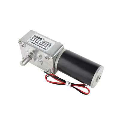
CHIHAI MOTOR GW4632-25BY Worm-Geared Stepper Motor
CHIHAI MOTOR GW4632-25BY Worm-Geared Stepper Motor
CHIHAI MOTOR
수령 가능 여부를 로드할 수 없습니다.


Overview
The CHIHAI MOTOR CHW-GW4632-25BY combines a two-phase stepper with a right-angle worm gearbox. This compact electric motor is available in seven reduction ratios and seven motor, bracket or driver packages. Choose the ratio for the required output step, speed and torque, then select the included control hardware.
Features
- Worm reduction with resistance to back-driving when unpowered, subject to the actual load and transmission conditions.
- 15° input motor step, with finer output steps through the selected reduction ratio.
- 6 mm D-shaped output shaft with an M3 center thread.
- Protected PCB wiring and a four-position motor connector.
- Optional mounting bracket and reciprocating drivers, including enclosed and external-control versions.
Specifications
| Specification | Value |
|---|---|
| Brand / model | CHIHAI MOTOR / CHW-GW4632-25BY |
| Motor construction | Two-phase bipolar stepper motor with right-angle worm reduction |
| Supply reference | 12V DC; L6219 driver reference |
| Input motor step | 15° per step |
| Phase resistance / inductance | 10 Ω ±7% / 7.5 mH per phase |
| Phase current / excitation | 300 mA per phase / two-phase excitation |
| Input pull-out torque | >60 gf·cm at 100 pulses/s |
| Input holding torque | >75 gf·cm at 0 pulses/s |
| Response / starting pulse rates | >1300 pulses/s response; >800 pulses/s starting |
| Winding insulation / dielectric test | Class E / 100V AC for one second |
| Insulation resistance test | 100 MΩ at 500V DC |
| Working temperature reference | −10 to +55°C |
| Motor weight | Approximately 135 g |
| Gearbox front / depth | 32 ×46 mm /25.2 mm |
| Overall motor assembly height | 61.0 mm reference |
| Output shaft | 6 mm diameter, tolerance +0/−0.03 mm; D-flat 5.4 mm +0/−0.1 mm |
| Shaft projection / flat length | 18.5 ±0.5 mm /12 mm |
| Shaft center thread | M3; maximum screw entry 4.0 mm |
| Gearbox mounting | Four M3 holes, 18 ×33 mm reference spacing |
| Other drawing references | 7.4 mm counterbore reference; shaft register 13.3 mm; front offset 1.7 mm; rear references 14.8, 0.5 and 3.7 mm; motor diameter 25 mm |
| Connector / lead | PHR-04 white; UL1571 AWG28; 150 ±10 mm lead |
| Connector pin sequence | Pin 1 yellow B+; pin 2 red B−; pin 3 black A+; pin 4 blue A− |
Reduction Ratio and Output Performance
The table is a 12V reference. No-load output speeds are specified at 700 input pulses/s. Holding and pull-out torque are different conditions, and neither establishes a continuous load rating. The 1019:1 row states a maximum permissible torque of 25 kgf·cm rather than a minimum performance guarantee.
| Reduction | Output step | No-load rpm at 700 pulses/s | Holding torque (kgf·cm) | Pull-out torque (kgf·cm) |
|---|---|---|---|---|
| 32:1 | 0.469° | 54 | ≥2.0 | ≥1.5 |
| 65:1 | 0.231° | 27 | ≥4.0 | ≥3.5 |
| 158:1 | 0.095° | 11 | ≥10.0 | ≥8.5 |
| 200:1 | 0.075° | 8.7 | ≥13.0 | ≥11.0 |
| 337:1 | 0.045° | 5.2 | ≥20.0 | ≥18.0 |
| 564:1 | 0.027° | 3.1 | ≥25.0 | ≥25.0 |
| 1019:1 | 0.015° | 1.72 | Maximum permitted 25 | Maximum permitted 25 |
Wiring and Control
Use a compatible two-phase bipolar stepper driver. Connect the yellow/red wires as phase B and the black/blue wires as phase A, following the connector pin order above and the motor drawing. Direction is determined by the excitation sequence; the drawing gives CW and CCW references viewed from the flange side.
The driver packages differ: the button-operated version provides reciprocating control, while the PLC-control version has additional external control terminals. Select the enclosed option when a housing is required. The motor's 12V reference does not establish every driver's input limits or PLC signal compatibility; confirm the actual board markings and interface before connection. Do not connect a bipolar stepper directly to a DC supply as though it were a two-wire brushed motor.
Mechanical Installation
Check shaft diameter, D-flat, projection, center-thread engagement and the gearbox hole pattern before fitting. Limit screw entry into the M3 shaft thread to 4.0 mm. Avoid forcing the output shaft or operating with a blocked shaft or overload. Evaluate back-driving resistance with the actual mechanism; power-off self-locking is not a substitute for an independently rated load restraint.
| Optional bracket | Drawing reference |
|---|---|
| Overall bracket | 46 mm high ×38 mm deep; 3 mm thickness |
| Upright hole pattern | 18 mm horizontal ×33 mm vertical; 3.3 mm holes with 7.8 mm counterbore references |
| Center apertures | 10 mm diameter; 15 mm spacing reference |
| Base slots | 18 mm length ×4.1 mm width; 32 mm spacing reference |
| Drawing offsets | 9, 6.5, 6.8 and 7 mm references; 30 mm inside height |
Flange Coupling Reference
The illustrated threaded flange coupling is a mechanical reference, separate from the current motor packages. It and the illustrated threaded rod are not included. Check thread and clearance dimensions if designing a similar mechanism.
| Reference accessory | Dimensions / scope |
|---|---|
| Status | Mechanical reference accessory; not included in current packages |
| Flange / mounting circle | 22 mm flange diameter; 16 mm mounting-hole center spacing |
| Flange holes | 4 ×3 mm diameter |
| Body dimensions | 12 mm overall length; 2 mm flange thickness; 10 mm body diameter |
| Thread / set screws | M6 ×1 axial thread; opposed M3 set screws; 8 mm drawing reference |
Applications
For compatible compact positioning mechanisms, balancing vehicles, inspection carts, home robots, camera-positioning assemblies and powered paper-folding mechanisms when the required step resolution, supply, load and mounting fit this motor.
What's Included
| Selected package | Contents |
|---|---|
| Motor Only | 1 motor |
| Motor + Mounting Bracket | 1 motor and 1 bracket |
| Motor + Reciprocating Driver | 1 motor and 1 button-operated reciprocating driver |
| Motor + PLC Reciprocating Driver | 1 motor and 1 driver with external/PLC control terminals |
| Motor + Bracket + PLC Reciprocating Driver | 1 motor, 1 bracket and 1 PLC-control driver |
| Motor + Enclosed Reciprocating Driver | 1 motor and 1 enclosed button-operated reciprocating driver |
| Motor + Enclosed PLC Reciprocating Driver | 1 motor and 1 enclosed driver with external/PLC control terminals |
Each selection includes one motor at the chosen reduction ratio. Brackets, drivers and housings are included only in the named package. A power supply, PLC, threaded rod and flange coupling are not included.
FAQ
Does the motor-only package include a driver?
No. It requires a compatible two-phase bipolar stepper driver. Choose a driver package if one is needed.
Are the listed speeds fixed output speeds?
No. They are no-load references at 700 input pulses/s and 12V. The selected ratio, pulse rate, driver and load affect operation.
Is the 1019:1 torque figure a minimum holding torque?
No. Its table specifies a maximum permissible torque of 25 kgf·cm. Do not treat it as a guaranteed minimum.
Does the motor include the threaded rod and flange coupling?
No. Those are reference accessories shown to explain the mechanical interface.
What is different about the PLC driver package?
It includes a driver with external control terminals. Check the actual terminal functions and electrical signal requirements against the intended PLC.
Visual Details