CHIHAI SP20-180 Mini Reciprocating Linear Actuator, 3.7V, 380/600 Cycles
CHIHAI SP20-180 Mini Reciprocating Linear Actuator, 3.7V, 380/600 Cycles
CHIHAI MOTOR
수령 가능 여부를 로드할 수 없습니다.


Overview
The CHIHAI MOTOR CHR-SP 20-180 is a compact reciprocating linear actuator driven by a 3.7 V brushed motor and reduction gears. Choose the actual 380 or 600 cycles-per-minute version and the required lead, bracket, controller or supply package. The dimensioned reference envelope is 77–85 mm, corresponding to approximately 8 mm travel.
Features
- Metal gear train, copper-wound rotor and carbon-brush construction.
- Compact plastic output mechanism with repeated linear travel.
- Two actual nominal reciprocating-speed choices.
- Matching bracket and controller packages for integration into small mechanisms.
Specifications
| Brand / model | CHIHAI MOTOR / CHR-SP 20-180 |
| Construction | Permanent-magnet brushed DC reciprocating geared motor, metal gears, copper windings and carbon brushes |
| Rated motor supply | 3.7 V DC |
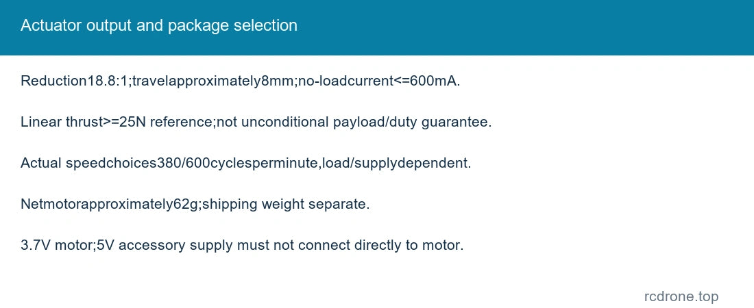
| Actual speed choices | 380 cycles/min or 600 cycles/min nominal no-load reciprocating choice; actual rate varies with supply and load |
| Referenced travel | Approximately 8 mm in the technical table and dimensioned 77–85 mm envelope; not a guaranteed 10 mm travel |
| Body diameter / length | 24.3 mm maximum output-body diameter; 77–85 mm overall reference envelope |
| Other drawing references | 22 mm/20 mm motor/body references; 32 mm motor can; 49.1 mm section; 7 mm output feature |
| Assembly reference | 18.8: 1 reduction; no-load current≤600 mA; linear thrust≥25 N reference under its stated test condition |
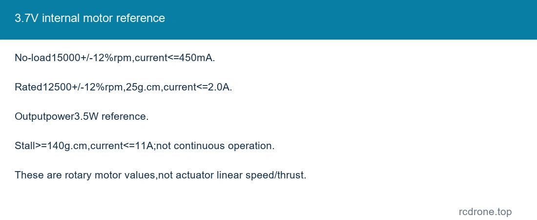
| Motor-only reference | 15000±12% rpm no-load at≤450 mA; 12500±12% rpm rated |
| Motor torque/current | Rated 25 g·cm at≤2.0 A; stall≥140 g·cm at≤11.0 A |
| Motor output power | 3.5 W reference; not a power guarantee at each package/speed/load |
| Net mass reference | Approximately 62 g excluding accessories and shipping packaging |
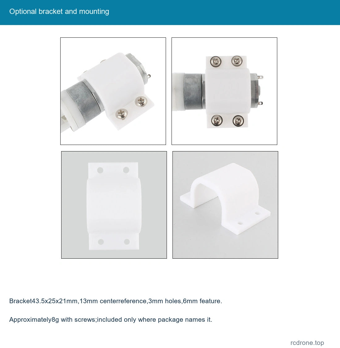
| Bracket | Approximately 43.5×25×21 mm; 13 mm hole-center reference, 3 mm holes, 6 mm feature; about 8 g with screws |
| Lead | Matching push-on terminal lead, approximately 280 mm reference, XH 2.54 two-pin style illustrated |
| Feedback / limits | No encoder, absolute position control or built-in limit-switch function specified |
Motor and Output References
Rotary motor rpm and g·cm are internal motor measurements, not linear output speed or thrust. The detailed electrical reference is for the CHR-SP 20-180 family at 3.7 V; it does not establish identical thrust, current or loaded cycle rate for both speed variants. Rated and stall values describe different conditions, and stall is not a continuous operating point.
Select by the actual 380 or 600 cycles/min option. Supply voltage, load, duty cycle and controller settings affect the real cycle rate. The technical drawing gives approximately 8 mm working travel; check the actual mechanism and clearances before designing a fixture.
Package Selection
| Actuator Only | One actuator plus only the named accessories |
| Actuator + Lead | One actuator plus only the named accessories |
| Actuator + Bracket | One actuator plus only the named accessories |
| Actuator + Bracket + Lead | One actuator plus only the named accessories |
| Actuator + Controller + Bracket | One actuator plus only the named accessories |
| Actuator + Controller + Lead + Bracket | One actuator plus only the named accessories |
| Actuator + 5V Supply + Controller + Lead | One actuator plus only the named accessories |
| Actuator + Supply + Controller + Lead + Bracket | One actuator plus only the named accessories |
A bracket and the pictured matching hardware are included only where named. A supply is included only in the two supply packages; the explicitly identified adapter is 5 V upstream of the controller. A controller does not by itself establish a new motor voltage rating. Do not connect a 5 V adapter directly to the 3.7 V motor; configure the supply/driver arrangement within the motor rated limits.
Connection and Mechanical Installation
Use a suitable DC motor driver and supply arrangement for the 3.7 V motor, with startup-current capacity and overcurrent protection. The motor-end illustration marks positive and negative terminals. Reverse the motor leads when a change of rotation is required, while keeping controller power-input polarity correct. Never connect household AC directly to the actuator or controller.
Connect the actuator to the controller motor output and the supply to its marked DC input. Inspect the actual board and adapter labels before connection. The knob adjusts the illustrated controller output setting; exact controller electrical ratings are not separately specified here.
Align the actuator and keep side loads off the moving output. Allow the entire 77–85 mm reference envelope, guard the moving end and avoid mechanical blocking or impact. Do not treat the actuator as a feedback-controlled positioning axis or a certified load-holding mechanism. Avoid prolonged stall, overheating and moisture.
Applications
Small reciprocating mechanisms, compact motion demonstrators and integration projects requiring repeated short linear travel. Validate actual thrust, speed, duty cycle and mounting for the application. General rotary load/lever illustrations do not establish a payload rating for this assembly.
What's Included
One selected SP 20-180 actuator and only the accessories named in the package. Power supply, bracket and controller are not universal inclusions. Complete equipment, external limit sensors, encoder, battery and extra loose internal components are not included.
FAQ
Is the rated motor voltage 5 V?
No. The motor reference is 3.7 V. A 5 V adapter in a package is an upstream accessory and must not be treated as a direct motor connection.
Is the travel exactly 10 mm?
The technical table and 77–85 mm dimension envelope give approximately 8 mm. Use this reference and check the actual assembly before fitting.
Does the 600 cycles/min option give the same loaded performance?
Not necessarily. Cycle rate, current and thrust depend on the selected version and operating conditions.
Does every option include a bracket?
No. Only packages explicitly naming a bracket include it.
Visual Details