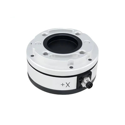
DECENT Y74 Six-Axis Force/Torque Sensor, 100–2000 N
DECENT Y74 Six-Axis Force/Torque Sensor, 100–2000 N
DECENT
수령 가능 여부를 로드할 수 없습니다.


Overview
The DECENT Y74 six-axis force/torque sensor measures three forces and three torques for robot contact feedback, machining tests and multi-axis research. A 17-4PH stainless-steel sensing body provides a compact, rigid load path between the equipment and tooling. Five sensor selections cover 100–2000 N, with separately selectable signal processors, a six-channel transmitter and a USB data adapter cable.
Features
- Fx, Fy, Fz and Tx, Ty, Tz measurement for multi-directional force control.
- 17-4PH stainless-steel construction with nominal Ø86 × 44.4 mm body dimensions.
- Calibrated, decoupled measurement with nonlinearity, hysteresis and repeatability each below 0.2% FS.
- 3 m sensor cable and flange interfaces for suitable robot/tool adapters.
- Optional DR304-A or DR304-B processing and recording equipment, sold as separate selections.
Specifications
| Sensor selection | Force / torque capacity |
|---|---|
| 100 N / 3 N·m sensor | 100 N / 3 N·m |
| 200 N / 6 N·m sensor | 200 N / 6 N·m |
| 500 N / 15 N·m sensor | 500 N / 15 N·m |
| 1000 N / 30 N·m sensor | 1000 N / 30 N·m |
| 2000 N / 60 N·m sensor | 2000 N / 60 N·m |
Capacity values above identify the individual selections. Assess the full combined-load envelope for your fixture, tool mass and dynamic forces before selecting a range.
| Measurement axes | Fx, Fy, Fz; Tx, Ty, Tz |
|---|---|
| Material | 17-4PH stainless steel |
| Nominal dimensions | Ø86 × 44.4 mm; use the drawing for hole patterns, tolerances and exact mounting surfaces |
| Sensor net mass | 1.2 kg; excludes shipping packaging |
| Maximum permissible overload | 500% FS; do not treat this as a normal working range |
| Cross-talk accuracy | 1% FS |
| Nonlinearity / hysteresis / repeatability / creep | Each <0.2% FS |
| Zero temperature drift | 0.1% FS / °C |
| Cross-axis coupling | <1% FS |
| Natural frequency | 5000 Hz |
| Stiffness | 500–600 N/µm |
| Inclination measurement | 0.1° resolution; 0.8° accuracy, for a compatible configuration |
| System interfaces | RS485, voltage output or EtherCAT, configuration dependent |
| System update rates | 40 / 1000 / 1000 Hz as associated with the respective interface configurations; processor software read rates are listed separately below |
| Communication protocols | Modbus RTU / DST-ASC, according to configuration |
| Sensor cable specification | Ø6 mm × 3 m |
| Cable tensile rating | 20 kg; provide strain relief and avoid loading the cable during use |
| Working supply | 10–30 VDC; <50 mA |
| Sensor ingress protection | IP64; the cable-entry illustration separately identifies an IP66 gland |
FS means full scale. Interface and inclination functions depend on the matched sensing and processing configuration; selecting a sensor does not include every interface or a separate processor.
Signal Processor Selection
| Selection / family reference | Functions | Software read rate |
|---|---|---|
| DR304-A | RS485 and TCP | 1000 Hz |
| DR304-B | RS485 and analog output (0 to ±10 V) | 10 Hz |
| 503 series | Six-channel transmitter; the 503B family reference has RS485 and optional EtherCAT / CANopen. The selected 503 configuration must be matched before integration. | 503B family reference: 10 Hz |
The D.R304 enclosure illustration identifies a sensor connector, power/RS485 terminal and Ethernet port, with 114 × 94 × 42 mm dimensions. Port availability and protocols follow the selected model. DR304-A lists one RS485-to-USB cable, one network cable and one software encryption key; DR304-B lists one RS485-to-USB cable. Optional EtherCAT and CANopen are not automatically included in the 503 selection. Software illustrations show real-time six-axis monitoring, traces, recording and Excel-compatible data export.
Applications
- Robot assembly, contact-force feedback and drag teaching.
- Machine-tool cutting, drilling, milling and sanding force tests.
- Rehabilitation equipment and research test fixtures.
- Flight-force measurement and materials research.
- Humanoid wrist and foot sensing with a suitable mechanical interface.
Installation and Cable Routing
Attach the base flange securely to the equipment and the tool to the designated tool side. In the illustrated coordinate frame, X points toward the cable outlet, Y is perpendicular to X, and Z points toward the tool. Positive torques follow the right-hand rule. Compensate for tool weight, orientation and inertia after installation.
The routing illustration shows a straight outlet section greater than 25 mm, static bend radius greater than 42 mm and dynamic bend radius greater than 84 mm for its illustrated 8.4 mm cable. The Y74 specification table identifies a 6 mm cable; match routing limits to the cable actually fitted. Secure the outlet, allow movement slack and avoid sharp bends. Adapter diagrams illustrate installation examples; bolt sizes and torque depend on the actual fixture.
What's Included
- Sensor selection: 1 × Y74 six-axis force/torque sensor in the selected range, with its 3 m cable.
- DR304-A / DR304-B: 1 × selected signal processor only; sensor not included.
- 503 six-channel transmitter: 1 × transmitter only; sensor not included.
- USB data adapter cable: 1 × selected cable only.
Robot arms, tools, application equipment and custom adapter flanges are not included. Family, packaging and hardware illustrations do not add accessories to a sensor-only selection.
Visual Details