Kunwei Sensing KWR75 Six-Axis Force/Torque Sensor, 75 mm, 1000 Hz for Robotic Force Measurement
Kunwei Sensing KWR75 Six-Axis Force/Torque Sensor, 75 mm, 1000 Hz for Robotic Force Measurement
Kunwei Sensing
수령 가능 여부를 로드할 수 없습니다.


Overview
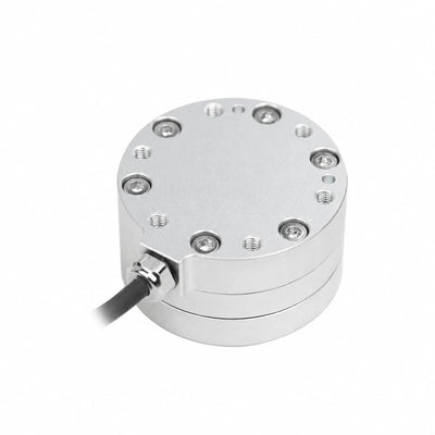
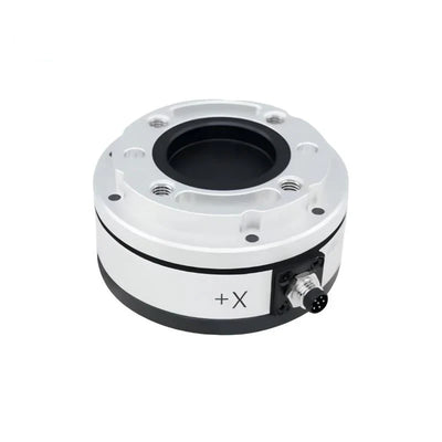
The Kunwei Sensing KWR75 is an embedded six-axis force/torque sensor for robotic force measurement, drag teaching, assembly and load testing. Its 75 mm diameter, digital output and 1000 Hz sampling frequency support integration into force-monitoring systems. Eight versions offer different force and torque ranges, with heights of 31.5 or 33.5 mm. All versions operate from a 12–48 VDC supply.
Features
- Measures force on Fx, Fy and Fz and torque on Mx, My and Mz.
- Silicon strain-gauge sensing uses strain-based electrical measurement to convert applied load into a voltage signal.
- Six-axis joint calibration technology and digital signal output.
- Aluminum-alloy construction with version-specific anodized or electropolished surface treatment.
- Eight selectable versions: KWR75A, KWR75B, KWR75C, KWR75D, KWR75E, KWR75F, KWR75G and KWR75K.
Specifications
Version Specifications
| Parameter | Unit | KWR75A | KWR75B | KWR75C | KWR75D | KWR75E | KWR75F | KWR75G | KWR75K |
|---|---|---|---|---|---|---|---|---|---|
| Range Fx, Fy | N | 50 | 200 | — | 500 | 30 | 100 | 800 | 1800 |
| Range Fz | N | 50 | 200 | 500 | 700 | 30 | 100 | 1000 | 3000 |
| Range Mx, My | N·m | 2 | 8 | 12 | 18 | 1.5 | 4 | 36 | 45 |
| Range Mz | N·m | 2 | 8 | 12 | 18 | 1.5 | 4 | 36 | 45 |
| Diameter | mm | 75 | 75 | 75 | 75 | 75 | 75 | 75 | 75 |
| Height | mm | 31.5 | 31.5 | 33.5 | 33.5 | 31.5 | 31.5 | 33.5 | 33.5 |
| Material | — | Aluminum alloy | Aluminum alloy | Aluminum alloy | Aluminum alloy | Aluminum alloy | Aluminum alloy | Aluminum alloy | Aluminum alloy |
| Surface treatment | — | Anodized | Anodized | Anodized | Anodized | Anodized | Anodized | Electropolished | Electropolished |
| Overload level | %FS | 300 | 300 | 300 | 300 | 300 | 300 | 300 | 200 |
| Resolution | %FS | 0.03 | 0.03 | 0.03 | 0.03 | 0.03 | 0.03 | 0.03 | 0.03 |
| Repeatability | %FS | 0.1 | 0.1 | 0.1 | 0.1 | 0.1 | 0.1 | 0.1 | 0.5 |
| Accuracy | %FS | 0.5 | 0.5 | 0.5 | 0.5 | 0.5 | 0.5 | 0.5 | 2 |
| Weight | kg | 0.08 | 0.28 | 0.32 | 0.36 | 0.26 | 0.28 | 1.1 | 1.12 |
| Protection level | — | IP64 | IP64 | IP64 | IP64 | IP64 | IP63 | IP64 | IP64 |
| Working temperature | °C | −10 to 80 | −10 to 80 | −10 to 80 | −10 to 80 | −10 to 80 | −10 to 80 | −10 to 80 | −10 to 80 |
| Sampling frequency | Hz | 1000 | 1000 | 1000 | 1000 | 1000 | 1000 | 1000 | 1000 |
| Supply voltage | VDC | 12–48 | 12–48 | 12–48 | 12–48 | 12–48 | 12–48 | 12–48 | 12–48 |
FS means full scale. The dash in the KWR75C Fx/Fy cell indicates that a confirmed value is not available.
Signal and Communications
| Scope | Signal or communications |
|---|---|
| KWR75 series | Digital signal output |
| KWR75 series; individual version assignment unspecified | RS422, RS485, MODBUS and Industrial Ethernet Protocol |
| KWR75A–KWR75F; individual protocol assignment unspecified | RS422, RS485, Modbus-RTU and CAN |
Mechanical Reference Dimensions
The following mounting dimensions are KWR75 mechanical reference dimensions. Parenthesized dimensions are retained as alternatives without assigning them to individual versions.
| Area | Detail | Dimension or tolerance |
|---|---|---|
| Body | Outside diameter | Ø75 mm |
| Tool side | Pin holes | 2 × Ø6 mm; diameter tolerance +0.02/0 mm; depth 6 mm |
| Tool side | Threaded holes | 4 × M6; depth 6 mm |
| Tool side | Hole-pattern diameters | Ø50 mm and Ø63 mm |
| Tool side | Angular offsets from Y+ centerline | 2 × 45° |
| Tool side | Offsets from X+ centerline | 25 mm above and 25 mm below |
| Tool side | Positional tolerance | 0.02 mm relative to datum A |
| Section A–A | Screw designation and section dimension | M4 hexagon socket cap screws; 5 mm dimension |
| Mounting side | Hole-pattern diameter | Ø66 ±0.05 mm |
| Mounting side | Pin holes | 2 × Ø5 mm; diameter tolerance +0.02/0 mm; depth 6 mm |
| Mounting side | Pin-hole positional tolerance | 0.02 mm relative to datum A |
| Mounting side | Angular intervals | 6 × 20° |
| Mounting side | Angular dimensions | 2 × 120° ±0.03° |
| Lower section | Diameter | Ø31.5 mm; tolerance +0.03/0 mm |
| Lower section | Section height | 24.5 mm (26.5 mm) |
| Lower section | Overall height | 31.5 mm (33.5 mm) |
Applications
- Robotic drag teaching and precision assembly: Measure forces and torques during hand-guided motion and component insertion with robotic arms and collaborative robots. Six-axis sensing supports monitoring contact loads during tasks such as automobile gearbox assembly.
- Curved-surface grinding and precision polishing: Monitor tool-to-workpiece forces and torques during surface finishing to provide load feedback for the process.
- Cutting-force measurement and torque monitoring: Capture loads on three force axes and three torque axes for machining, 3C testing and automobile testing.
- Collaborative-robot collision testing: Record contact forces and moments during controlled collision tests using the 1000 Hz sampling frequency.
- Robotic vehicle-charging engagement: Monitor contact loads while positioning a charging connector for a new-energy vehicle.
- Robot interaction and mobility testing: Measure interaction loads during development of humanoid robots, quadruped robots and AGV systems.
- Exoskeleton, motion-rehabilitation and sport-performance testing: Measure applied forces and torques during assisted-motion and performance test tasks.
- Medical detection, medical testing and surgical-robot development: Provide force/torque measurements for instrumented testing and robot interaction studies.
Documents and Downloads
- KUNWEI KWR75 Drawing Series — Drawing (PDF)
- Kunwei KWR63 Series RS485 — User Manual (PDF)
- KUNWEI KWR75 CAN — User Manual (PDF)
- KUNWEI KWR75 CAN — User Manual (PDF)
- KUNWEI KWR75 EtherCAT — User Manual (PDF)
- KUNWEI KWR75 CAN — User Manual (PDF)
- KUNWEI KWR75 RS422 — User Manual (PDF)
- KUNWEI KWR75 CAN — User Manual (PDF)
- KUNWEI KWR75 RS485 — User Manual (PDF)
- KUNWEI 6 Axis Force Sensors Selection — Manual (PDF)
FAQ
Do all KWR75 versions have the same dimensions?
All eight versions have a 75 mm diameter. KWR75A, KWR75B, KWR75E and KWR75F are 31.5 mm high; KWR75C, KWR75D, KWR75G and KWR75K are 33.5 mm high.
Do all versions have the same accuracy and protection level?
No. KWR75A–KWR75G have 0.5%FS accuracy and 0.1%FS repeatability; KWR75K has 2%FS accuracy and 0.5%FS repeatability. KWR75F is rated IP63, while the other seven versions are rated IP64.
What power supply and sampling frequency does the sensor use?
Every listed version uses a 12–48 VDC supply and has a 1000 Hz sampling frequency.
Visual Details
Specifications and Performance

Dimensions and Construction

Application Examples