Yahboom STM32 Zelfbalancerende Robotauto Kit, 4KG Draagvermogen, STM32F103RCT6, 6-assige IMU, OLED, BT 5.0
Yahboom STM32 Zelfbalancerende Robotauto Kit, 4KG Draagvermogen, STM32F103RCT6, 6-assige IMU, OLED, BT 5.0
Yahboom
Kan beschikbaarheid voor afhalen niet laden
Overzicht
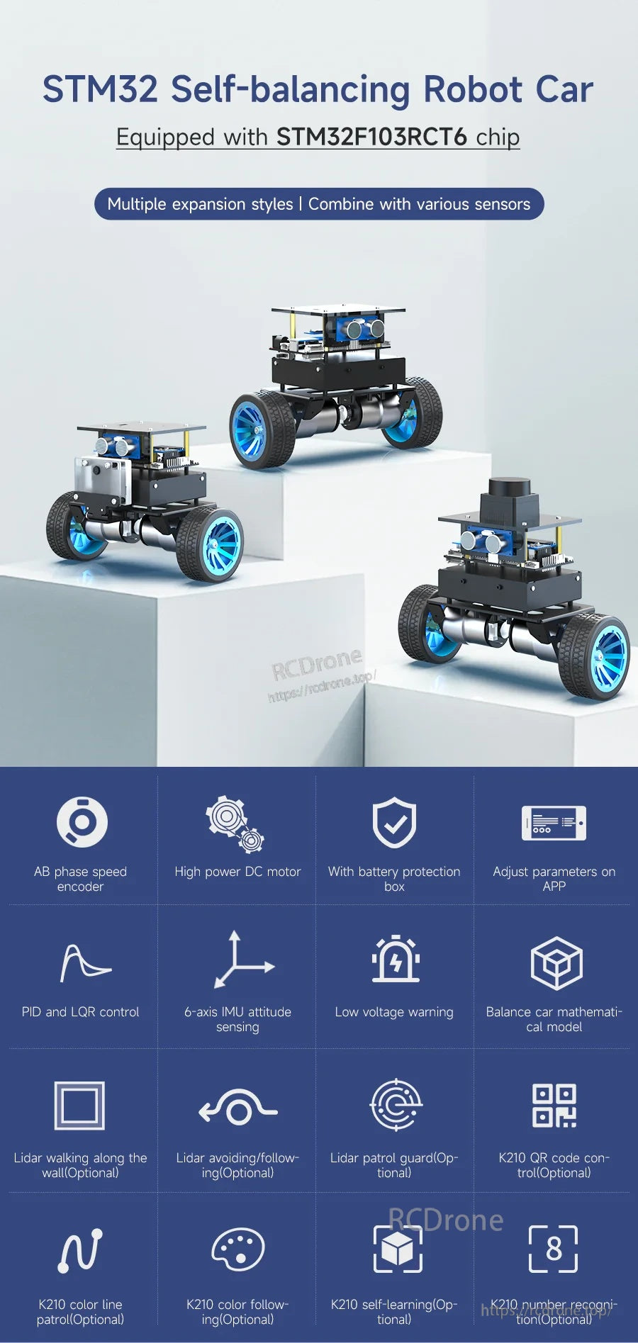
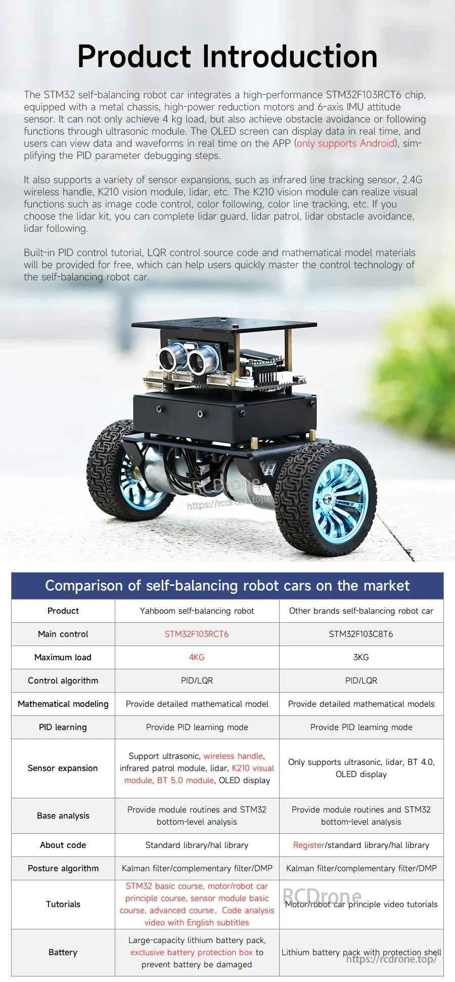
De STM32 zelfbalancerende robotauto is een leer- en experimenteerplatform voor robotauto's gebaseerd op de STM32-microcontroller voor verkenning van robotica en regelsystemen. Het integreert een STM32F103RCT6 hoofdcontrole, een 6-assige IMU-houdingssensor (versnellingsmeter + gyroscoop), krachtige reductiemotoren en een metalen chassis, waardoor realtime kantelwaarneming en balansstabilisatie mogelijk zijn met behulp van PID-regeling. Het platform ondersteunt een maximale belasting van 4KG en biedt een OLED-display plus een mobiele APP voor debugging en controle (ondersteunt alleen Android, niet iOS). Meerdere uitbreidingsstijlen worden ondersteund om te combineren met verschillende sensoren.
Belangrijkste Kenmerken
- Uitgerust met STM32F103RCT6-chip
- AB-fase snelheidsencoder
- Hoogvermogen DC-motor
- Met batterijbeschermingsbox
- Parameters aanpassen via APP
- PID- en LQR-regeling
- 6-assige IMU-houdingsdetectie
- Laagspanningswaarschuwing
- Wiskundig model van balansvoertuig
- Ultrasone vermijdings-/volgfuncties (via ultrasoon module)
- OLED-gegevensweergave (ondersteunt weergave van huidige modus en spanning)
- Houdingsherkenning (6-assige IMU kan balans starten wanneer op de grond geplaatst; kan balans uitschakelen wanneer verticaal in een rechtopstaande positie opgetild)
- Klimvermogen: hellingen van ongeveer 30°
Optionele uitbreidingsfuncties (afhankelijk van kit/modules)
- Lidar langs de muur lopen (Optioneel)
- Lidar vermijden/volgen (Optioneel)
- Lidar bewaking (Optioneel)
- K210 QR-code besturing (Optioneel)
- K210 kleur lijnpatrouille (Optioneel)
- K210 kleur volgen (Optioneel)
- K210 zelflerend (Optioneel)
- K210 nummerherkenning (Optioneel)
Specificaties
Hoofdcontroller (MCU)
| Model | STM32F103RCT6 |
| Kern | Cortex M3 R1P1 |
| Interne Flash | 256KB |
| SRAM | 48KB |
| GPIO aantal | 51 |
| Timer | 8 |
| Pakket pinnen | LQFP64 |
| Interfacebronnen | 2 x SPI, 3 x USART, 2 x I2C, 2 x I2S, 1 x CAN, 51 x I/O, 2 x DAC |
| Spanningsbereik | Externe spanning: 2.0~3.6V; Kernspanning: 1.8V |
| Compilatiehulpmiddel | KEIL MDK, STM32CubeMX |
STM32F103RCT6 wordt beschreven als een high-performance 32-bit MCU met tot 256KB Flash en 48KB SRAM, die 51 programmeerbare in-/uitgangspinnen biedt voor complexe toepassingen zoals robotsystemen en zelfbalancerende robotautobesturingssystemen.
Chassis
| Metaalplaatdikte | 2mm |
| Oppervlak | Geschilderd en mat oppervlak |
| Aandrijving | Hoogvermogen reductiemotor met AB-fase encoder |
Motorparameters
| Motormodel | MD520Z30_12V |
| Nominale motortspanning | 12V |
| Motortype | Permanente magneetborstel |
| Uitgaande as | D-type excentrische as met 6mm diameter |
| Nominaal vermogen | <=4W |
| Nominale stroom | 0.3A |
| Vertragingsverhouding tandwielset | 1:30 |
| Snelheid voor vertraging | 11000rpm |
| Snelheid na vertraging | 333±10rpm |
| Blokkeerkoppel | 4.8kg·cm |
| Nominaal koppel | 3.3kg·cm |
| Blokkeerstroom | 3A |
| Interface type | PH2.0 6Pin |
| Enkel motorgewicht | 150g±1g |
| Functie | Ingebouwde pull-up shaping, de microcontroller kan direct de signaalpuls lezen |
Encoder parameters
| Encoder type | AB fase incrementele Hall-encoder |
| Encoder lijnnummer | 11ppr |
| Type | Magnetische inductie |
| Voedingsbereik | 3.3V~5V |
| Encoderbescherming | Exposed (magnetische encoder is stabieler en vereist geen achterklep) |
| Geschikte MCU | Bijna alle microcontrollers |
Laadcapaciteit
| Maximale belasting | 4KG |
Controle & houding algoritmen (zoals geleverd)
- Controle algoritme: PID/LQR
- Houding algoritme: Kalman-filter / complementair filter / DMP
Encoder motor bedrading (PH2.0 6Pin)
| 1 | Motor voedingslijn + |
| 2 | Motor voedingslijn - |
| 3 | Sensor signaal-negatief |
| 4 | Sensor signaal-positief 3.3V |
| 5 | Sensor signaallijn-B fase |
| 6 | Sensor signaallijn-A fase |
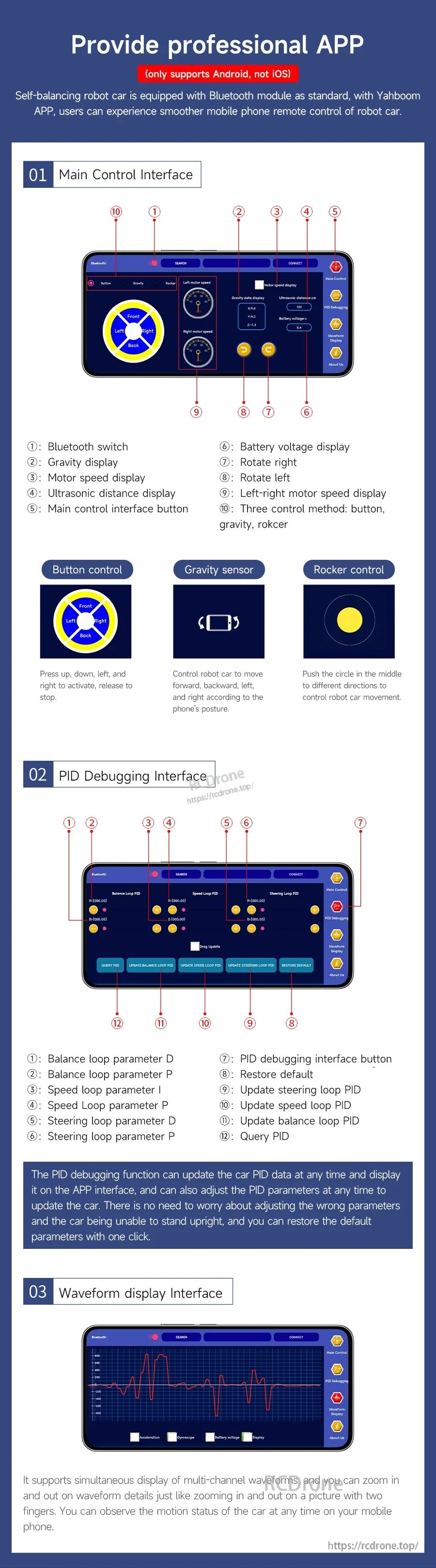
APP-besturing (alleen Android)
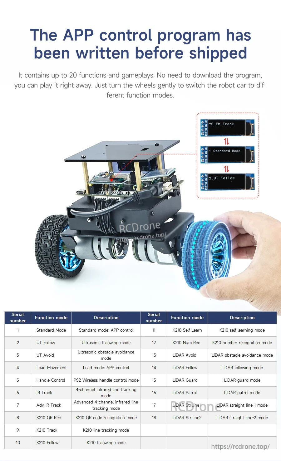
Het APP-besturingsprogramma is vooraf geïnstalleerd. Het bevat tot 20 functies en spelmogelijkheden. Het programma hoeft niet te worden gedownload; het kan direct worden gebruikt. Draai de wielen voorzichtig om de robotauto naar verschillende functiemodi te schakelen.
Hoofdcontrole-interface (labels)
- Bluetooth-schakelaar
- Zwaartekrachtweergave
- Motorsnelheidsweergave
- Ultrasone afstandsweergave
- Hoofdcontrole-interfaceknop
- Accuspanningsweergave
- Draai naar rechts
- Draai naar links
- Links-rechts motorsnelheidsweergave
- Drie bedieningsmethoden: knop, zwaartekracht, joystick
- Knopbediening: Druk op omhoog, omlaag, links en rechts om te activeren, laat los om te stoppen.
- Gravitatie sensor: Bestuur de robotauto om vooruit, achteruit, links en rechts te bewegen volgens de houding van de telefoon.
- Rockerbesturing: Duw de cirkel in het midden naar verschillende richtingen om de beweging van de robotauto te besturen.
PID-debuginterface (labels)
- Balanslusparameter D
- Balanslusparameter P
- Snelheidslusparameter I
- Snelheidslusparameter P
- Stuurloopparameter D
- Stuurloopparameter P
- PID-debuginterfaceknop
- Herstel standaard
- Update stuurloop PID
- Update snelheidslus PID
- Update balanslus PID
- PID opvragen
De PID-debugfunctie kan de auto PID-gegevens bijwerken en weergeven op de APP-interface, en kan ook de PID-parameters aanpassen en de standaardparameters met één klik herstellen.
Golfvorm weergave-interface
Ondersteunt gelijktijdige weergave van golfvormen van meerdere kanalen. Details van de golfvorm kunnen worden in- en uitgezoomd, en de bewegingsstatus van de robotauto kan op een mobiele telefoon worden geobserveerd.
Functiemodi lijst (zoals verstrekt)
| Serienummer | Functiemodus | Beschrijving |
|---|---|---|
| 1 | Standaardmodus | Standaardmodus: APP-besturing |
| 2 | UT Volgen | Ultrasone volgmodus |
| 3 | UT Vermijden | Ultrasone obstakelvermijdingsmodus |
| 4 | Laadbeweging | Laadmodus: APP-besturing |
| 5 | Handgreepbesturing | PS2 draadloze handgreepbesturingsmodus |
| 6 | IR Volg | 4-kanaals infrarood lijnvolgmodus |
| 7 | Geavanceerde IR Volg | Geavanceerde 4-kanaals infrarood lijnvolgmodus |
| 8 | K210 QR Herkenning | K210 QR-code herkenningsmodus |
| 9 | K210 Track | K210 lijnvolgmodus |
| 10 | K210 Follow | K210 volgmodus |
| 11 | K210 Self Learn | K210 zelflerende modus |
| 12 | K210 Num Rec | K210 nummerherkenningsmodus |
| 13 | LiDAR Avoid | LiDAR obstakelvermijdingsmodus |
| 14 | LiDAR Follow | LiDAR volgmodus |
| 15 | LiDAR Guard | LiDAR bewakingsmodus |
| 16 | LiDAR Patrol | LiDAR patrouillemodus |
| 17 | LiDAR StrLine1 | LiDAR rechte lijn-1 modus |
| 18 | LiDAR StrLine2 | LiDAR rechte lijn-2 modus |
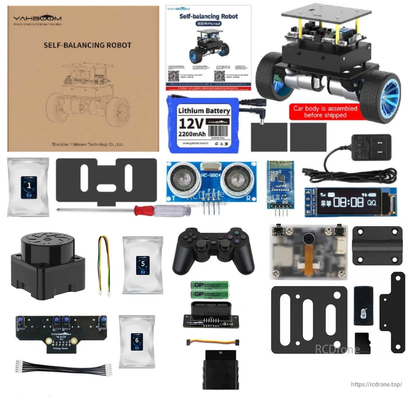
Wat is inbegrepen
Verschillende kits zijn beschikbaar. De volgende kitinhoud wordt geleverd zoals vermeld.
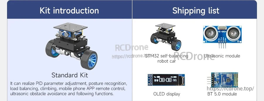
Standaard Kit
- STM32 zelfbalancerende robotauto
- Ultrasoon module
- OLED-display
- BT 5.0 module
Beschrijving van de functies van de Standaard Kit: PID-parameterafstelling, houdingsherkenning, belastingbalancering, klimmen, mobiele telefoon APP-afstandsbediening, ultrasone obstakelvermijding en volgfuncties.
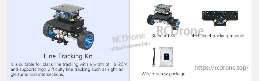
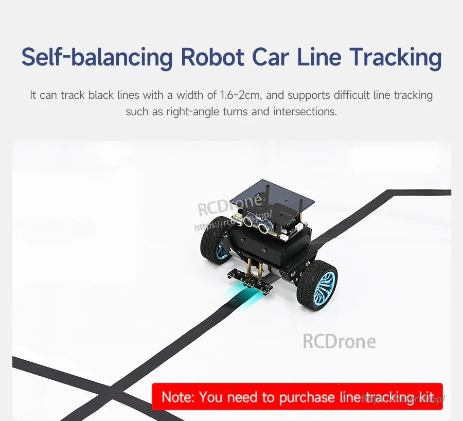
Lijnvolgkit
- Standaard Kit
- 4-kanaals volgmodule
- Draad + schroefpakket
Opmerkingen bij de Lijnvolgkit: Geschikt voor het volgen van zwarte lijnen met een breedte van 1,6~2CM, en ondersteunt lijnvolgen met hoge moeilijkheidsgraad zoals haakse bochten en kruispunten.
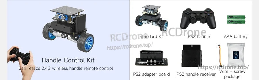
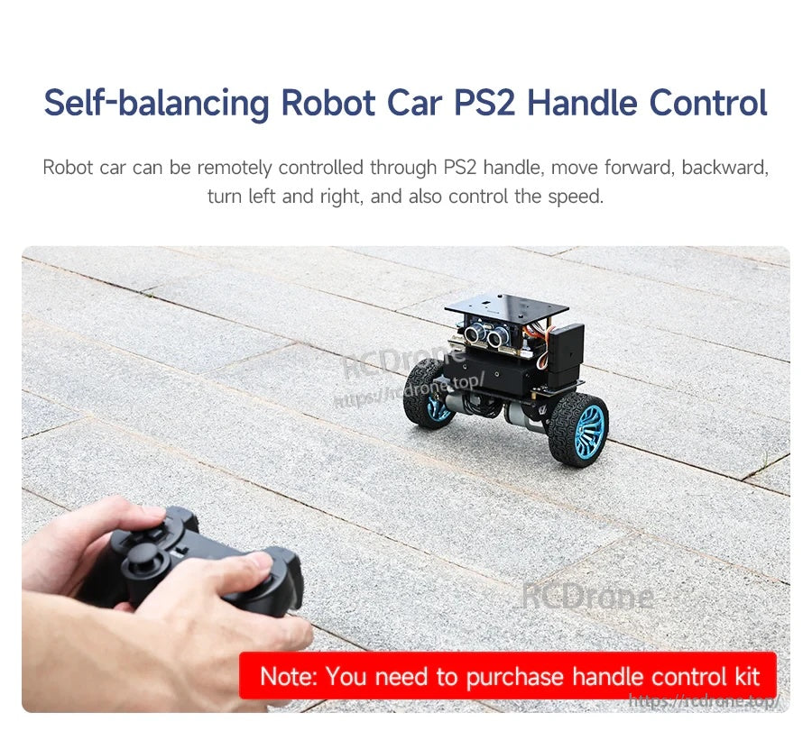
Handle Control Kit
- Standaard Kit
- PS2-handvat
- AAA-batterij
- PS2-adapterbord
- PS2-handvatontvanger
- Draad + schroefpakket
Handle Control Kit-opmerkingen: Kan 2.4G draadloze handvat afstandsbediening realiseren.
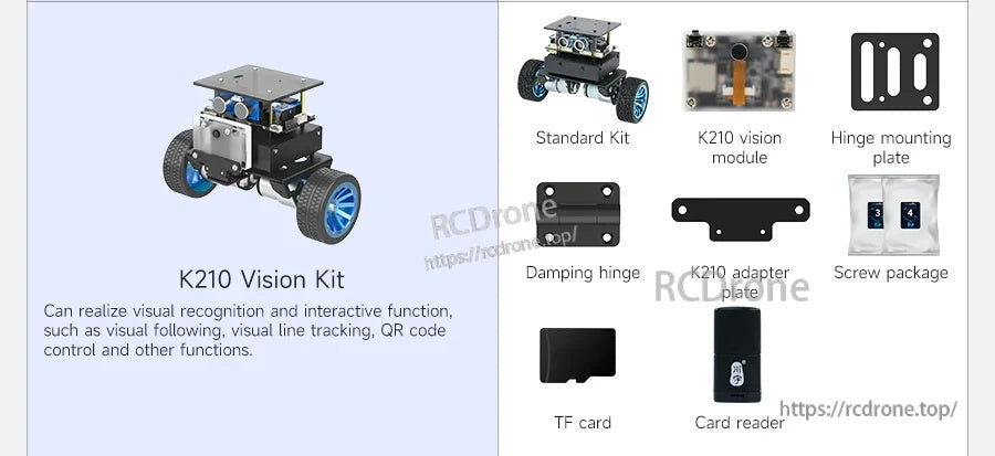
K210 Vision Kit
- Standaard Kit
- K210 vision module
- Scharnier montageplaat
- Dempend scharnierplaat
- K210-adapter
- Schroefpakket
- TF-kaart
- Kaartlezer
K210 Vision Kit-opmerkingen: Kan visuele herkenning en interactieve functies realiseren zoals visueel volgen, visuele lijntracking, QR-codebesturing en andere functies.
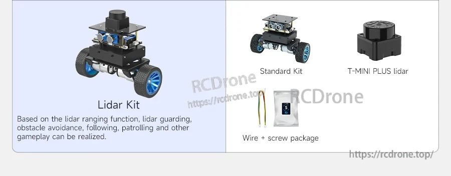
Lidar Kit
- Standaard Kit
- T-MINI PLUS lidar
- Draad + schroefpakket
Lidar Kit opmerkingen: Op basis van lidar-afstandsfuncties kunnen lidar-bewaking, obstakelvermijding, volgen, patrouilleren en andere gameplay worden gerealiseerd.
Voor hulp bij het kiezen van de juiste kit en accessoires, neem contact op [email protected] or bezoek https://rcdrone.top/.
Toepassingen
- Robotica-educatie en klaslokaaldemonstraties
- Leerproces voor regelalgoritmen (PID / LQR) en parameterdebugging
- Sensoruitbreidingsexperimenten (ultrasoon, infraroodlijnvolging, 2.4G draadloze bediening, K210 vision module, lidar)
Handleidingen
Handleiding link
STM32 Zelfbalancerende Robotauto
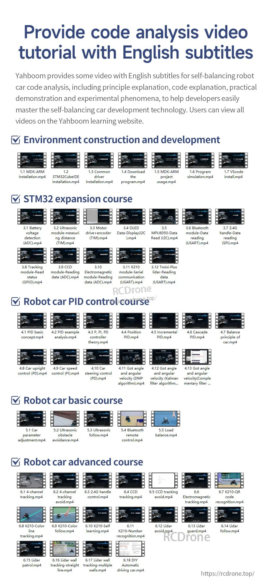
Code analyse videotutorial met Engelse ondertitels (zoals vermeld)
-
Omgevingsconstructie en ontwikkeling
- 1.1 MDK-ARM installation.mp4
- 1.2 STM32CubeIDE installation.mp4
- 1.3 Algemene driver installation.mp4
- 1.4 Download de program.mp4
- 1.5 MDK-ARM project usage.mp4
- 1.6 Programma simulation.mp4
- 1.7 VSCode install.mp4
-
STM32 uitbreidingscursus
- 3.1 Batterijspanningsdetectie (ADC).mp4
- 3.2 Ultrasoon module-afstand meten (TIM).mp4
- 3.3 Motorsturing+encoder (TIM).mp4
- 3.4 OLED Gegevensweergave (I2C).mp4
- 3.5 MPU6050-Gegevens lezen (I2C).mp4
- 3.6 Bluetooth-module-Gegevens lezen (USART).mp4
- 3.7 2.4G handgreep-besturingsmodule lezen (SPI).mp4
- 3.8 Volgmodule-Status lezen (GPIO).mp4
- 3.9 CCD-module-Gegevens lezen (ADC).mp4
- 3.10 Elektromagnetische module-Gegevens lezen (ADC).mp4
- 3.11 K210-module-Seriële communicatie (USART).mp4
- 3.12 Tmini-Plus lidar-Gegevens lezen (USART).mp4
-
Robotauto PID-regelcursus
- 4.1 PID basis concept.mp4
- 4.2 PID voorbeeld analysis.mp4
- 4.3 P, PI, PD regelaar theory.mp4
- 4.4 Positie PID.mp4
- 4.5 Incrementeel PID.mp4
- 4.6 Cascade PID.mp4
- 4.7 Balansprincipe van car.mp4
- 4.8 Auto rechtop controle (PD).mp4
- 4.9 Autosnelheidscontrole (PI).mp4
- 4.10 Autostuurcontrole (PD).mp4
- 4.11 Hoek en hoeksnelheid verkregen (DMP-algoritme).mp4
- 4.12 Hoek en hoeksnelheid verkregen (Kalman-filteralgoritme).mp4
- 4.13 Hoek en hoeksnelheid verkregen (Complementaire filter ...)
-
Robotauto basiscursus
- 5.1 Auto parameter adjustment.mp4
- 5.2 Ultrasone obstakel avoidance.mp4
- 5.3 Ultrasoon follow.mp4
- 5.4 Bluetooth afstandsbediening control.mp4
- 5.5 Belasting balance.mp4
-
Robotauto gevorderde cursus
- 6.1 4-kanaals tracking.mp4
- 6.2 4-kanaals tracking avoid.mp4
- 6.3 2.4G handvat control.mp4
- 6.4 CCD tracking.mp4
- 6.5 CCD tracking avoid.mp4
- 6.6 Elektromagnetisch tracking.mp4
- 6.7 K210-QR code recognition.mp4
- 6.8 K210-Kleurlijn tracking.mp4
- 6.9 K210-Kleur follow.mp4
- 6.10 K210-Zelf learning.mp4
- 6.11 K210-Nummer recognition.mp4
- 6.12 Lidar avoid.mp4
- 6.13 Lidar guard.mp4
- 6.14 Lidar follow.mp4
- 6.15 Lidar patrol.mp4
- 6.16 Lidar muurvolging-rechtdoor line.mp4
- 6.17 Lidar muurvolging-meerdere walls.mp4
- 6.18 Doe-het-zelf Automatisch rijden car.mp4
Details
Een compacte STM32-gebaseerde zelfbalancerende robotplatform ontworpen voor het leren van regelsystemen, afstemming en sensorenuitbreiding.
Een overzicht van de besturingshardware van het platform, sensoren en kernbalanceringsfuncties, plus een marktvergelijking voor snelle selectie.
Stapsgewijze leermiddelen behandelen de installatie van de omgeving, uitbreidingslessen, PID-afstemming en progressieve robotcursussen.

Kies de standaardkit voor kernbalancering plus ultrasone functies en statusweergave op het apparaat.
Voeg de lijnvolgkit toe om zwarte tape-routes te volgen en haakse bochten en kruispunten te hanteren.
De handgreepbedieningskit maakt draadloos PS2-stijl rijden en snelheidsregeling mogelijk.
De K210 vision kit opent AI-stijl interacties zoals QR-besturing, kleurtracking en visueel volgen.
Upgrade naar lidar voor geavanceerde navigatiegedragingen zoals volgen, obstakelvermijding en bewakingsmodi.
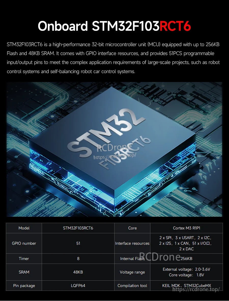
Gebouwd rond een STM32F103RCT6 MCU om real-time balanscontrole en rijke perifere uitbreiding te ondersteunen.
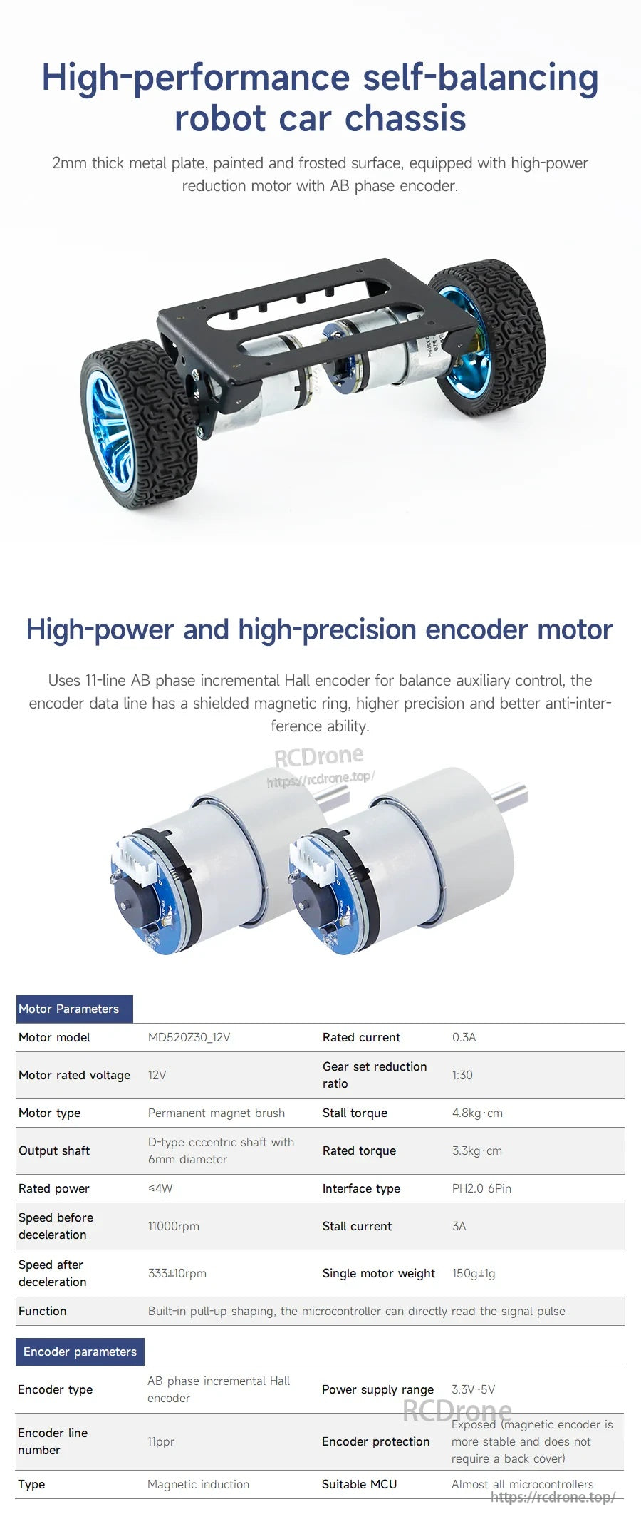
Een stevig metalen chassis en encodermotoren bieden stabiele feedback voor balanscontrole en snelheidsmeting.

Details over de motorconstructie en bedrading bieden hulp bij montage, probleemoplossing en controle-experimenten.
Een Android-app ondersteunt parameterinstelling en schakelen tussen meerdere bewegings- en sensormodi.
Besturing, PID-afstemming en golfvormvisualisatie zijn georganiseerd in speciale app-schermen voor snellere foutopsporing.

Kernfuncties omvatten houdingsherkenning, een draagvermogen tot 4 kg, klimvermogen, ultrasone vermijding en OLED-weergaven.
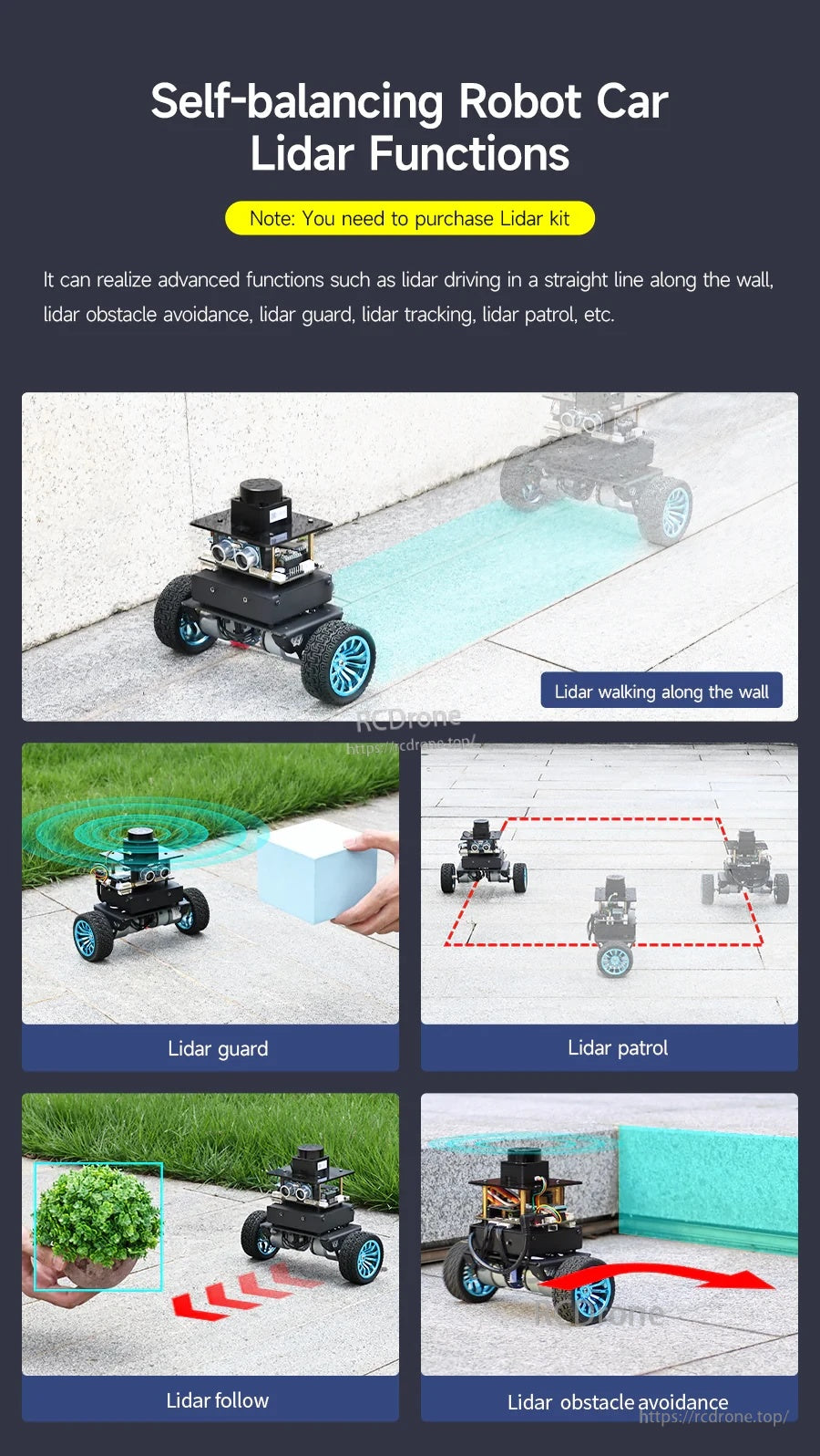
De Yahboom STM32 zelfbalancerende robotauto ondersteunt LiDAR-gebaseerd muurvolgen, obstakelvermijding, patrouilleren, bewaken en volgfuncties.
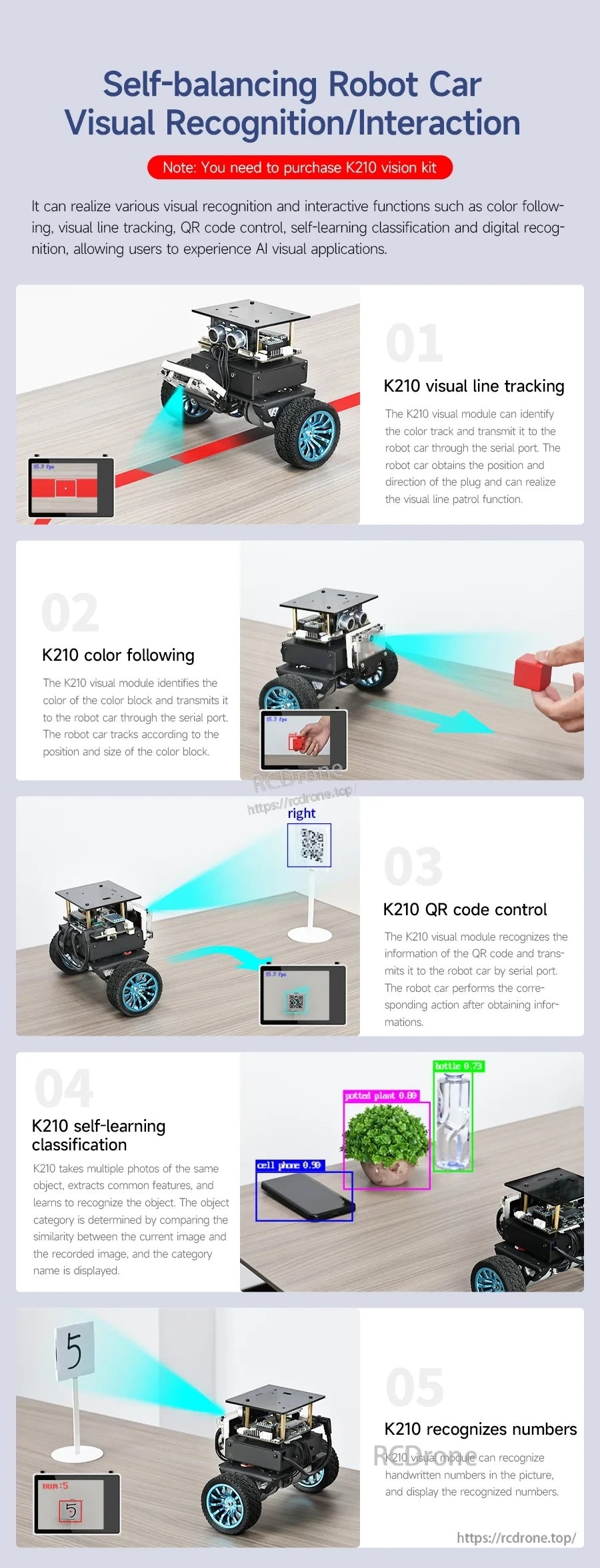
De Yahboom STM32 zelfbalancerende robotauto ondersteunt lijnvolging, kleurvolging, QR-codebesturing en visuele herkenningstaken voor interactieve projecten.
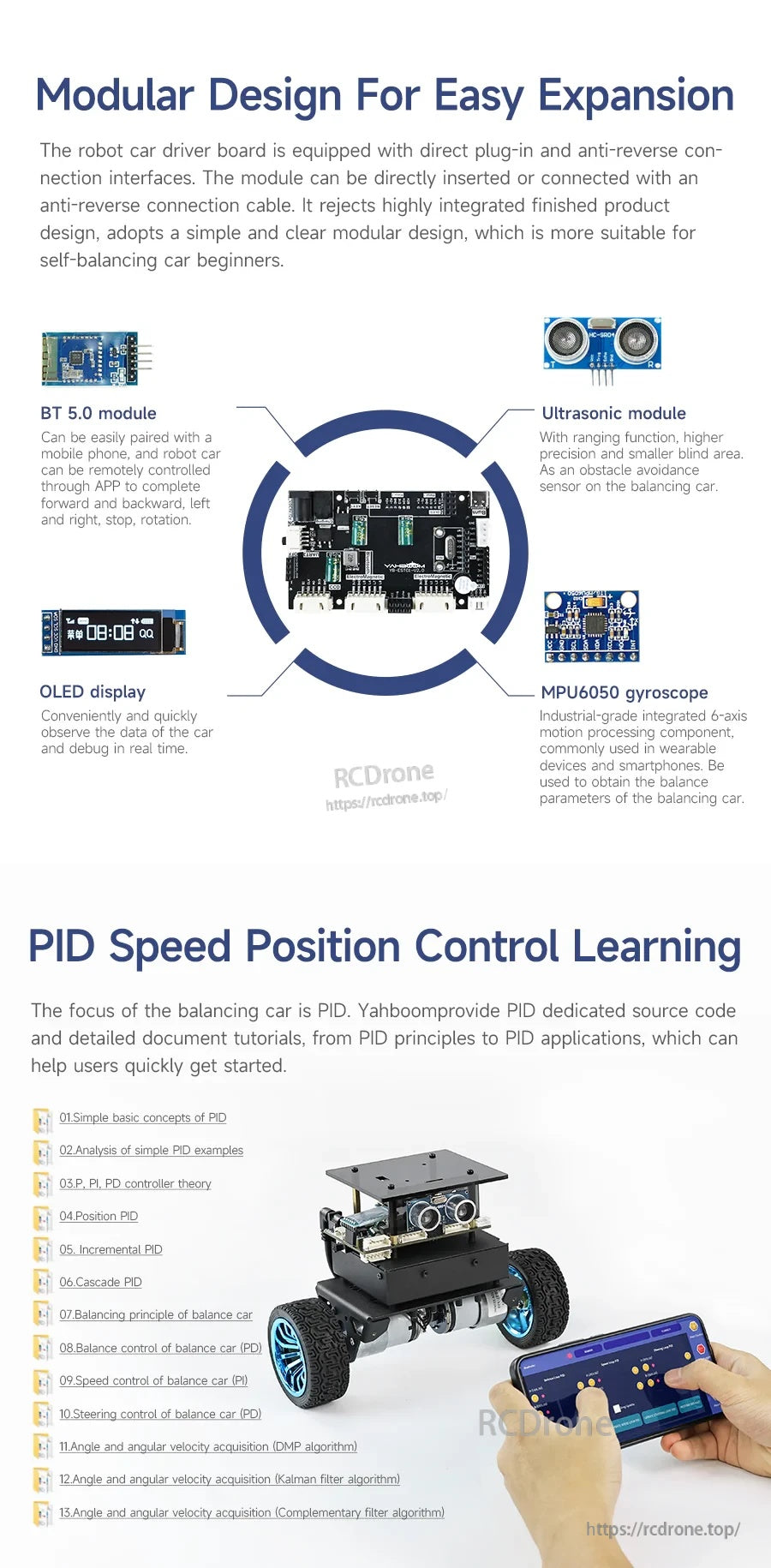
De Yahboom STM32 zelfbalancerende robot maakt gebruik van een modulaire controllerkaart met Bluetooth, ultrasone detectie, OLED-display en een MPU6050 gyromodule voor afstemming en PID-leren.
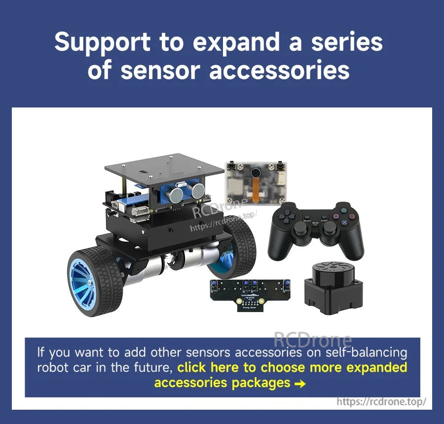
De Yahboom STM32 zelfbalancerende robotkit ondersteunt extra sensoraccessoires en bevat een chassis met twee wielen, cameramodule en gamepad-stijl controller.
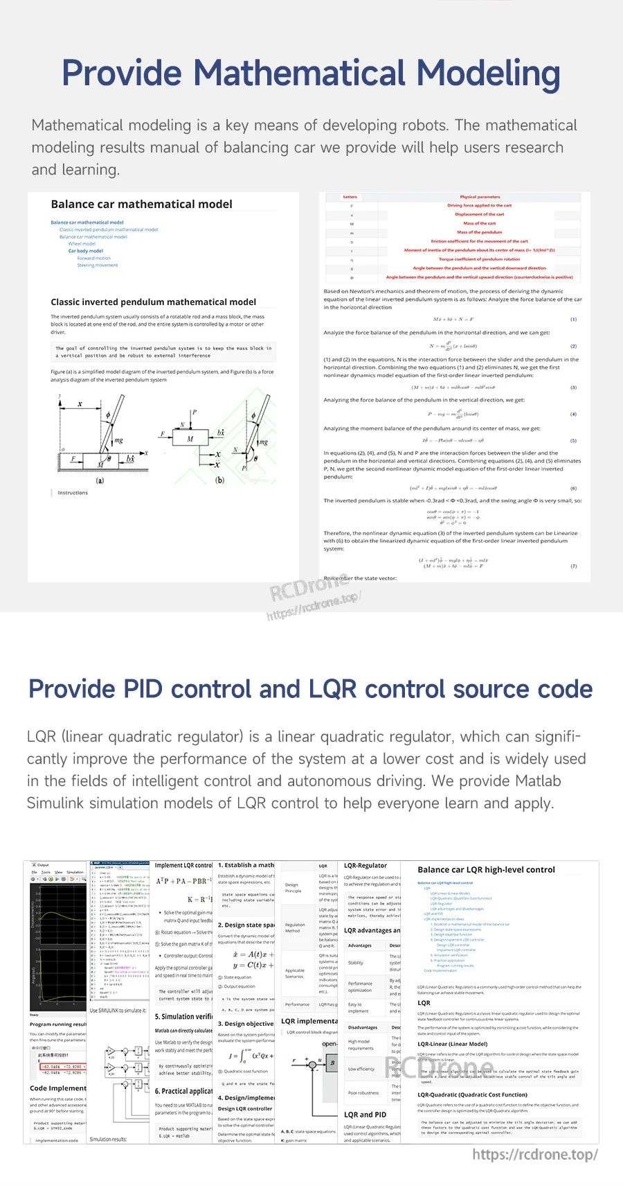
Wiskundige modelleringsnotities en PID/LQR-controle broncode ondersteunen afstemming en controleontwikkeling voor de STM32 zelfbalancerende robot.
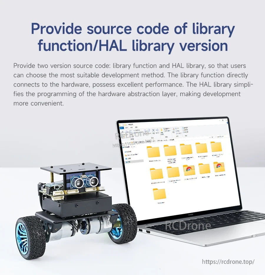
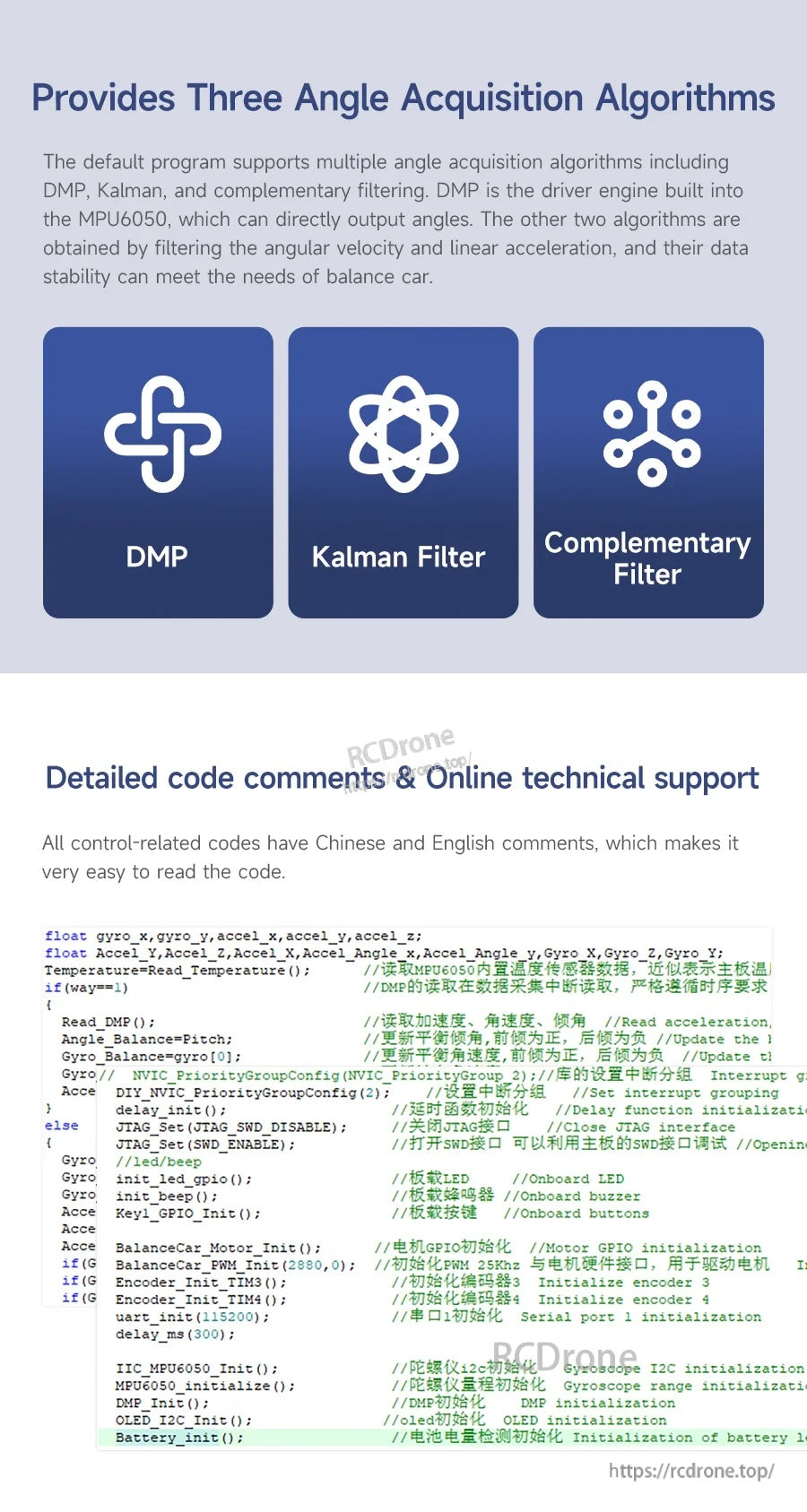
De Yahboom STM32 zelfbalancerende robot wordt geleverd met downloadbare broncode mappen, inclusief bibliotheekfunctie en HAL-versies voor ontwikkeling.

De Yahboom STM32 zelfbalancerende robot bevat een gedetailleerde functiedocumentatie voor ontwikkeling en een BSP-rijdatabase document ter ondersteuning van codering en installatie.
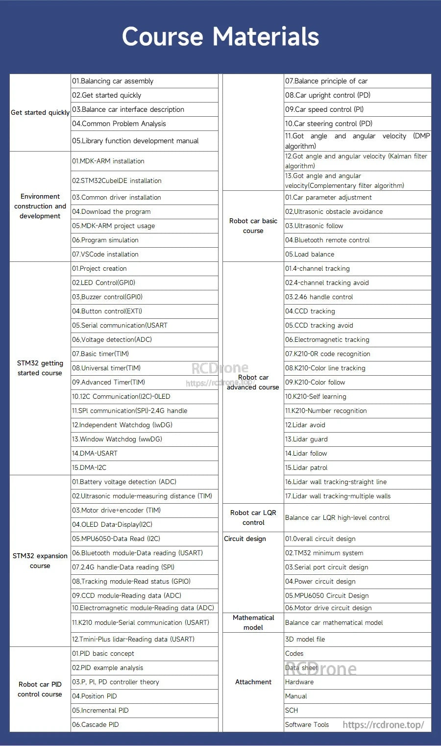
Yahboom STM32 zelfbalancerende robotcode ondersteunt DMP, Kalman-filter en complementaire filteropties voor hoekacquisitie en afstemming.
De Yahboom STM32 zelfbalancerende robotcursusmaterialen bevatten stapsgewijze lessen over montage, STM32CubeIDE-programmering en PID-afstemming.

De Yahboom STM32 zelfbalancerende robotdocumentatie bevat georganiseerde tutorialmappen en videolessen om de installatie en programmering te begeleiden.
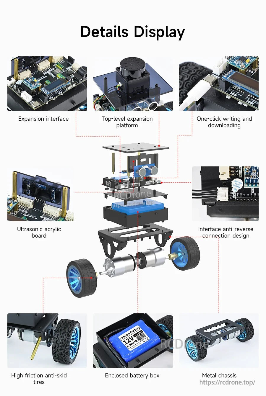
De STM32 zelfbalancerende robot maakt gebruik van een metalen chassis met een ingesloten batterijbox, antislipwielen en modulaire uitbreidings- en sensorborden voor eenvoudige montage.
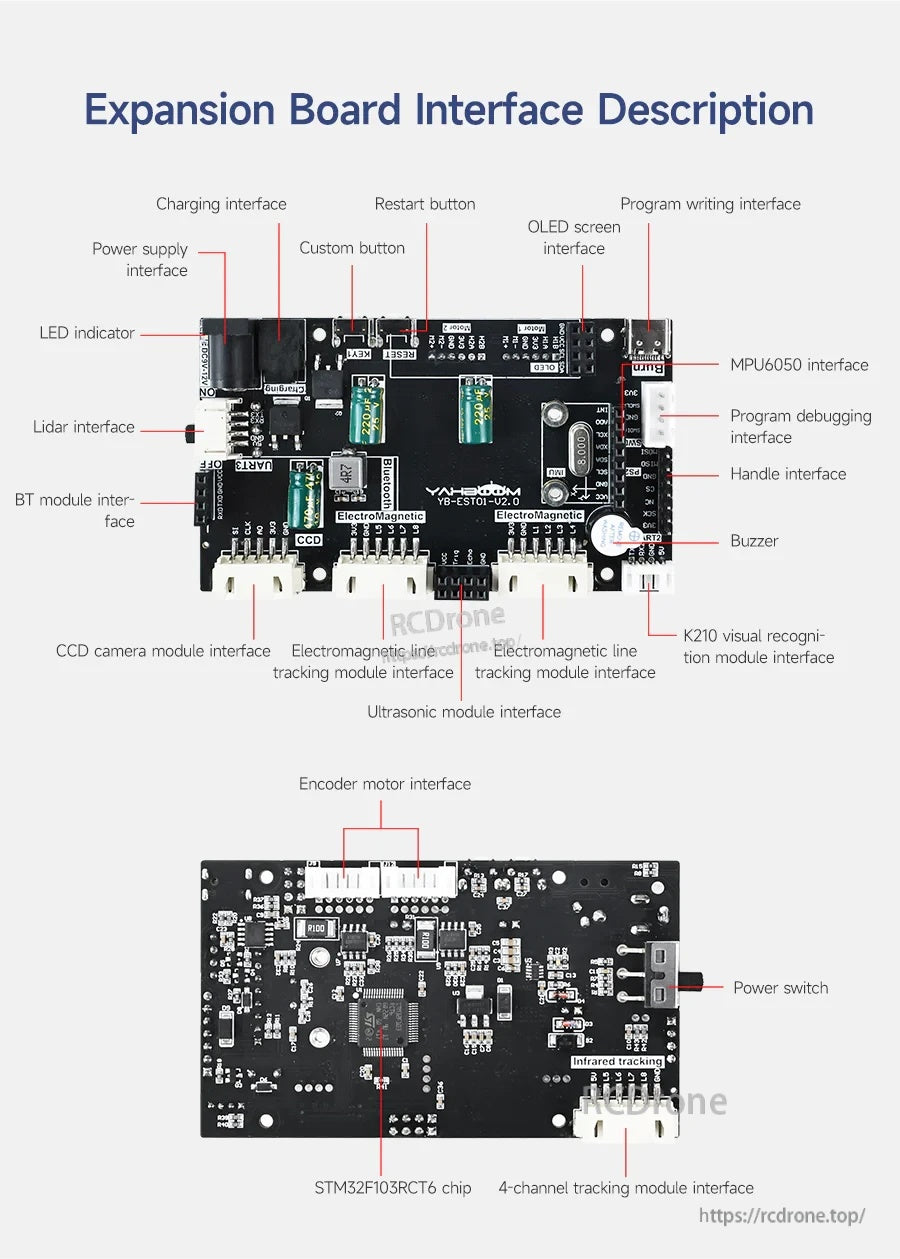
Het STM32-robotuitbreidingsbord maakt gebruik van duidelijk gelabelde connectors voor stroom, motoren, sensoren (MPU6050, ultrasoon, lidar) en programmering om bedrading en installatie te vereenvoudigen.
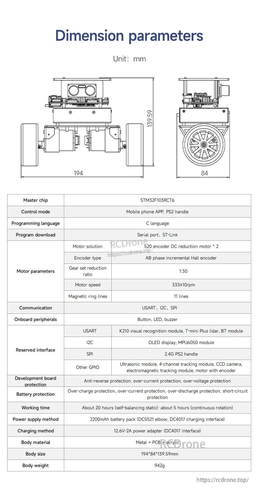
De Yahboom STM32 zelfbalancerende robot maakt gebruik van een STM32F103C8T6-controller en vermeldt een 7.
4V 2200mAh batterij samen met belangrijke afmetingen voor pasplanning.
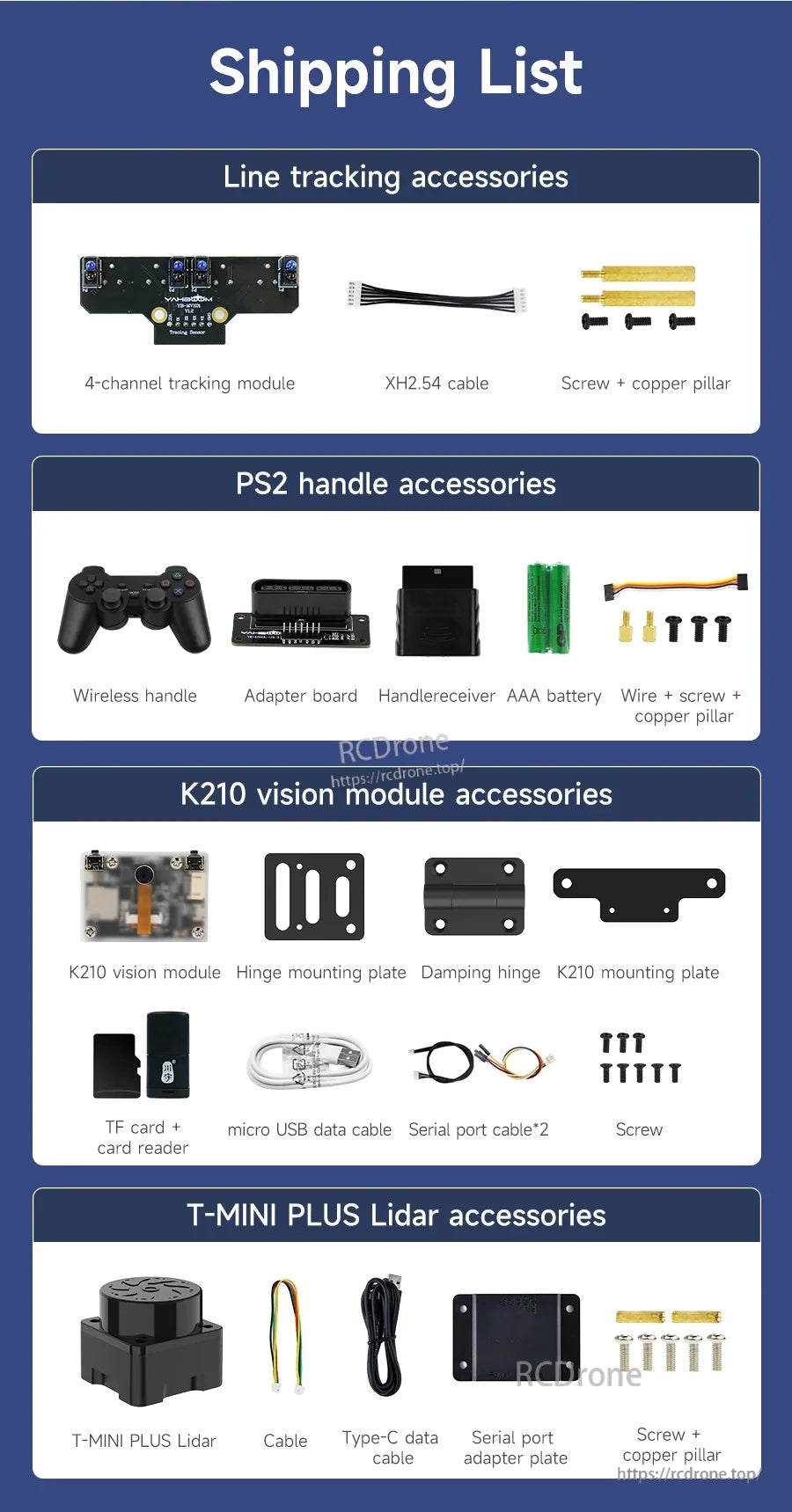
De Yahboom STM32 zelfbalancerende robotkit bevat lijnvolgaccessoires, een PS2 draadloze handgreepset, K210 vision module onderdelen, en T-MINI PLUS LiDAR accessoires voor uitbreiding.