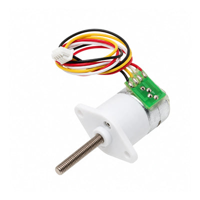
CHIHAI CHS-1528BY-ABHL Geared Stepper Motor with Hall Encoder, 100:1
CHIHAI CHS-1528BY-ABHL Geared Stepper Motor with Hall Encoder, 100:1
CHIHAI MOTOR
Nie udało się wczytać dostępności odbioru


Overview
The CHIHAI MOTOR CHS-1528BY-ABHL is a compact two-phase, four-wire geared stepper motor with an incremental Hall encoder. This listing supplies the housed steel-gear 100:1 configuration, a 3 mm D-shaped shaft and separate motor and encoder leads. Encoder feedback can be used by a compatible external controller for closed-loop motion; the motor assembly does not include a complete closed-loop driver.
Features
- Nominal 100:1 reduction; source actual ratio reference 99.3:1.
- Two-phase, four-wire stepper with 30 Ω windings and 5 V motor reference.
- AB-channel incremental magnetic Hall feedback with 7 PPR base output at the motor.
- Steel reduction gears and plate structure under a white outer housing.
- 3 mm D-shaft, 9 mm shaft projection and compact 15 mm diameter motor body.
Specifications
| Parameter | Value |
|---|---|
| Model | CHS-1528BY-ABHL |
| Supplied configuration | Motor with outer housing, steel plate gearbox, nominal 100:1 |
| Motor | Two phases, four wires, bipolar stepper |
| Motor voltage reference | 5 V DC; source performance table uses L6219 driver IC |
| Phase current | 150 mA per phase, source reference |
| Phase resistance | 30 Ω ±7% per phase |
| Phase inductance | 9.5 mH per phase |
| Actual gear ratio reference | 99.3:1 |
| Output full-step angle | 0.18° source nominal reference; not a positioning-accuracy specification |
| Output speed reference | 30 RPM in source 1000 PPS test; actual speed depends on pulse rate and load |
| Output holding / pull-out torque | 1.40 / 0.40 kgf·cm in source reference table |
| Maximum gearbox torque | 3.0 kgf·cm source permitted limit, not the continuous rating for this SKU |
| Shaft | 3 mm nominal D-shaft, 9 mm projection; see drawing for tolerances |
| Mechanical envelope | 15 mm body diameter; 28.0 mm drawing body-length reference; front flange 24.2 mm overall width |
| Mounting | Two 2.10 mm holes, 20.00 mm center spacing, see drawing |
| Leads / connectors | 150 ±5 mm drawing reference; two 1.25 mm-pitch 4-pin connectors |
| Motor mass | Approximately 18 g, source net-mass reference |
Hall Encoder
The AB-channel incremental encoder supplies feedback for speed and relative position measurement. Its 7 PPR base output is multiplied by the gear reduction when referenced to the output shaft, approximately 700 pulses per nominal output revolution at 100:1 before any quadrature decoding. The mechanical ratio and decoder mode determine the resulting count; this is not an absolute-angle or accuracy specification.
| Encoder parameter | Source specification |
|---|---|
| Type | AB two-channel incremental magnetic Hall encoder |
| Supply | 3.3 V DC or 5.0 V DC |
| Signal | AB square waves; onboard pull-up / signal conditioning |
| Interface | ZH 1.25 mm, 4-pin, supplied lead |
| Response frequency | 100 kHz source reference |
| Base pulses | 7 PPR at the motor |
| Magnetic ring | 14 poles / 7 pole pairs |
Motor and Encoder Wiring
| Circuit | Wire | Connection |
|---|---|---|
| Motor | Black | A+ |
| Motor | Blue | B+ |
| Motor | Red | A− |
| Motor | Yellow | B− |
| Encoder | Red | VCC Hall power input |
| Encoder | Black | GND |
| Encoder | Yellow | C2, encoder channel B |
| Encoder | Blue | C1, encoder channel A |
Black/red form motor phase A and blue/yellow form motor phase B. Use a suitable two-phase bipolar stepper driver with an appropriate phase-current setting. Keep the motor supply/phase circuit separate from the 3.3 V or 5 V encoder supply and logic signals. Verify connector orientation and controller input compatibility. Disconnect power before changing wiring. Do not power motor windings directly from a DC supply or apply higher motor-test voltages to the encoder.
Gearmotor Family Reference
The following source table was specified at 5.0 V DC with an L6219 driver. Only the housed nominal 100:1 version is sold in this listing; the other ratios are comparison references. Speed is shown for the source 1000 PPS condition, and holding torque is a stationary value distinct from running pull-out torque.
| Nominal ratio | Actual ratio | Output step (°) | 1000 PPS speed (RPM) | Holding (kgf·cm) | Pull-out (kgf·cm) |
|---|---|---|---|---|---|
| 10:1 | 9.68 | 1.86 | 300 | 0.14 | 0.04 |
| 20:1 | 19.36 | 0.93 | 200 | 0.28 | 0.08 |
| 30:1 | 29.47 | 0.61 | 100 | 0.42 | 0.12 |
| 50:1 | 51.1 | 0.35 | 60 | 0.7 | 0.2 |
| 100:1 — sold here | 99.3 | 0.18 | 30 | 1.4 | 0.4 |
| 150:1 | 150.96 | 0.12 | 20 | 2.1 | 0.6 |
| 210:1 | 209.76 | 0.086 | 14 | 2.9 | 0.84 |
| 298:1 | 297.9 | 0.06 | 10 | Max 3.0 | 1.2 |
| 380:1 | 379.16 | 0.047 | 8 | Max 3.0 | 1.5 |
The source also lists starting frequency greater than 1200 PPS and response frequency greater than 900 PPS without complete test conditions. These are source references, not guaranteed operating limits under an application load.
Drive Test Reference and Thermal Care
The source provides the following 15BY drive references for 30 Ω ±7% windings. These test-current values differ from the per-phase rating and are not a universal current setting. Motor reference voltage remains 5 V; higher test supply values require a compatible driver and current control. Encoder supply remains 3.3 V or 5 V.
| Source test supply | Recommended test pulse rate | Source test current |
|---|---|---|
| 12.0 V | 1000 PPS/Hz | ≤0.25 A |
| 7.40 V | 1000 PPS/Hz | ≤0.15 A |
| 6.00 V | 1000 PPS/Hz | ≤0.10 A |
| 5.00 V | 1000 PPS/Hz | ≤0.08 A |
| 3.70 V | 700 PPS/Hz | ≤0.07 A |
Monitor motor temperature during extended operation. Add a cooling pause or external cooling if temperature rises excessively. Avoid overloads, sustained stalls and repeated blocking. Size the mechanism using running torque with margin; encoder feedback does not remove mechanical load limits. Sound and vibration vary with pulse rate and load.
Applications
Suitable for small robotic mechanisms, smart-appliance motion, compact pan/tilt systems and focus mechanisms that need geared step motion and incremental position feedback. Confirm the driver, controller, shaft coupling, mounting clearances and operating torque for the mechanism.
What's Included
- 1 × CHS-1528BY-ABHL geared stepper motor with Hall encoder and outer housing, nominal 100:1.
- Motor and encoder wiring with 1.25 mm-pitch 4-pin connectors as shown.
External stepper driver, feedback controller, power supply, coupling and application mechanism are not included.
FAQ
Is this a complete closed-loop servo?
No. It is a geared stepper motor with encoder feedback. Closed-loop operation requires a compatible external driver and controller.
Does the encoder use the same voltage as the motor?
The motor reference is 5 V. The encoder accepts 3.3 V or 5 V and has separate power and signal connections. Higher motor drive-test supplies must not be connected to the encoder.
Can I select another gear ratio?
No. Only the housed steel-gear nominal 100:1 configuration is available here.
Visual Details