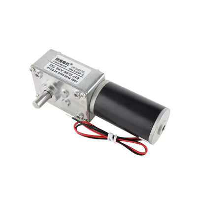
CHIHAI MOTOR CHS-GM12-10BY 2-Phase Geared Stepper Motor, 5V
CHIHAI MOTOR CHS-GM12-10BY 2-Phase Geared Stepper Motor, 5V
CHIHAI MOTOR
Nie udało się wczytać dostępności odbioru


Overview
The CHIHAI MOTOR CHS-GM12-10BY is a miniature two-phase, four-wire geared stepper motor for compact positioning mechanisms. Its metal gearbox reduces the motor's 18° input step angle to a smaller output increment. Choose the ratio, shaft projection and motor-only or reciprocating-driver package.
Features
- Compact metal gear train and a 3 mm D-shaped output shaft.
- Nine nominal ratios from 10:1 to 380:1, with actual ratios listed below.
- Pulse-controlled angular movement through a compatible stepper driver.
- 10 mm and 4.4 mm shaft-projection choices where available.
- Optional button-control reciprocating driver, with a bare-board or enclosed version.
Specifications
| Specification | Value |
|---|---|
| Brand / model | CHIHAI MOTOR / CHS-GM12-10BY |
| Motor configuration | Two-phase, four-wire geared stepper; metal reduction gears |
| Nominal motor voltage | 5V DC through a compatible stepper driver |
| Motor step angle before reduction | 18° |
| Phase resistance | 39 Ω ±7% |
| Phase inductance | 14.3 mH per phase |
| Phase current reference | 128 mA per phase at 5V, L6219 driver reference |
| Motor outline | Approximately 10 × 12 × 20 mm |
| Shaft projection choices | 10 mm or 4.4 mm, depending on available configuration |
| Shaft diameter / D-flat | 3 mm diameter / 2.5 mm across flat |
| Mounting references | 2 × M1.6; see dimension drawing for the selected shaft |
| Dimension drawing references | Motor length 10.5 ±0.2 mm; gearbox reference 9 mm; plate thickness 1.0 mm; register diameter 4 mm |
| Motor wire / connector | 75 ±10 mm illustrated lead length; 1.25 mm-pitch 4-pin connector, 51021-0400 drawing reference; AWG30 UL1571 wire marking |
| Motor weight | Approximately 11 g |
| Pulse-frequency references | Maximum self-start pulse frequency >1200 PPS; maximum response pulse frequency >900 PPS, under the stated 5V/L6219 reference conditions |
Reduction Ratio and Output Performance
The following values apply to a 5V motor with an L6219 driver reference. Nominal selector ratios are rounded; use the actual ratio when calculating output speed or step increments. Maximum allowable gearbox torque is distinct from holding torque and running output torque.
| Nominal ratio | 10:1 | 20:1 | 30:1 | 50:1 | 100:1 | 150:1 | 210:1 | 298:1 | 380:1 |
|---|---|---|---|---|---|---|---|---|---|
| Actual reduction ratio | 9.68 | 19.36 | 29.47 | 51.1 | 99.3 | 150.96 | 209.76 | 297.9 | 379.16 |
| Output step angle (°) | 1.86 | 0.93 | 0.61 | 0.35 | 0.18 | 0.12 | 0.086 | 0.06 | 0.047 |
| Holding torque (kgf·cm) | 0.12 | 0.24 | 0.36 | 0.6 | 1.2 | 1.8 | 2.5 | Not specified | Not specified |
| Maximum allowable torque (kgf·cm) | Not specified | Not specified | Not specified | Not specified | Not specified | Not specified | Not specified | 3.0 | 3.0 |
| Output torque (kgf·cm) | 0.03 | 0.06 | 0.09 | 0.15 | 0.3 | 0.45 | 0.63 | 0.9 | 1.1 |
Drive Frequency Reference
The following full-step drive test used a 39 Ω motor and a stepper-motor tester. Speeds are motor speeds before the gearbox; divide by the actual reduction ratio for the output speed. Choose a drive frequency without abnormal resonance. Higher pulse rates reduce the available torque. These test values do not establish a universal supply range for every driver; the nominal motor supply is 5V.
| Test parameter | 6.0V | 5.0V | 3.7V |
|---|---|---|---|
| Maximum drive frequency (Hz) | 1400 | 1300 | 800 |
| Motor speed at maximum frequency (rpm) | 4200 | 3900 | 2400 |
| Current at maximum frequency (A) | ≤0.12 | ≤0.085 | ≤0.085 |
| Minimum drive frequency (Hz) | 800 | 700 | 500 |
| Motor speed at minimum frequency (rpm) | 2400 | 2100 | 1500 |
| Current at minimum frequency (A) | ≤0.18 | ≤0.155 | ≤0.125 |
| Holding current at 0 Hz (A) | ≤0.30 | ≤0.25 | ≤0.19 |
Wiring and Installation
The phase pairs are white/red for phase A and brown/black for phase B. The connector pin numbering and the motor solder-pad order are different; use the corresponding diagram rather than assuming that the positions match.
| Connector pin | Wire color | Phase |
|---|---|---|
| 1 | Brown | B+ |
| 2 | Black | B− |
| 3 | White | A+ |
| 4 | Red | A− |
| Motor solder-pad order in the illustrated board | Wire color | Phase |
|---|---|---|
| 1 | White | A+ |
| 2 | Black | B− |
| 3 | Red | A− |
| 4 | Brown | B+ |
Use a suitable two-phase stepper driver; do not connect the motor phase wires directly to a DC supply. Verify phase order, driver voltage/current settings and mechanical clearances before operating. Do not overload or stall the gearbox.
Configuration Guide
Choose one available package, nominal ratio and shaft projection. Some ratio/shaft combinations are unavailable. The motor-only option includes its attached lead harness but no driver. The current driver packages show a display and buttons, with an enclosed version offered separately.
An earlier driver board is shown in the reference visual. Its inward jumper position uses 6–18V DC; the outward position uses 4–6V DC, with 6–12V recommended for that pictured version. These instructions apply only to that earlier board. Follow the actual selected driver's own markings and instructions; do not transfer the earlier board's jumper or voltage settings to another version.
Applications
For compact pan/tilt mechanisms, motorized selfie mechanisms, camera tracking, small robots, miniature manipulators and printing mechanisms when their load, motion range, drive and mounting requirements match the selected configuration. Application images are illustrative; the pictured equipment is not included.
What's Included
| Selected package | Contents |
|---|---|
| Motor Only | 1 × selected GM12-10BY motor with attached four-wire harness |
| Motor + Reciprocating Driver | 1 × selected motor with harness; 1 × button-control reciprocating driver board |
| Motor + Enclosed Reciprocating Driver | 1 × selected motor with harness; 1 × enclosed button-control reciprocating driver |
A power supply, external controller and application equipment are not included unless explicitly named in the selected package.
FAQ
Can I power the motor by connecting its wires directly to 5V?
No. It needs a compatible two-phase stepper driver that energizes the phase pairs in sequence.
Why do the exact ratios differ from the option labels?
The option labels use rounded nominal ratios. Use the exact-ratio table for output speed and step-angle calculations.
Is a driver included with Motor Only?
No. Choose a driver package for the bare-board or enclosed reciprocating driver.
Do the legacy jumper settings apply to the current driver packages?
No. The reference image shows an earlier board. Use the markings and instructions for the driver supplied with the selected package.
Visual Details