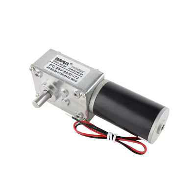
CHIHAI MOTOR CHS-GM12-15BY Geared Stepper Motor, 15mm
CHIHAI MOTOR CHS-GM12-15BY Geared Stepper Motor, 15mm
CHIHAI MOTOR
Nie udało się wczytać dostępności odbioru


Overview
The CHIHAI MOTOR CHS-GM12-15BY is a miniature geared stepper with a two-phase four-wire motor, metal reduction gears and a D-shaped shaft. Select the reduction ratio,4.4 mm or10 mm output-shaft projection and the required motor, driver or bracket package. This compact electric motor uses a sequenced pulse drive for positioning and speed adjustment.
Features
- 18° motor input step with ratio-dependent output increments.
- Nine nominal reduction ratios, with precise mechanical ratios listed below.
- 3 mm D-shaped shaft with a 2.5 mm flat reference.
- Four-wire lead assembly and a 1.25 mm four-position connector reference.
- Optional reciprocating drivers, enclosed drivers, PLC-control versions and side-mount bracket.
Specifications
| Specification | Value / scope |
|---|---|
| Brand / model | CHIHAI MOTOR / CHS-GM12-15BY miniature geared stepper |
| Motor construction | Two-phase four-wire stepper with metal reduction gears |
| Motor input step | 18° |
| Electrical specification reference | 5V DC with L6219 driver reference |
| Drive configuration references | 5–12V drive guide; a separate3.7V low-voltage test is listed below with its own pulse/current conditions |
| Phase current / resistance / inductance | 150 mA per phase /30 Ω ±7% /9.5 mH per phase |
| Main body dimensions | 15 mm motor diameter ×20 mm assembly-length reference, excluding output-shaft projection |
| Selectable shaft projection | 4.4 mm or10 mm; the standard drawing and shared package photos show the 10 mm reference |
| Output shaft | 3 mm D-shaft;2.5 mm D-flat reference |
| Other standard drawing dimensions | 9 mm gearbox section within the 20 mm assembly reference;0.7 mm front offset;1 mm rear offset;4 mm front register;6 mm rear shaft/bearing reference |
| Front hole-pattern drawing | 12 mm front-plate height;9 mm hole-pattern reference;two M1.4 andtwo M1.6 callouts |
| Connector | 1.25-4Y four-position connector /1.25 mm reference |
| Lead marking reference | GB1571 30 /UL AWM105° marking; this does not establish complete-motor operating temperature |
| Pin order | 1 white A+;2 black B−;3 red A−;4 yellow B+ |
| Motor weight | Approximately13 g reference |
| Working pulse-rate guide | 800–1200 pulses/s in the 5–12V feature reference |
| Starting / response pulse references | Starting >1200 pulses/s; response >900 pulses/s as separately listed motor references |
Ratio Selection and Performance
The following motor reference table uses 5V DC and an L6219 driver. Output step and speed vary with the actual mechanical ratio and drive conditions. The speed row is referenced to 1000 input pulses/s. Holding and pull-out torque are different operating conditions.
| Nominal ratio | Precise ratio | Output step (°) | Speed at 1000 pulses/s (rpm) | Holding torque (kgf·cm) | Pull-out torque (kgf·cm) |
|---|---|---|---|---|---|
| 10:1 | 9.68:1 | 1.86 | 300 | 0.14 | 0.04 |
| 20:1 | 19.36:1 | 0.93 | — | 0.28 | 0.08 |
| 30:1 | 29.47:1 | 0.61 | 100 | 0.42 | 0.12 |
| 50:1 | 51.1:1 | 0.35 | 60 | 0.70 | 0.20 |
| 100:1 | 99.3:1 | 0.18 | 30 | 1.40 | 0.40 |
| 150:1 | 150.96:1 | 0.12 | 20 | 2.10 | 0.60 |
| 210:1 | 209.76:1 | 0.086 | 14 | 2.90 | 0.84 |
| 298:1 | 297.9:1 | 0.06 | 10 | Maximum 3.0 | 1.20 |
| 380:1 | 379.16:1 | 0.047 | 8 | Maximum 3.0 | 1.50 |
For the 298:1 and 380:1 nominal versions,3.0 kgf·cm is a maximum permissible holding-torque limit, not a minimum torque guarantee. Avoid stalled or overloaded operation.
Wiring and Driver Selection
Connector pin order is 1 white A+,2 black B−,3 red A− and 4 yellow B+. White/red form phase A; black/yellow form phase B. Use a compatible two-phase bipolar stepper driver and orient the connector against the wiring drawing. The illustrated excitation sequence and CW/CCW arrows are referenced to the mounting/output-shaft viewing side.
The motor requires sequenced coil excitation. A5V electrical reference and a 5–12V drive guide do not make every driver/current setting interchangeable. The voltage/current guide below is a separate set of operating references for a 30 Ω ±7% winding. Follow the actual driver's ratings and set the phase current appropriately.
| Test supply | Recommended drive rate (pulses/s) | Suggested drive current (A) |
|---|---|---|
| 12.0V | 1000 | ≤0.25 |
| 7.40V | 1000 | ≤0.15 |
| 6.00V | 1000 | ≤0.10 |
| 5.00V | 1000 | ≤0.08 |
| 3.70V | 700 | ≤0.07 |
The electrical relationship is applied voltage = back EMF + phase current ×coil resistance. For extended operation, monitor motor temperature; add cooling pauses or external cooling when required. The105° lead-marking reference does not establish a complete-motor temperature rating.
The button-operated driver package provides reciprocating control. The PLC-control package provides a driver with external control terminals; the enclosed options include the corresponding housing. Check the actual connector functions and signal levels before connecting an external controller.
Mechanical Installation
Choose the output-shaft projection before fitting. The standard drawing and shared package photographs show the 10 mm shaft reference; the 4.4 mm option has its own selected projection. Do not infer that both shaft options share every dimension shown for the 10 mm reference.
Check the 3 mm shaft,2.5 mm flat, front hole pattern, connector clearance and bracket dimensions against the mechanism. The9 mm gearbox reference is part of the 20 mm assembly-length reference, rather than an extra section to add again.
| Optional side-mount bracket | Dimensions / contents |
|---|---|
| Bracket package | White side-mount bracket with the shown installation hardware |
| Base reference | 25 ×22 mm;3 mm thickness |
| Base mounting holes | Four2.0 mm holes;19 ×13 mm center-pattern references |
| Height / face references | 17.70 mm overall height;14.70 mm drawing reference;15 mm face width |
| Front interfaces | 4.0 mm central aperture;two 1.6 mm hole references;9 mm drawing reference |
Applications
For compatible miniature robots, robotic grippers, adjustable furniture mechanisms, automatic adjustment assemblies and small pan-tilt mechanisms where the step resolution, driver, load and mounting dimensions fit the selected configuration.
What's Included
| Selected package | Contents |
|---|---|
| Motor with Leads | 1 motor with attached lead/connector assembly |
| Motor with Leads + Reciprocating Driver | 1 motor and 1 button-operated reciprocating driver |
| Motor with Leads + Enclosed Reciprocating Driver | 1 motor and 1 enclosed button-operated reciprocating driver |
| Motor with Leads + PLC-Control Driver | 1 motor and 1 PLC-control driver with external control terminals |
| Motor with Leads + Enclosed PLC-Control Driver | 1 motor and 1 enclosed PLC-control driver |
| Motor with Leads + Side-Mount Bracket | 1 motor,1 white side-mount bracket and the shown installation hardware |
Each selection includes one motor at the selected ratio and shaft projection. A driver, enclosure or bracket is included only when named in the package. A power supply, PLC, host controller and application equipment are not included.
FAQ
Why do the photos show a longer shaft than the 4.4 mm option?
The package photos are shared references and show the 10 mm shaft. Select the required 4.4 mm or10 mm projection and check the corresponding fit.
Does the 3.0 kgf·cm value guarantee holding torque at high ratios?
No. For the 298:1 and 380:1 nominal versions, it is a maximum permissible limit rather than a minimum guarantee.
Can every supply voltage use the same current setting?
No. The guide lists different current and pulse-rate references by voltage. Match the actual driver and monitor heat during extended operation.
What is different about the PLC-control package?
It includes the version with external control terminals. Check its terminal functions and signal levels against the intended controller.
Does the motor-only package include the white bracket?
No. Select the side-mount bracket package for the bracket and shown installation hardware.
Visual Details