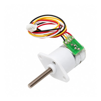
CHIHAI CHS-GM12-15BY M3 Screw Shaft Stepper Motor, 298:1
CHIHAI CHS-GM12-15BY M3 Screw Shaft Stepper Motor, 298:1
CHIHAI MOTOR
Nie udało się wczytać dostępności odbioru


Overview
The CHIHAI MOTOR CHS-GM12-15BY M3 is a miniature two-phase, four-wire geared stepper motor with a threaded M3 output shaft and a fixed 298:1 reduction. Choose an exposed gearbox or a version with a protective cover, then select the motor alone or a package with a simple test driver, an M3 flange attachment, or both.
Features
- Metal reduction gears with a fixed 298:1 gearbox.
- M3 screw shaft for compact positioning mechanisms; shaft dimensions differ between cover versions.
- 18° input step divided by 298 gives approximately 0.06° per output full step.
- Four-wire lead and compact green terminal PCB; external bipolar stepper drive required.
- Two housing versions and four actual accessory packages, with no invented ratio choices.
Specifications
| Parameter | Source specification / scope |
|---|---|
| Brand / model | CHIHAI MOTOR / CHS-GM12-15BY M3 |
| Motor | Two-phase, four-wire geared stepper |
| Gear reduction | 298:1, fixed in every package sold here |
| Shaft | M3 standard threaded shaft; not the M4 ×55 mm model |
| Without protective cover (Version A) | 20.0 ±0.2 mm shaft projection; 19.50 mm body drawing reference |
| With protective cover (Version B) | 16.8 mm threaded portion; 18.8 mm total shaft projection; 22.5 mm maximum body reference |
| Motor body diameter | 15 mm drawing reference |
| Covered mounting flange | 24.2 mm overall width; 20.00 mm hole centers; two 2.10 mm holes; see drawing |
| Open gearbox mounting | Two M1.6 callouts in source front view; use the version-specific drawing |
| Motor voltage reference | 5 V DC; source maximum drive reference 12 V with a suitable driver |
| Output step | 0.06° ±7% source reference at 298:1; not a positioning-accuracy guarantee |
| Phase resistance | 30 Ω ±7% |
| Phase inductance | 9.5 mH ±20% |
| Detent / holding torque references | 1300 gf·cm REF detent; 1300 gf·cm minimum holding, source table without complete conditions |
| Pull-out torque reference | 1000 gf·cm minimum in source table; not a guaranteed continuous application rating |
| Starting / response frequency references | 1000 Hz minimum / 800 Hz minimum as separately listed by source; test conditions incomplete |
| Cable / connector | 150 ±5 mm drawing lead reference; 1.25 mm four-position connector |
| Motor mass | Approximately 15 g net-mass source reference |
Housing and Package Selection
The source names the shaft family “20M3”, but the covered version drawing distinguishes a 16.8 mm threaded portion from an 18.8 mm total projection. Use the drawing for the housing version selected. The protective cover changes the mechanical envelope; it does not establish a dustproof or waterproof rating. Shaft length is not a guaranteed usable linear stroke.
| Package | Contents |
|---|---|
| Motor Only | 1 × motor in selected housing version |
| Motor + Test Driver | 1 × motor; 1 × simple stepper test driver board |
| Motor + Flange Nut | 1 × motor; 1 × M3 flange attachment listed as a flange nut |
| Motor + Flange Nut + Test Driver | 1 × motor; 1 × M3 flange attachment; 1 × simple stepper test driver board |
The flange accessory is shown by the source as a flange nut/coupler with an M3 thread reference. Check its geometry and attachment method for the mechanism. Motor-only packages do not include the driver or flange accessory. A power supply, linear guide, end stops, mounting mechanism and application controller are not included.
Wiring and Operation
| Connector pin | Wire | Motor phase |
|---|---|---|
| 1 | White | A+ |
| 2 | Black | B− |
| 3 | Red | A− |
| 4 | Yellow | B+ |
White and red form phase A; yellow and black form phase B. Use a compatible two-phase bipolar stepper driver, set the appropriate winding current and check temperature under load. Do not connect the motor windings directly to a DC supply. Disconnect power before changing connections. Rotation direction follows the drive sequence and phase order.
Optional Test Driver
The source describes the small board as a simple test driver. With the yellow jumper in the inner/default position, the board supply reference is 6–18 V DC; the outer position is specified for 4–6 V DC. The source recommends 6–12 V DC. Power down before moving the jumper and check its position before applying power. The board supply range does not override the motor's voltage/current and thermal limits. Use the source-recommended range with suitable current control; do not assume that an 18 V board input is appropriate for this motor.
Drive Reference and Thermal Care
The following source 15BY drive table is for 30 Ω ±7% windings. Current figures are source test references, not a universal continuous phase-current setting. The general source text mentions 800–1200 PPS, while the table provides the specific conditions below. Operation depends on driver, pulse rate, load and temperature.
| Test supply | Source pulse rate | Source test current |
|---|---|---|
| 12.0 V DC | 1000 PPS/Hz | ≤0.25 A |
| 7.40 V DC | 1000 PPS/Hz | ≤0.15 A |
| 6.00 V DC | 1000 PPS/Hz | ≤0.10 A |
| 5.00 V DC | 1000 PPS/Hz | ≤0.08 A |
| 3.70 V DC | 700 PPS/Hz | ≤0.07 A |
Monitor temperature during long runs; allow cooling pauses or add external cooling if temperature rise becomes excessive. Avoid overloads, sustained stalls and repeated blocking. Holding torque is a stationary value and differs from torque while stepping. Size the mechanism with margin for running torque, friction and alignment. Sound and vibration vary with pulse rate and load.
Applications
Use this small screw-shaft motor for compact focusing, camera pan/tilt adjustment and miniature robotic positioning mechanisms. Design the guide and nut support for the actual mechanism; allowable axial load, linear positioning accuracy and usable stroke are not specified by the source.
FAQ
Can I select another reduction ratio?
No. All eight sales configurations use the fixed 298:1 gearbox.
Are both housing versions exactly the same shaft length?
No. Version A shows 20.0 ±0.2 mm projection. Version B shows a 16.8 mm threaded segment and 18.8 mm total projection. Check the corresponding drawing before installation.
Does every package include the driver and flange nut?
No. Choose the package that explicitly includes the required accessories. The source variant photo is shared by housing version and does not show every included accessory.
Visual Details