


Silnik przekładniowy JGB37-520 DC z enkoderem Halla, 12V/24V, 7–960 obr./min, metalowa przekładnia 37mm i wał D 6mm
Silnik przekładniowy JGB37-520 DC z enkoderem Halla, 12V/24V, 7–960 obr./min, metalowa przekładnia 37mm i wał D 6mm
Jiali Motor
Nie udało się wczytać dostępności odbioru


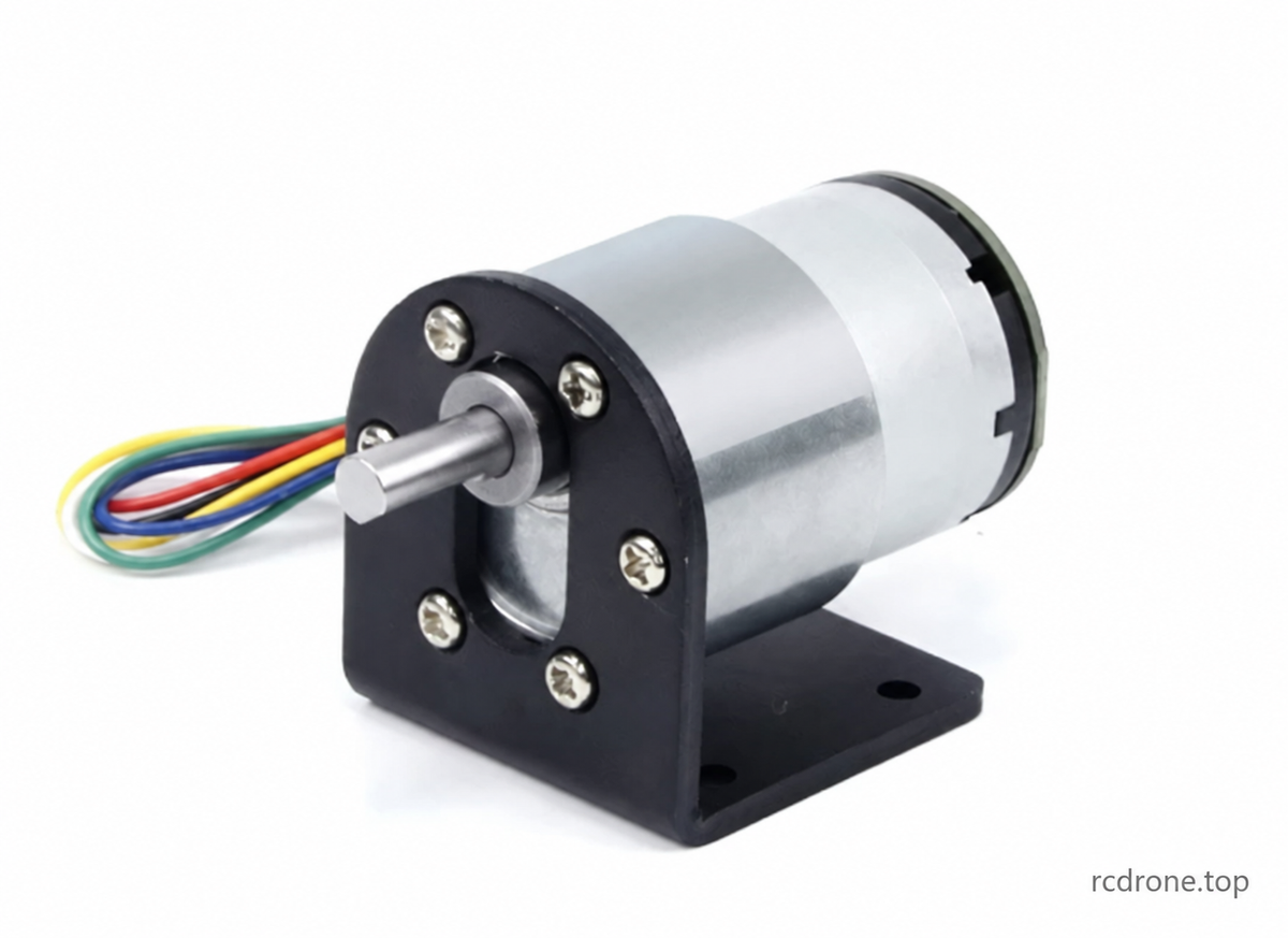
JGB37-520 Silnik z przekładnią DC z enkoderem Hall
JGB37-520 to kompaktowy silnik DC z przekładnią z enkoderem Hall A/B, metalową przekładnią redukcyjną, wałem wyjściowym w kształcie litery D o średnicy 6 mm oraz możliwością obrotu w obu kierunkach. Wybierz silnik 12V lub 24V, wymaganą prędkość wyjściową bez obciążenia oraz pakiet tylko z silnikiem lub akcesoriami do robotyki, małych mechanizmów i projektów elektronicznych.
Wybieralne prędkości to 7, 12, 22, 35, 45, 66, 107, 200, 319, 600 i 960 RPM. Opcje te odpowiadają serii silników dostawcy 6000RPM przed redukcją. Prędkość wyjściowa RPM mierzona jest bez obciążenia; prędkość maleje pod obciążeniem. Uchwyt pokazany na zdjęciu jest dołączony tylko wtedy, gdy wybrany pakiet wymienia uchwyt.
Budowa i kontrola prędkości
- Metalowe przekładnie redukcyjne w układzie wielostopniowym, miedziowe uzwojenie, silnik z magnesem trwałym i szczotki węglowe.
- Kontrola prędkości PWM jest możliwa z kompatybilnym zewnętrznym kontrolerem DC z szczotkami. Kontroler jest dołączony tylko w określonych pakietach.
- Odwróć tylko czerwone i białe przewody zasilające silnik, aby zmienić kierunek obrotów. Utrzymuj poprawną polaryzację zasilania enkodera i kontrolera; zatrzymaj silnik przed zmianą kierunku.
- Przełożenie przekładni określa kompromis między prędkością a momentem obrotowym. Zmniejszenie prędkości elektrycznie nie zapewnia takiego samego wzrostu momentu obrotowego jak wybór wyższego przełożenia.
Specyfikacje mechaniczne
| Parametr | Specyfikacja |
|---|---|
| Marka / model | Jiali Motor / JGB37-520 |
| Typ silnika | Silnik prądu stałego z przekładnią z enkoderem Hall A/B |
| Napięcie znamionowe | 12V DC lub 24V DC, w zależności od wybranej wersji |
| Średnica przekładni | 37mm |
| Średnica korpusu silnika / długość sekcji | 32mm / 22mm |
| Długość przekładni L | 19–29mm, w zależności od przełożenia |
| Wał wyjściowy | Średnica 6mm, wysunięcie 15.5mm; długość płaskiej części 12mm; 5.5mm na płasko |
| tolerancja średnicy wału | −0.03 / −0.05mm, jak zaznaczone na rysunku |
| gniazdo lokalizacyjne | średnica 12mm × wysokość 6mm |
| Montaż | Sześć otworów gwintowanych M3 na okręgu o średnicy 31mm; rysunek określa głębokość 3.5mm, zdjęcie określa 4mm. Zweryfikuj zaangażowanie śruby na rzeczywistym silniku. |
| Enkoder i kabel | średnica enkodera 32mm; projekcja tylnej zespołu 11.75mm; kabel PH2.0 sześciopinowy o długości około 144mm |
| przesunięcie wału | 7mm od linii środkowej silnika |
| współczynniki redukcji w odniesieniu dostawcy | 6.25:1–810:1; nie każdy stosunek odniesienia jest wybieralny |
| Waga tylko silnika | Około 144–170g w zależności od stosunku; przegląd podaje około 170g |
| Oceny przeglądu dostawcy | 2.4–10.8W i 0.15–0.65A w całej ilustrowanej serii; użyj poniższych tabel specyficznych dla serii |
| Twierdzenia operacyjne dostawcy | −10°C do 70°C; przegląd podaje 24-godzinne użytkowanie. Rzeczywista przydatność do pracy zależy od obciążenia i chłodzenia. |
| Hałas | Dostawca podaje około 55dB, zmieniający się w zależności od prędkości i obciążenia; warunki pomiaru nie są określone |
Wymiary są pomiarami referencyjnymi dostawcy i mogą się różnić. Wygląd silnika i komponenty mogą różnić się między wersjami.Enkoder dostarcza sygnały zwrotne; kontrola w pętli zamkniętej wymaga odpowiedniego zewnętrznego kontrolera. Twierdzenia dotyczące temperatury enkodera nie obejmują pełnego zakresu pracy silnika.
Seria silników 6000RPM — Odniesienie wydajności
Ta seria odpowiada wybieralnej rodzinie prędkości. Tabele zawierają również nienadające się do wyboru prędkości referencyjne dostawcy (85, 28, 15 i 9,5 RPM) dla pełności; nie tworzą dodatkowych opcji zakupu. Wartości są danymi dostawcy, a nie niezależnymi wynikami testów. Moment obrotowy podawany jest w kgf·cm, a nie w kilogramach nośności.
12V — 6000RPM przed redukcją
| Stosunek | Przekładnia L (mm) | RPM bez obciążenia | Prąd bez obciążenia (A) | RPM pod obciążeniem | Moment obrotowy przy max.efektywność (kgf·cm) | Obciążony prąd (A) | Moc (W) | Moment zastoju (kgf·cm) | Prąd zastoju (A) | Napięcie startowe (V) | Waga silnika (g) |
|---|---|---|---|---|---|---|---|---|---|---|---|
| 6.25 | 19 | 960 | 0.1 | 672 | 0.17 | 0.2 | 2.4 | 0.6 | 1.2 | 1.5 | 144 |
| 10 | 19 | 600 | 0.1 | 480 | 0.28 | 0.2 | 2.4 | 1.1 | 1.2 | 1.5 | 144 |
| 18.8 | 22 | 319 | 0.1 | 255 | 0.48 | 0.2 | 2.4 | 1.9 | 1.2 | 1.5 | 150 |
| 30 | 22 | 200 | 0.1 | 160 | 0.75 | 0.2 | 2.4 | 3 | 1.2 | 1.5 | 150 |
| 56 | 24 | 107 | 0.1 | 85 | 1.2 | 0.2 | 2.4 | 4.8 | 1.2 | 1.5 | 158 |
| 70 | 24 | 85 | 0.1 | 68 | 1.5 | 0.2 | 2.4 | 6 | 1.2 | 1.5 | 158 |
| 90 | 24 | 66 | 0.1 | 52 | 2 | 0.2 | 2.4 | 8 | 1.2 | 1.5 | 158 |
| 131 | 26.5 | 45 | 0.1 | 36 | 2.7 | 0.2 | 2.4 | 10.8 | 1.2 | 1.5 | 164 |
| 169 | 26.5 | 35 | 0.1 | 28 | 3.4 | 0.3 | 3.6 | 13.6 | 1.2 | 1.5 | 164 |
| 210 | 26.5 | 28 | 0.1 | 22 | 4.3 | 0.3 | 3.6 | 17.2 | 1.2 | 1.5 | 164 |
| 270 | 26.5 | 22 | 0.1 | 18 | 5.5 | 0.3 | 3.6 | 22 | 1.2 | 1.5 | 164 |
| 394 | 29 | 15 | 0.1 | 12 | 7.3 | 0.3 | 3.6 | 29.2 | 1.2 | 1.5 | 170 |
| 506 | 29 | 12 | 0.1 | 9.4 | 9.1 | 0.3 | 3.6 | 36.4 | 1.2 | 1.5 | 170 |
| 630 | 29 | 9.5 | 0.1 | 7.6 | 11.6 | 0.3 | 3.6 | 46.4 | 1.2 | 1.5 | 170 |
| 810 | 29 | 7 | 0.1 | 5.6 | 15 | 0.3 | 3.6 | 80 | 1.2 | 1.5 | 170 |
24V — 6000RPM przed redukcją
| Stosunek | Przekładnia L (mm) | RPM bez obciążenia | Prąd bez obciążenia (A) | RPM pod obciążeniem | Moment przy max.efektywność (kgf·cm) | Obciążony prąd (A) | Moc (W) | Moment zastoju (kgf·cm) | Prąd zastoju (A) | Napięcie startowe (V) | Waga silnika (g) |
|---|---|---|---|---|---|---|---|---|---|---|---|
| 6.25 | 19 | 960 | 0.05 | 672 | 0.17 | 0.15 | 3.6 | 0.6 | 0.6 | 2 | 144 |
| 10 | 19 | 600 | 0.05 | 480 | 0.28 | 0.15 | 3.6 | 1.1 | 0.6 | 2 | 144 |
| 18.8 | 22 | 319 | 0.05 | 255 | 0.48 | 0.15 | 3.6 | 1.9 | 0.6 | 2 | 150 |
| 30 | 22 | 200 | 0.05 | 160 | 0.75 | 0.15 | 3.6 | 3 | 0.6 | 2 | 150 |
| 56 | 24 | 107 | 0.05 | 85 | 1.2 | 0.15 | 3.6 | 4.8 | 0.6 | 2 | 158 |
| 70 | 24 | 85 | 0.05 | 68 | 1.5 | 0.15 | 3.6 | 6 | 0.6 | 2 | 158 |
| 90 | 24 | 66 | 0.05 | 52 | 2 | 0.15 | 3.6 | 8 | 0.6 | 2 | 158 |
| 131 | 26.5 | 45 | 0.05 | 36 | 2.7 | 0.15 | 3.6 | 10.8 | 0.6 | 2 | 164 |
| 169 | 26.5 | 35 | 0.05 | 28 | 3.4 | 0.15 | 3.6 | 13.6 | 0.6 | 2 | 164 |
| 210 | 26.5 | 28 | 0.05 | 22 | 4.3 | 0.15 | 3.6 | 17.2 | 0.6 | 2 | 164 |
| 270 | 26.5 | 22 | 0.05 | 18 | 5.5 | 0.15 | 3.6 | 22 | 0.6 | 2 | 164 |
| 394 | 29 | 15 | 0.05 | 12 | 7.3 | 0.15 | 3.6 | 29.2 | 0.6 | 2 | 170 |
| 506 | 29 | 12 | 0.05 | 9.4 | 9.1 | 0.15 | 3.6 | 36.4 | 0.6 | 2 | 170 |
| 630 | 29 | 9.5 | 0.05 | 7.6 | 11.6 | 0.15 | 3.6 | 46.4 | 0.6 | 2 | 170 |
| 810 | 29 | 7 | 0.05 | 5.6 | 15 | 0.15 | 3.6 | 80 | 0.6 | 2 | 170 |
Seria silników 10000RPM — Dodatkowe odniesienie dostawcy tylko
Dostarczony obraz zawiera również następujące serie silników o wyższej prędkości. To jest tylko informacja referencyjna: nie jest to osobno wybierana seria w tej ofercie.Nie stosuj tych wartości do zakupionej wersji 6000RPM, nawet jeśli prędkość obrotowa pokrywa się.
12V — 10000RPM przed redukcją (tylko do celów informacyjnych)
| Stosunek | Przekładnia L (mm) | RPM bez obciążenia | Prąd bez obciążenia (A) | RPM pod obciążeniem | Moment obrotowy przy maks. wydajności (kgf·cm) | Prąd pod obciążeniem (A) | Moc (W) | Moment obrotowy zablokowany (kgf·cm) | Prąd zablokowany (A) | Napięcie startowe (V) | Waga silnika (g) |
|---|---|---|---|---|---|---|---|---|---|---|---|
| 6.25 | 19 | 1600 | 0.15 | 1200 | 0.23 | 0.65 | 7.8 | 0.9 | 2.4 | 1.5 | 144 |
| 10 | 19 | 1000 | 0.15 | 770 | 0.4 | 0.65 | 7.8 | 1.6 | 2.4 | 1.5 | 144 |
| 18.8 | 22 | 530 | 0.15 | 407 | 0.67 | 0.65 | 7.8 | 2.6 | 2.4 | 1.5 | 150 |
| 30 | 22 | 333 | 0.15 | 250 | 1 | 0.65 | 7.8 | 4 | 2.4 | 1.5 | 150 |
| 56 | 24 | 178 | 0.15 | 140 | 1.8 | 0.65 | 7.8 | 7.2 | 2.4 | 1.5 | 158 |
| 70 | 24 | 142 | 0.15 | 110 | 2.2 | 0.65 | 7.8 | 8.8 | 2.4 | 1.5 | 158 |
| 90 | 24 | 110 | 0.15 | 85 | 3 | 0.65 | 7.8 | 12 | 2.4 | 1.5 | 158 |
| 131 | 26.5 | 76 | 0.15 | 58 | 3.9 | 0.65 | 7.8 | 15.6 | 2.4 | 1.5 | 164 |
| 169 | 26.5 | 60 | 0.15 | 46 | 5 | 0.65 | 7.8 | 20 | 2.4 | 1.5 | 164 |
| 210 | 26.5 | 47 | 0.15 | 36 | 6 | 0.65 | 7.8 | 24 | 2.4 | 1.5 | 164 |
| 270 | 26.5 | 37 | 0.15 | 28 | 8 | 0.65 | 7.8 | 32 | 2.4 | 1.5 | 164 |
| 394 | 29 | 25 | 0.15 | 19.5 | 10.4 | 0.65 | 7.8 | 41.6 | 2.4 | 1.5 | 170 |
| 506 | 29 | 20 | 0.15 | 15 | 13.6 | 0.65 | 7.8 | 54.4 | 2.4 | 1.5 | 170 |
| 630 | 29 | 15.8 | 0.15 | 12 | 16.6 | 0.65 | 7.8 | 66.4 | 2.4 | 1.5 | 170 |
| 810 | 29 | 12 | 0.15 | 9 | 21 | 0.65 | 7.8 | 93 | 2.4 | 1.5 | 170 |
Seria 6V / 5000RPM — Dodatkowe odniesienie dostawcy tylko
Ta tabela źródłowa jest zachowana dla odniesienia i nie jest wybieranym napięciem ani serią w tej ofercie.
| Stosunek | Przekładnia L (mm) | Obroty bez obciążenia (RPM) | Prąd bez obciążenia (A) | Obroty pod obciążeniem (RPM) | Moment obrotowy przy maks. wydajności (kgf·cm) | Prąd pod obciążeniem (A) | Moc (W) | Moment obrotowy zablokowany (kgf·cm) | Prąd zablokowany (A) | Napięcie startowe (V) | Waga silnika (g) |
|---|---|---|---|---|---|---|---|---|---|---|---|
| 6.25 | 19 | 800 | 0.08 | 600 | 0.11 | 0.33 | 1.98 | 0.45 | 1.2 | 1.5 | 144 |
| 10 | 19 | 500 | 0.08 | 385 | 0.2 | 0.33 | 1.98 | 0.8 | 1.2 | 1.5 | 144 |
| 18.8 | 22 | 265 | 0.08 | 203.5 | 0.33 | 0.33 | 1.98 | 1.3 | 1.2 | 1.5 | 150 |
| 30 | 22 | 166.5 | 0.08 | 125 | 0.5 | 0.33 | 1.98 | 2 | 1.2 | 1.5 | 150 |
| 56 | 24 | 89 | 0.08 | 70 | 0.9 | 0.33 | 1.98 | 3.6 | 1.2 | 1.5 | 158 |
| 70 | 24 | 71 | 0.08 | 55 | 1.1 | 0.33 | 1.98 | 4.4 | 1.2 | 1.5 | 158 |
| 90 | 24 | 55 | 0.08 | 42.5 | 1.5 | 0.33 | 1.98 | 6 | 1.2 | 1.5 | 158 |
| 131 | 26.5 | 38 | 0.08 | 29 | 1.95 | 0.33 | 1.98 | 7.8 | 1.2 | 1.5 | 164 |
| 169 | 26.5 | 30 | 0.08 | 23 | 2.5 | 0.33 | 1.98 | 10 | 1.2 | 1.5 | 164 |
| 210 | 26.5 | 23.5 | 0.08 | 18 | 3 | 0.33 | 1.98 | 12 | 1.2 | 1.5 | 164 |
| 270 | 26.5 | 18.5 | 0.08 | 14 | 4 | 0.33 | 1.98 | 16 | 1.2 | 1.5 | 164 |
| 394 | 29 | 12.5 | 0.08 | 9.7 | 5.2 | 0.33 | 1.98 | 20.8 | 1.2 | 1.5 | 170 |
| 506 | 29 | 10 | 0.08 | 7.5 | 6.8 | 0.33 | 1.98 | 27.2 | 1.2 | 1.5 | 170 |
| 630 | 29 | 7.9 | 0.08 | 6 | 8.3 | 0.33 | 1.98 | 33.2 | 1.2 | 1.5 | 170 |
| 810 | 29 | 6 | 0.08 | 4.5 | 10.5 | 0.33 | 1.98 | 46.5 | 1.2 | 1.5 | 170 |
Specyfikacje i okablowanie enkodera Hall
Zasilanie silnika i zasilanie enkodera to oddzielne obwody. Użyj 12V lub 24V dla silnika zgodnie z opcją, a tylko 3.3–5V DC dla enkodera. Nigdy nie stosuj napięcia silnika do enkodera ani przewodów sygnałowych.
| Parametr enkodera | Specyfikacja |
|---|---|
| Typ | Enkoder magnetyczny Hall z dwoma kanałami A/B |
| Podstawowa rozdzielczość | 11 impulsów na obrót silnika (11PPR) |
| Referencja impulsu wału wyjściowego | 11 × współczynnik przekładni przed mnożeniem krawędzi kwadratu; rzeczywiste zliczenia zależą od metody dekodowania |
| Zasilanie enkodera | 3.3–5V DC |
| Wyjście | Fala prostokątna A/B, standardowa; wersja źródłowa fali sinusoidalnej niestandardowa nie jest tutaj konfigurowalna |
| Interfejs | PH2.0-6PIN z dostarczonym kablem |
| Obwód sygnałowy | Wbudowane rezystory podciągające i kondycjonujące; zweryfikuj zgodność poziomu logicznego z twoim kontrolerem |
| Częstotliwość odpowiedzi | 100kHz, specyfikacja dostawcy |
| Magnetyczny pierścień | 22 bieguny / 11 par biegunów |
| Temperatura enkodera dostawcy | −40°C do 120°C; dotyczy specyfikacji enkodera, a nie całego silnika |
| Kolor przewodu | Połączenie |
|---|---|
| Czerwony | Zasilanie silnika +; zamień tylko z białym, aby odwrócić kierunek silnika |
| Biały | Zasilanie silnika −; zamień tylko z czerwonym, aby odwrócić kierunek silnika |
| Czarny | Zasilanie enkodera − / GND |
| Niebieski | Zasilanie enkodera +, 3.3–5V DC |
| Żółty | Kanał sygnałowy enkodera |
| Zielony | Kanał sygnałowy enkodera |
Źródło identyfikuje żółty i zielony jako dwa przewody sygnałowe, nie przypisując im kolejności A/B. Sprawdź fazę kanału w swojej aplikacji. Nigdy nie odwracaj zasilania enkodera niebieskiego/czarnego i nigdy nie podłączaj zasilania bezpośrednio do żadnego z przewodów sygnałowych.
Opcjonalny uchwyt montażowy
Ilustrowany uchwyt L ma grubość 1,5 mm, szerokość około 40 mm, podstawę 40 mm i pion 47 mm. Wzór montażowy silnika oznaczony jest średnicą skoku 31 mm z sześcioma otworami 3,2 mm i zagłębieniami 6,3 mm. Centralne otwarcie oznaczone jest 2 × R6,5 z odstępem 14 mm między środkami. Rysunek podstawy pokazuje cztery otwory 3,5 mm w odstępie 24 × 30 mm i przesunięcie boczne 8 mm; pion zawiera wymiar odniesienia 20 mm.Uchwyt dostarczany jest tylko z odpowiednim opakowaniem.
Okablowanie i użycie
Użyj zasilania silnika DC odpowiadającego wybranemu napięciu oraz osobnego zasilania enkodera o regulowanym napięciu 3.3–5V. Jeśli używasz kontrolera silnika PWM, podłącz jego wyjście silnika tylko do czerwonych i białych przewodów silnika. Utrzymuj zasilanie enkodera i sygnały oddzielone od wyjścia zasilania silnika. Zatrzymaj się przed zmianą kierunku i zweryfikuj każde połączenie przed podłączeniem zasilania.
Wybierz silnik na podstawie jego momentu obrotowego przy obciążeniu nominalnym, a nie momentu obrotowego przy zablokowaniu. Nie przeciążaj, nie blokuj ani nie pracuj blisko zablokowania: silnik lub przekładnie mogą ulec uszkodzeniu. Obciążenia powyżej warunków nominalnych zmniejszają prędkość. Obniżenie prędkości elektrycznej może również zmniejszyć dostępny moment obrotowy. Oceny kontrolera, ocena zasilania wejściowego adaptera, typ wtyczki oraz szczegóły dotyczące dołączonego kabla/łącznika nie są w pełni określone w dostarczonej liście; zweryfikuj te szczegóły dla wybranych akcesoriów.
Moment obrotowy i odniesienie jednostek
Dla obciążenia statycznego wymagany moment obrotowy w kgf·cm równa się obciążeniu w kgf pomnożonemu przez promień dźwigni w cm. Dostawca ilustruje obciążenie 10 kg: 10 kgf·cm przy promieniu 1 cm, lub 100 kgf·cm przy promieniu 10 cm. To jest przykład wyjaśniający, a nie ocena podnoszenia tego silnika. Należy uwzględnić tarcie, przyspieszenie oraz rzeczywiste obciążenie robocze mechanizmu.
| gf·cm | kgf·cm | N·m | mN·m | N·cm |
|---|---|---|---|---|
| 1 | 0.001 | 9.8e-05 | 0.098 | 0.0098 |
| 1000 | 1 | 0.098 | 98 | 9.8 |
| 10204.08 | 10.204 | 1 | 1000 | 100 |
| 10.2 | 0.01 | 0.001 | 1 | 0.1 |
| 102.04 | 0.102 | 0.01 | 10 | 1 |
Zawartość opakowania
Jeden silnik JGB37-520 z enkoderem Hall i sześciopinowym kablem połączeniowym w wybranym napięciu i prędkości, plus tylko akcesoria wymienione w opcji Pakiet:
- Silnik tylko
- Silnik + Uchwyt
- Silnik + Regulator prędkości
- Silnik + Zasilacz
- Silnik + Uchwyt + Regulator prędkości
- Silnik + Uchwyt + Zasilacz
- Silnik + Regulator prędkości + Zasilacz
- Silnik + Uchwyt + Regulator prędkości + Zasilacz
Silnik tylko nie zawiera uchwytu, regulatora prędkości ani zasilacza. Ilustracje produktu i akcesoriów są widokami referencyjnymi.
Szczegóły
Angielskie wersje ilustracji dostawcy, z wyjaśnieniami i uwagami referencyjnymi specyficznymi dla serii.
Przegląd silnika enkodera
JGB37-520 łączy w sobie silnik prądu stałego z szczotkami, metalową skrzynkę biegów redukcyjnych oraz enkoder Hall'a. Wybierz napięcie, prędkość na biegu jałowym oraz pakiet akcesoriów powyżej.

Kontrola momentu obrotowego i prędkości
Redukcja biegów określa kompromis między prędkością a momentem obrotowym. Kontrola PWM wymaga odpowiedniego zewnętrznego kontrolera. Odwróć tylko przewody zasilające silnika, zachowując niezmienioną polaryzację zasilania enkodera.

Budowa wewnętrzna
Źródło ilustruje metalowe zębatki, miedziane uzwojenia, magnesy trwałe, szczotki węglowe oraz tylny enkoder Hall'a. Części wewnętrzne mogą się różnić w zależności od wersji produkcyjnej.

Wymiary mechaniczne
Wymiary podane są w milimetrach. Długość skrzyni biegów zależy od przełożenia. Rysunek określa głębokość otworu montażowego na 3,5 mm, podczas gdy oznakowane zdjęcie poniżej określa 4 mm; zweryfikuj zaangażowanie śruby na rzeczywistym silniku.

Opcjonalny uchwyt montażowy
Ten uchwyt jest dołączany tylko wtedy, gdy wybrany pakiet wymienia uchwyt. Jego wymiary montażowe są pokazane poniżej.

Wymiary silnika i enkodera
Zespół enkodera dodaje tylną sekcję o długości 11,75 mm. Dostarczany kabel sześciopinowy ma długość około 144 mm.Przegląd ocen obejmuje wiele źródeł serii; odwołaj się do wybranej serii w tabelach wydajności.

Okablowanie enkodera i sygnały
Zasilanie silnika wykorzystuje czerwone i białe przewody. Zasilanie enkodera wykorzystuje niebieski (+3.3–5V) i czarny (GND); żółty i zielony przenoszą dwa sygnały enkodera. Źródło nie przypisuje kolejności A/B tym dwóm kolorom. Nigdy nie stosuj napięcia 12V/24V silnika do połączeń enkodera lub sygnałów.

Referencja wyboru momentu obrotowego
Te przykłady kół pasowych wyjaśniają moment obrotowy i promień dźwigni; nie są to oceny zdolności podnoszenia dla tego silnika. Uwzględnij tarcie, przyspieszenie i rzeczywiste obciążenie.

Seria 6V / 5000RPM — Tylko do odniesienia
Ta dodatkowa tabela źródłowa jest dostarczona do odniesienia. Ani ten napięcie, ani ta seria silników nie są wybieralne w tej ofercie.

Seria 12V / 6000RPM
To jest rodzina prędkości 12V używana przez wybieralne warianty. Źródło wymienia również prędkości odniesienia 85, 28, 15 i 9.5RPM, które nie są dostępne jako opcje zakupu. Moment obrotowy przy zablokowaniu nie jest ciągłą wartością roboczą.

Seria 24V / 6000RPM
To jest rodzina prędkości 24V używana przez wybieralne warianty. Wszystkie wartości są danymi referencyjnymi dostawcy. Użyj wybranego napięcia i wartości obciążenia nominalnego podczas projektowania mechanizmu.

Seria 12V / 10000RPM — Tylko do celów referencyjnych
Ta seria źródeł o wyższej prędkości nie jest wybieralną serią silników tutaj. Nie stosuj jej parametrów do wymienionego silnika serii 6000RPM, nawet gdy prędkości wyjściowe się pokrywają.

