SPECIFICATIONS
Brand Name: NoEnName_Null
Origin: Mainland China
Certification: CE
Model Number: 384 *288
Smart home platform: Other
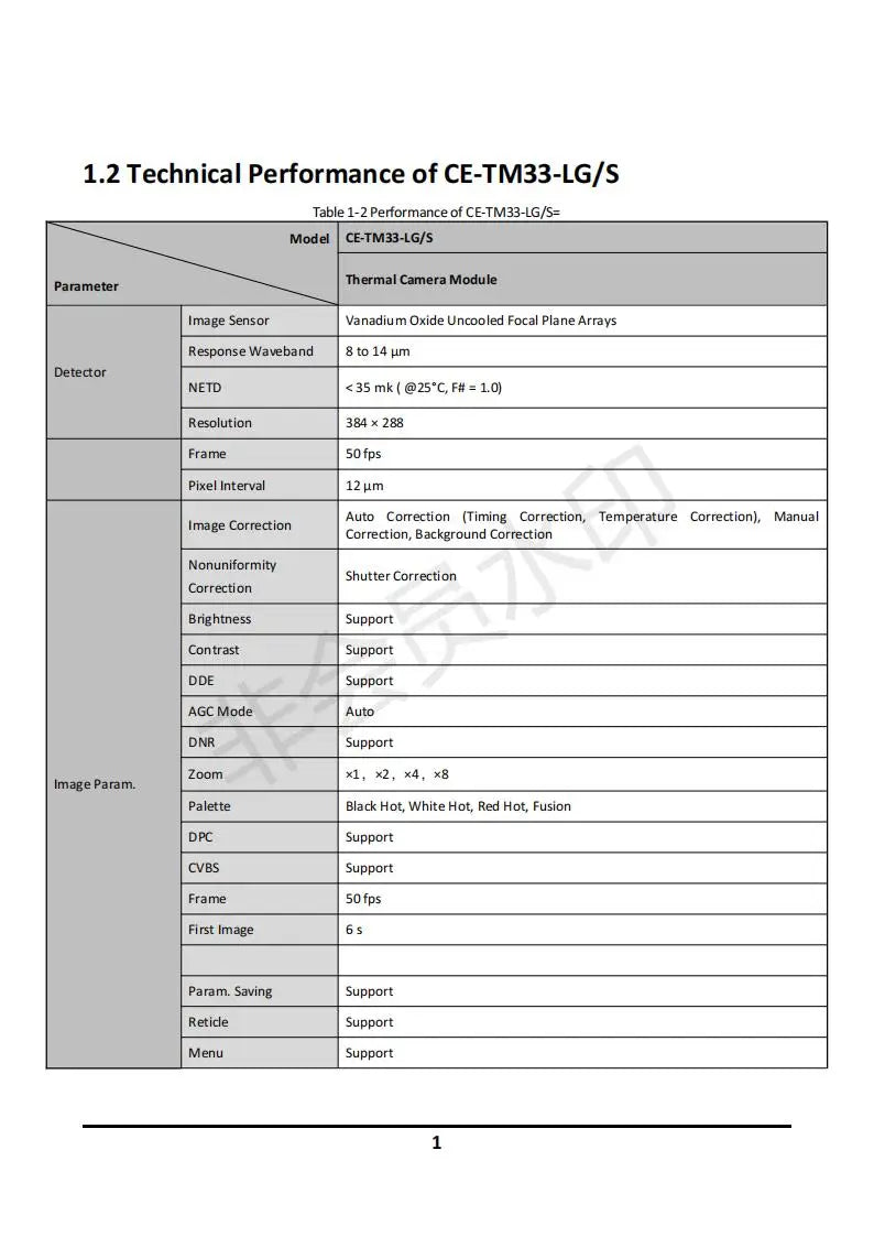
Thermal Camera Module Parmeter Image Sensor Vanadium Oxide Uncooled Focal Plane Arrays Response Waveband 8 to 14 pm Detector NETD 35 mk ( @25'C,F# - 1.0) Resolution 384 288 Frame 50 fps Pixel Interval 12pm Auto Correction (Timing Correction; Temperature Correction); Manual Correction Correction Background Correction Nonuniformity Shutter Correction Correction Brightness Support Contrast Support DDE Support AGC Mode Auto DNR Support Zoom
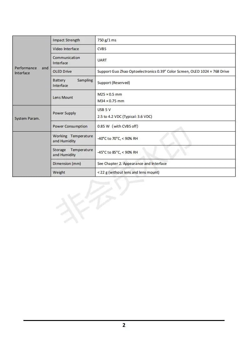
The product features a 0.39-inch color screen, driven by an OLED display with a resolution of 1024x768 pixels. It also supports battery sampling and has a reserved interface for M2S connection. The camera comes with a 0.5mm lens mount and a 0.75mm USB interface that requires a power supply system operating within the range of 2.5 to 4.2 VDC, typically at 3.6 VDC.

The CE-TM33-LG/S model features a bilateral symmetry image plane with a macro-symmetry focal length of M1.6, as well as an M2SXO.5-66 image plane, measuring 7.3mm in height and 16.2mm in width, as depicted in Figure 2-5.
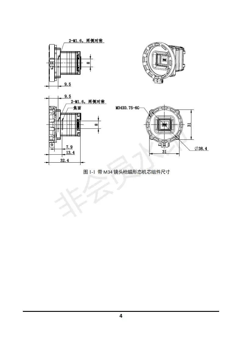
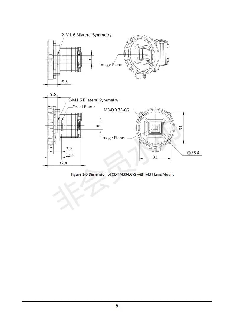
The CE- TM33-LG/S thermal imaging camera has a bilateral symmetry design, featuring a focal plane assembly with a 2-M1.6 lens, an image plane size of M34 x 0.75-66, and physical dimensions of 7.9 cm (height) x 38.4 cm (width) x 13.4 cm (depth).

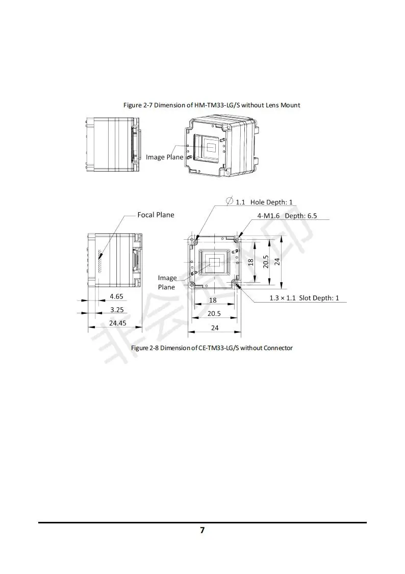
Figure 2-7 Dimension of HM-TM33-LG/S without Lens Mount Image Plane Hole Depth: Focal Plane LM1.6 Depths: 6.5, 4.65, 13*1.1_Slots: 3.25, 20.5, 24.45, 2.85, 2.75, 2.88, 2.95, 2.
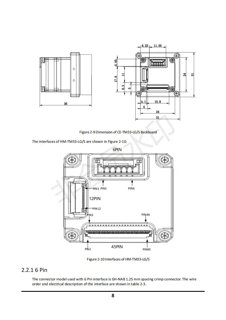
The CVBS interface uses a GH-NAB 1.25mm spacing crimp connector, with pin wiring details and electrical specifications outlined in Table 2-3.
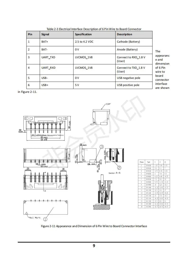
The electrical interface description for the pin wire board connector specifies the following signals: BAT+, which accepts a voltage range of 25 to 42 volts DC and is connected to the cathode (battery); UART_TXD, which uses LVCMOS_Iv8 logic and connects to RXD at 1.8V.

The FPC socket model used with this 12-pin interface is the FH12-125-0.5SH(S5). The wire order and electrical description of the interface can be found in Table 2-4.
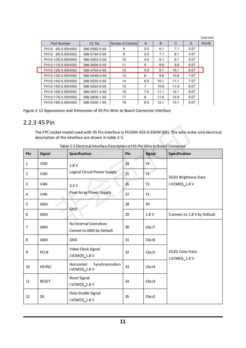
FH12 sshis5) 586-0582-5-55 3.57 FHI? - 85-0 5SHISS) 5586-0744-5-55 35 . Figure 2-12 Appearance and Dimension of 45 Pin Wire to Board Connector Interface 2.2.345 Pin
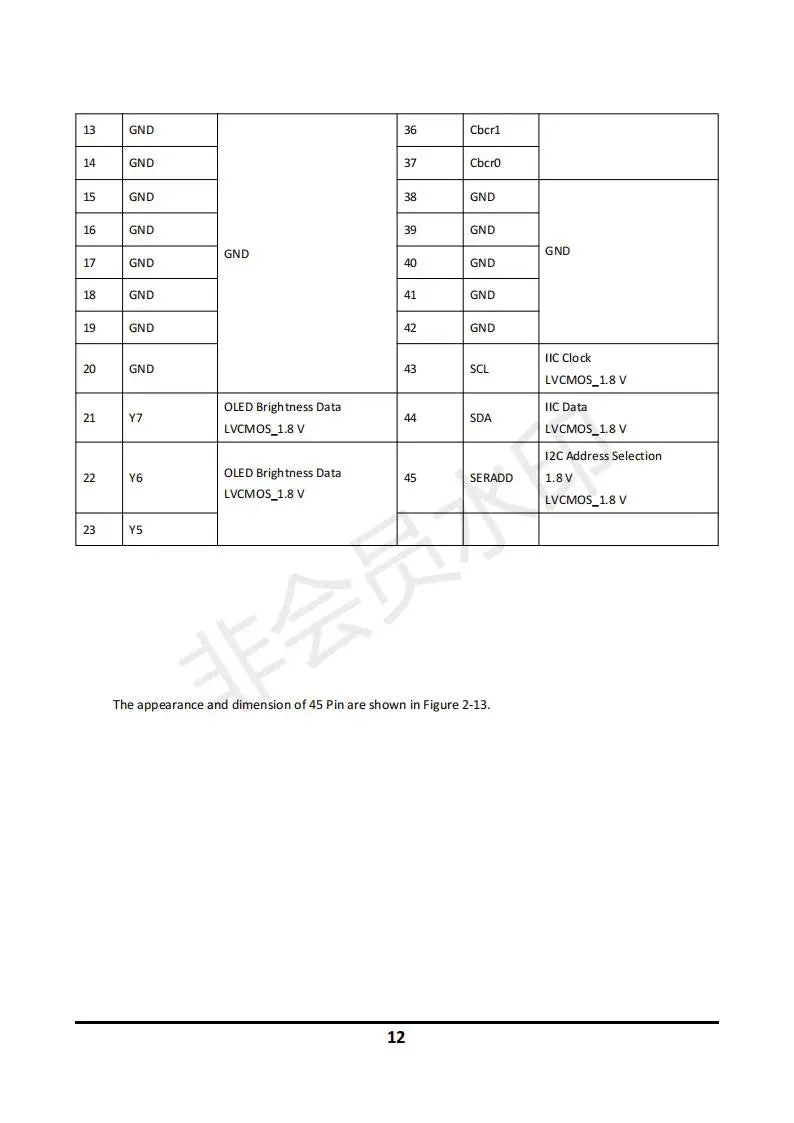
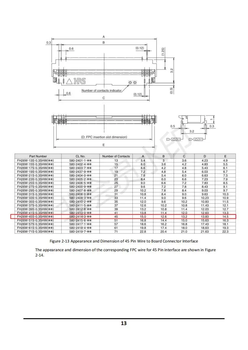
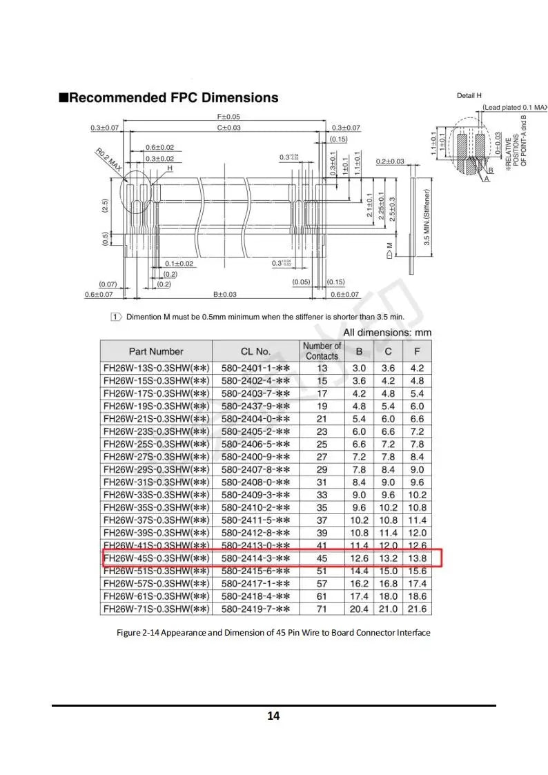
The product specifications include GND, SCL, and LVCMOS18 signals, as shown in Figure 2-13. The 45-pin interface has an appearance and dimension similar to that depicted. Additionally, it features ground (GND), clock (Cbcrl), IZC address selection, OLED brightness data, SERADD with a 1.8V voltage level, compatible with both LVCMOS_1.8V and LVCCMOS_18.
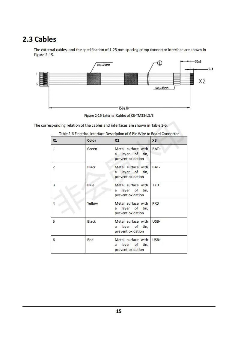
The external cables, as well as the specifications of the 1.25mm spacing crimp connector interface, are depicted in Figure 2-15.
Related Collections


Explore More Drones & Accessories
-

Camera Drone
Our Camera Drone Collection features a wide range of brands including FIMI,...
-
Drone Accessories
Discover a wide range of drone accessories to enhance flight performance, extend...


