CHIHAI CHB-BLDC2418 Mini Brushless DC Motor, 12V / 24V
CHIHAI CHB-BLDC2418 Mini Brushless DC Motor, 12V / 24V
CHIHAI MOTOR
Det gick inte att ladda hämtningstillgänglighet


Overview
The CHIHAI MOTOR CHB-BLDC2418 is a compact permanent-magnet brushless DC motor for small robotics and automatic rotating mechanisms. Its built-in Hall driver supports direction control, PWM speed control and an FG speed-feedback signal through a five-wire connection. Choose a 12V / 4500 rpm or 24V / 9000 rpm configuration with a 6.5, 12 or 21 mm shaft, supplied as a motor alone or with the listed controller and power-supply accessories.
Features
- Compact 310-size motor with approximately 29 g motor weight.
- 2 mm round shaft in three selectable lengths.
- CW/CCW control and PWM speed control with FG pulse feedback.
- Built-in Hall drive electronics; optional external knob controller provides a convenient control interface.
- Three package choices with the original motor, controller and adapter combinations.
Specifications
| Brand / model | CHIHAI MOTOR / CHB-BLDC2418 (310 size) |
|---|---|
| Motor construction | Permanent-magnet brushless DC motor with built-in Hall driver |
| Sale voltage and speed options | 12V / 4500 rpm; 24V / 9000 rpm. Select the matching configuration. |
| Shaft | 2 mm diameter, round; selectable exposed length 6.5, 12 or 21 mm |
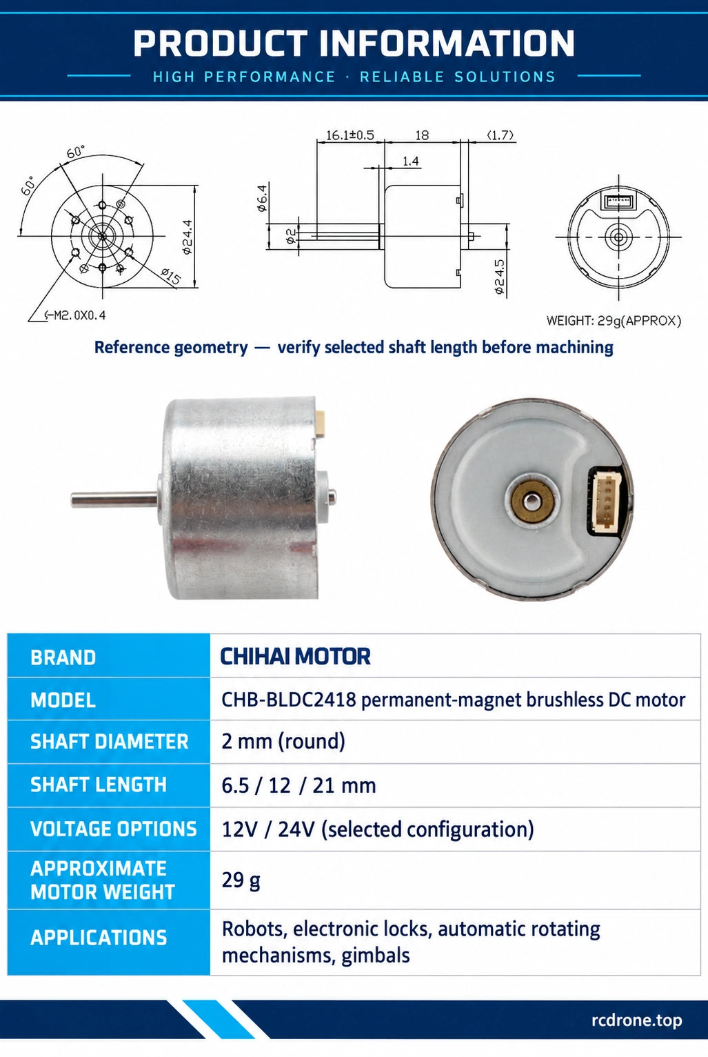
| Body reference | 24.4 mm diameter x 18 mm body length; rear projection (1.7 mm) shown in reference drawing |
| Motor weight | Approximately 29 g; excludes external controller, power adapter and packaging |
| Mounting drawing | 6-M2 x 0.4; 15 mm pitch circle; 60-degree spacing shown; check the actual selected motor before machining |
| Shaft drawing reference | 16.1 ±0.5 mm shaft reference in drawing differs from selectable shaft lengths; do not use it as a promised option length |
| Reference geometry | 1.4 mm step; front boss diameter 6.4 mm; rear shaft reference diameter 2.45 mm |
| Control | Five wires: VCC, GND, CW/CCW, PWM and FG |
| CW/CCW logic | 0–5V input; VIH ≥2.0V, VIL ≤0.5V; high CCW, low CW |
| PWM control | 0–5V; 15–25kHz typical, 60kHz maximum; high ≥2.0V or open = OFF, low ≤0.5V = ON |
| FG speed feedback | Green wire; 6 pulses/cycle, 2mA signal current; VOH 5.0V max, VOL 0.5V max |
24V Performance
The following performance values apply to the 24V / 9000 rpm configuration. They do not describe the 12V option.
| Supply | DC 24.0V |
|---|---|
| No-load current | 0.07A maximum |
| No-load speed | 9000 ±10% rpm |
| Rated torque | 15 g·cm |
| Rated speed | 7750 ±10% rpm |
| Rated current | 0.16A maximum |
| Stall torque | 150 ±10% g·cm |
| Stall current | 0.43 ±10% A |
Stall torque and current are limiting values, not continuous operating ratings. Select the load using rated torque and avoid prolonged stalls. The 4500 rpm speed identifies the 12V sales option; its loaded performance is not specified here.
Wiring and Controller Setup
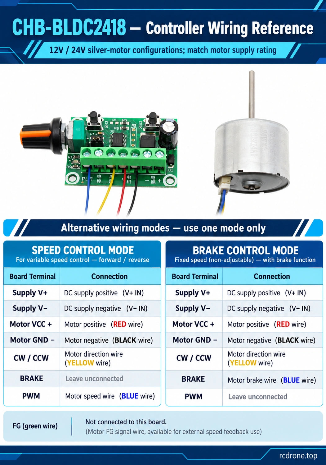
Red is motor VCC, black is GND, yellow selects CW/CCW, blue is PWM and green is FG speed feedback. Match the power supply to the selected 12V or 24V configuration. Do not apply motor supply voltage to the control wires. Removing power stops the motor.
For the optional controller in speed-control mode, connect supply positive/negative to V+/V−, red to motor VCC+, black to motor GND−, yellow to CW/CCW and blue to PWM. Leave BRAKE open. The green FG wire is not connected to this controller.
For the alternative brake-control wiring, retain the same supply, red, black and yellow connections, connect blue to BRAKE and leave PWM open. This mode provides direction and brake control without variable speed. Use one wiring mode at a time.
Mechanical Fit and Operation
Check mounting-hole positions, shaft length and connector clearance on the actual selected configuration before machining a bracket. The dimension drawing is a reference version and includes a 16.1 ±0.5 mm shaft dimension that differs from the three selectable shaft lengths.
Use the correct rated DC voltage and avoid overload or stalled operation. Speed falls as load rises beyond the rated point; reducing motor speed may also reduce available torque. Check the torque requirement at the intended speed. Operating noise varies with speed and load.
Applications
- Small robotic mechanisms requiring compact rotary motion and direction control.
- Electronic lock mechanisms and automatic rotating equipment.
- Compact gimbal and positioning projects where the selected speed, torque and mounting arrangement are suitable.
What's Included
- Motor Only: one selected motor with its five-wire connection lead.
- Motor + Controller: one selected motor with lead and one brushless speed controller.
- Motor + Controller + Power Supply: one selected motor with lead, one controller and one power adapter.
The adapter photograph shows a 24V reference adapter. Check the supplied adapter output label against the selected motor voltage before connection; adapter current, mains input range and regional plug compatibility are not specified. Mounting hardware and application equipment are not included.
FAQ
Does Motor Only include the knob controller?
No. Choose Motor + Controller or Motor + Controller + Power Supply to include it. The motor itself has built-in Hall drive electronics.
Can I use the 24V performance table for the 12V motor?
No. The current, torque and loaded-speed values shown are for the 24V configuration only.
Can the controller read the green FG wire?
The illustrated controller wiring leaves FG unconnected. The motor provides the green feedback wire for a suitable separate signal interface.
Does the reference drawing guarantee the selected shaft length?
No. Choose 6.5, 12 or 21 mm in the configuration selector and verify the actual motor before machining; the drawing depicts a different reference shaft dimension.
Visual Details