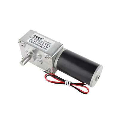
CHIHAI MOTOR CHP-36GP-555 Planetary DC Gear Motor, 12V/24V
CHIHAI MOTOR CHP-36GP-555 Planetary DC Gear Motor, 12V/24V
CHIHAI MOTOR
Det gick inte att ladda hämtningstillgänglighet


Overview
The CHIHAI MOTOR CHP-36GP-555 combines a brushed DC motor with an all-metal planetary gearbox and 8 mm D-shaft. Select 12V or 24V,nominal reduction ratio,and an encoder or non-encoder configuration. Bracket packages add the illustrated36GP mounting bracket. This DC gear motor family supports compatible robot drives and automated mechanisms.
Features
- Metal planetary gearing and ball-bearing-supported shaft construction.
- Optional AB quadrature Hall encoder with 17PPR motor-shaft reference.
- Encoder electronics supplied separately at 3.3V or 5V.
- Distinct motor-only and mounting-bracket packages.
- Reversible brushed DC motor construction.
Specifications
| Specification | Value / scope |
|---|---|
| Family | CHIHAI MOTOR CHP-36GP-555 planetary brushed DC gearmotor |
| Encoder version reference | CHP-36GP-555ABHL with AB quadrature Hall encoder and protective cap |
| Non-encoder versions | Separate motor-only or motor-with-bracket selections;no Hall board/cap/encoder lead promised |
| Selected winding | 12V DC or 24V DC |
| Selected nominal ratios | 3.7:1,5.2:1,14:1,19:1,27:1,51:1,71:1,100:1,139:1,264:1 |
| Gear construction | All-metal planetary reduction gears |
| Shaft/bearing construction | 8 mm D-shaft with ball-bearing support |
| Encoder drawing shaft | 20±0.5 mm projection;15 mm flat-length reference;7 mm flat reference;8 mm diameter(+0/−0.03) |
| Front mounting | Four M3 mounting holes on28 mm pitch-circle reference;maximum screw penetration6 mm |
| Encoder drawing registers | 22 mm front register(+0/−0.05);2 mm shoulder reference |
| Encoder motor dimensions | 36±0.2 mm gearbox diameter;motor envelope37.5 mm maximum;rear section57±0.3 mm;rear cap15.5 mm reference;32 mm cap diameter;34 mm can reference |
| Overall-length scope | 36×114 mm shared encoder assembly reference excluding shaft/terminals;actual length varies with ratio and configuration |
| Encoder motor weight | Approximately480 g;ratio-dependent. No separate non-encoder weight is specified |
| Encoder connector | XH2.54-6PIN with corresponding lead assembly |
| Encoder supply | 3.3V DC or 5.0V DC,independent of12V/24V motor power |
| Encoder output | AB quadrature square waves,17PPR at motor shaft;17×reduction ratio output-shaft pulse reference |
| Encoder electronics | Onboard pull-ups/signal conditioning;100kHz response reference |
| Magnetic ring | 34 poles,17 pole pairs |
| Optional bracket | 36GP L-bracket,50 mm upright,43 mm base,3 mm thickness;weight not specified |
| Bracket interfaces | 28 mm front-hole spacing;22 mm center aperture(+0.10/+0.05);3.2 mm front holes;four M3 andsix3.1 mm base holes;30/43/13/10/20 mm base references;R20 top radius |
| Additional shaft/drawing tolerances | 7 mm flat(+0/−0.10);gearbox length L±0.5 mm |
| External flange-coupler drawing reference,not included | 8 mm bore;32 mm flange diameter;16 mm hub diameter;24 mm hole-pattern reference;four4 mm holes;13 mm length;3 mm flange thickness;8.3 mm shoulder reference;opposed M4 set screws |
Performance References
The tables below are voltage-specific encoder-motor family references. Match the selected winding and ratio. The71:1 selection has no matching column,so no performance,gearbox length or output-PPR value is inferred for it. The515:1 column is a family reference and is not selectable here. Non-encoder packages do not acquire encoder functions from these tables.
24V reference
Maximum power reference 120W;no-load current ≤600mA. Maximum power describes a separate operating point,not continuous output at every ratio.
| Table ratio | No-load rpm | Rated torque(kgf·cm) | Rated torque(N·m) | Rated rpm | Rated current(A) | Stall current(A) | Stall torque(kgf·cm) |
|---|---|---|---|---|---|---|---|
| 3.7:1 | 3200 | 3 | 0.3 | 2400 | ≤2.7 | ≤21 | ≥8.0 |
| 5.2:1 | 2300 | 5 | 0.5 | 1750 | ≤2.7 | ≤21 | ≥10.0 |
| 14:1 | 850 | 10 | 1 | 650 | ≤2.7 | ≤21 | ≥25.0 |
| 19:1 | 630 | 15 | 1.5 | 500 | ≤2.7 | ≤21 | ≥30.0 |
| 27:1 | 440 | 25 | 2.5 | 350 | ≤2.7 | ≤21 | ≥35.0 |
| 51:1 | 230 | 35 | 3.5 | 190 | ≤2.7 | ≤21 | ≥50.0 |
| 100:1 | 120 | 50 | 5 | 90 | ≤2.7 | ≤21 | ≥50.0 |
| 139:1 | 85 | 50 | 5 | 65 | ≤2.7 | ≤21 | ≥50.0 |
| 264:1 | 45 | 50 | 5 | 35 | ≤2.7 | ≤21 | ≥60.0 |
| 515:1 | 23 | 60 | 6 | 18 | ≤2.7 | ≤21 | ≥60.0 |
12V reference
Maximum power reference 30W;no-load current ≤400mA. Maximum power describes a separate operating point,not continuous output at every ratio.
| Table ratio | No-load rpm | Rated torque(kgf·cm) | Rated torque(N·m) | Rated rpm | Rated current(A) | Stall current(A) | Stall torque(kgf·cm) |
|---|---|---|---|---|---|---|---|
| 3.7:1 | 1600 | 1.5 | 0.15 | 1200 | ≤2.0 | ≤10 | ≥4.0 |
| 5.2:1 | 1150 | 2.5 | 0.25 | 850 | ≤2.0 | ≤10 | ≥7.0 |
| 14:1 | 420 | 5 | 0.5 | 320 | ≤2.0 | ≤10 | ≥15.0 |
| 19:1 | 310 | 7.5 | 0.75 | 250 | ≤2.0 | ≤10 | ≥22.0 |
| 27:1 | 220 | 12.5 | 1.25 | 170 | ≤2.0 | ≤10 | ≥25.0 |
| 51:1 | 115 | 17 | 1.7 | 95 | ≤2.0 | ≤10 | ≥35.0 |
| 100:1 | 60 | 30 | 3 | 45 | ≤2.0 | ≤10 | ≥50.0 |
| 139:1 | 42 | 40 | 4 | 32 | ≤2.0 | ≤10 | ≥50.0 |
| 264:1 | 22 | 50 | 5 | 18 | ≤2.0 | ≤10 | ≥60.0 |
| 515:1 | 11.5 | 60 | 6 | 10 | ≤2.0 | ≤10 | ≥60.0 |
Gearbox Length and Encoder Pulse References
| Table ratio | Gearbox L(mm) | Output-shaft pulses/revolution reference |
|---|---|---|
| 3.7:1 | 26.5 | 62.9 |
| 5.2:1 | 26.5 | 88.4 |
| 14:1 | 34.5 | 238 |
| 19:1 | 34.5 | 323 |
| 27:1 | 34.5 | 459 |
| 51:1 | 42.5 | 867 |
| 100:1 | 42.5 | 1700 |
| 139:1 | 42.5 | 2363 |
| 264:1 | 50.5 | 4488 |
| 515:1 | 50.5 | 8755 |
Pulse references use17PPR multiplied by the nominal table ratio. Quadrature edge counting depends on the host's counting method and is not the same as this single-channel pulse reference. Stall values are limiting references;avoid stalled or overloaded operation.
Encoder Wiring
The following six-pin mapping applies only to encoder versions. Identify connector orientation against the complete dimensioned drawing and wire colors. Motor power and encoder power use separate pins. Never connect12V or 24V motor power to encoder VCC.
| Pin | Signal | Wire color | Function |
|---|---|---|---|
| 1 | M2 | White | Motor supply− |
| 2 | VCC | Blue | Encoder supply+3.3V/5V |
| 3 | C2 | Green | Encoder phase B |
| 4 | C1 | Yellow | Encoder phase A |
| 5 | GND | Black | Encoder supply− |
| 6 | M1 | Red | Motor supply+ |
The encoder provides A/B square waves with onboard pull-ups and signal conditioning. Match the host's logic voltage,ground reference and input capability. The simple illustration is presented with the same C2/B and C1/A mapping as the six-pin table.
Mechanical Installation
Check output-shaft fit,front register,28 mm mounting pattern and ratio-dependent gearbox length. Maximum M3 screw penetration is 6 mm. The encoder drawing includes the rear Hall assembly and protective cap;non-encoder versions have a different rear assembly. Do not transfer the encoder assembly's total length to a non-encoder motor.
The bracket drawing shows a 50 mm upright,a 43 mm base and 3 mm thickness,with a 22 mm central aperture and multiple mounting holes. The8 mm bore flange-coupler illustration is an external fit reference only;a flange coupler is not included in the selectable packages. Smaller-bore couplers must not be assumed to fit the 8 mm shaft.
Applications
Compatible self-balancing vehicles,small smart vehicles,robotic mechanisms,grippers and motorized film-cutting mechanisms where the selected speed,torque,supply and mounting fit the application. Encoder feedback is available only on encoder selections.
What's Included
| Selected configuration | Contents |
|---|---|
| Encoder Motor | 1 encoder-equipped gearmotor and corresponding six-wire lead assembly |
| Encoder Motor + Mounting Bracket | 1 encoder-equipped gearmotor,corresponding lead assembly and 1 mounting bracket |
| Non-Encoder Motor | 1 non-encoder gearmotor |
| Non-Encoder Motor + Bracket | 1 non-encoder gearmotor and 1 mounting bracket |
A motor driver,power supply,host controller and flange coupler are not included. Non-encoder versions do not include the Hall encoder,protective cap or encoder lead assembly.
FAQ
Can the encoder be powered from the 12V or 24V motor supply?
No. Encoder VCC requires 3.3V or 5V. Motor power uses the separate M1/M2 pins.
Is17PPR measured at the gearbox output?
It is the motor-shaft base pulse reference. The output reference is 17 multiplied by the reduction ratio;the host's quadrature counting method is separate.
Where are the 71:1 performance figures?
No matching71:1 column is provided. Another ratio's values must not be substituted.
Does the non-encoder version have the same rear cap and cable?
No. Its rear assembly differs and it does not include the Hall board,encoder cap or six-wire encoder lead assembly.
Is the flange coupler included?
No. The8 mm coupler image is a mechanical fit reference. Selectable accessory packages add only the named mounting bracket.
Visual Details