CHIHAI CHS-GM37BY Geared Stepper Motor, 2-Phase 4-Wire, 12V
CHIHAI CHS-GM37BY Geared Stepper Motor, 2-Phase 4-Wire, 12V
CHIHAI MOTOR
Det gick inte att ladda hämtningstillgänglighet


Overview
The CHIHAI MOTOR CHS-GM 37BY is a 37 mm geared stepper motor with two-phase, four-wire bipolar operation and a 6 mm D-shaped output shaft. Select one of ten reduction ratios and a motor-only or mounting-bracket package for compact positioning mechanisms.
Features
- Metal gears and copper motor winding.
- Discrete step control and reversible rotation through a compatible bipolar stepper driver.
- D-shaped shaft and six front mounting holes.
- Matching four-pin lead, with optional mounting bracket.
Specifications
| Brand / model | CHIHAI MOTOR / CHS-GM 37BY-30Ω; GM 37BY geared stepper family |
| Motor | Two-phase, four-wire permanent-magnet bipolar stepper, metal reduction gears, copper winding |
| Rated motor reference | 12 V DC; 0.4 A per phase; 30Ω ±15% per phase |
| Input step angle / excitation | 7.5 degrees per step; two-phase excitation, bipolar drive |
| Input pull-out / holding torque | At least 300gf.cm pull-out; at least 600gf.cm holding at 0PPS |
| Frequency reference | Maximum response 750PPS/Hz; maximum starting 700PPS/Hz |
| Insulation | ClassE coils; 100MΩ at 500VDC; 100VAC for one second dielectric reference |
| Operating temperature | -10 to +55 degreesC |
| Shaft / front | 6 mm D shaft +0/-0.03 mm; 5.4 mm flat +0/-0.1 mm; 21±0.5 mm projection, 12 mm flat, 12 mm front boss and 6 mm shoulder |
| Mounting | Six M 3.0 x 3 tapped holes on 31 mm circle; 7 mm reference; drawing 6-120degree notation retained in original frontview |
| Body drawing | 37 mm gearbox; L±0.3 mm, 22.2 mm MAX motor body, 35 mm rear envelope, 10 mm rear feature and 1.5 mm section |
| Cable / connector | SM-4PIN; UL 1007 AWG 26; 150±10 mm lead; 12.9 mm rear connector width and 6 mm reference |
| Mass | Approximately 165–200 g motor reference, ratio dependent |
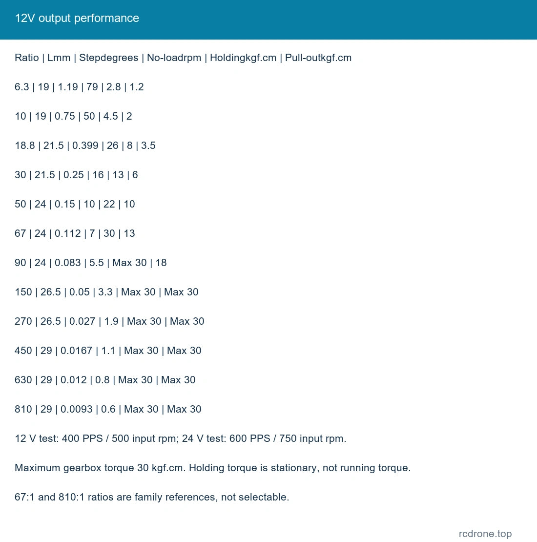
Output Performance at 12 V
Test condition: 12 V DC, 400PPS/Hz, input motor 500 rpm. Holding torque is a stationary value and differs from pull-out torque while stepping.
| Ratio : 1 | Gearbox Lmm | Output step degrees | No-load rpm | Holding kgf.cm | Pull-out kgf.cm |
|---|---|---|---|---|---|
| 6.3 | 19 | 1.19 | 79 | 2.8 | 1.2 |
| 10 | 19 | 0.75 | 50 | 4.5 | 2 |
| 18.8 | 21.5 | 0.399 | 26 | 8 | 3.5 |
| 30 | 21.5 | 0.25 | 16 | 13 | 6 |
| 50 | 24 | 0.15 | 10 | 22 | 10 |
| 67 | 24 | 0.112 | 7 | 30 | 13 |
| 90 | 24 | 0.083 | 5.5 | Max 30 | 18 |
| 150 | 26.5 | 0.05 | 3.3 | Max 30 | Max 30 |
| 270 | 26.5 | 0.027 | 1.9 | Max 30 | Max 30 |
| 450 | 29 | 0.0167 | 1.1 | Max 30 | Max 30 |
| 630 | 29 | 0.012 | 0.8 | Max 30 | Max 30 |
| 810 | 29 | 0.0093 | 0.6 | Max 30 | Max 30 |
Output Performance at 24 V
Test condition: 24 V DC, 600PPS/Hz, input motor 750 rpm. Use an appropriate driver and current limits; 24 V is a test/drive condition rather than a second selectable motor winding.
| Ratio : 1 | Gearbox Lmm | Output step degrees | No-load rpm | Holding kgf.cm | Pull-out kgf.cm |
|---|---|---|---|---|---|
| 6.3 | 19 | 1.19 | 119 | 3.5 | 2 |
| 10 | 19 | 0.75 | 75 | 5.5 | 3.2 |
| 18.8 | 21.5 | 0.399 | 40 | 10 | 5.8 |
| 30 | 21.5 | 0.25 | 25 | 16.5 | 9 |
| 50 | 24 | 0.15 | 15 | 25 | 15 |
| 67 | 24 | 0.112 | 11 | Max 30 | 20 |
| 90 | 24 | 0.083 | 8.3 | Max 30 | 28 |
| 150 | 26.5 | 0.05 | 5 | Max 30 | Max 30 |
| 270 | 26.5 | 0.027 | 2.7 | Max 30 | Max 30 |
| 450 | 29 | 0.0167 | 1.7 | Max 30 | Max 30 |
| 630 | 29 | 0.012 | 1.2 | Max 30 | Max 30 |
| 810 | 29 | 0.0093 | 0.9 | Max 30 | Max 30 |
Maximum permitted gearbox torque 30kgf.cm. Ratios 67: 1 and 810: 1 are family references and are not selectable. Do not use a stationary holding figure as continuous running torque.
Drive and Resonance Reference
The motor is rated at 12 V. The 3.7–24 V drive references below were measured using full-step excitation and a stepper-motor tester without current limiting. They describe operating-window tests, not recommended continuous phase-current settings. Use a suitable bipolar driver, current limiting and thermal checks; do not apply DC directly across a winding. Operating frequency should avoid resonance and excessive vibration.
| Test supply | Upper frequency Hz / test current | Input rpm at upper | Lower frequency Hz / test current | Input rpm at lower | Locked current at 0Hz |
|---|---|---|---|---|---|
| 24 V | 670 / ≤0.12 A | 837.5 | 550 / ≤0.16 A | 687.5 | 1.5 A |
| 12 V | 460 / ≤0.07 A | 575 | 330 / ≤0.10 A | 412.5 | 0.78 A |
| 6 V | 280 / ≤0.06 A | 350 | 200 / ≤0.16 A | 250 | 0.4 A |
| 3.7 V | 150 / ≤0.06 A | 187.5 | 60 / ≤0.15 A | 75 | 0.25 A |
Four-Wire Connection
| Pin | Wire | Phase |
|---|---|---|
| 1 | Yellow | A |
| 2 | Black | B |
| 3 | Red | B-bar |
| 4 | Green | A-bar |
Yellow/green form the A winding; black/red form the B winding. Keep each coil pair on one driver phase. Reverse the excitation order to reverse rotation. The rotation reference is viewed from the flange side. The four-state, two-phase-on sequence is yellow+black, yellow+red, green+red, green+black; reverse the order for the opposite direction. Disconnect power before changing connections.
Mechanical Fit
| Ratio group | Gear stages | Gearbox Lmm | Body length excluding output shaft mm | Backlash reference degrees |
|---|---|---|---|---|
| 6.3 /10 | 2 | 19 | 41.2 | 0.7 |
| 18.8 /30 | 3 | 21.5 | 43.7 | 0.8 |
| 50 /67 /90 | 4 | 24 | 46.2 | 1.0 |
| 150 /270 | 5 | 26.5 | 48.7 | 1.0 |
| 450 /630 /810 | 6 | 29 | 51.2 | 1.0 |
Check shaft projection, flat, mounting holes, screw depth and cable clearance before installation. Keep screws clear of internal gears and allow for gearbox backlash in positioning. The bracket references 40 mm width, 47 mm height, 43 mm foot length, 3 mm thickness, 13 mm slotted opening withR 6.5 end, 31 mm front-hole circle withsix 3.2 mm holes, 14 mm and 18.5 mm front features, four 3.6 mm base holes spaced 30x 24 mm and 8 mm edge offset.
Applications
Small robot mechanisms, positioning experiments, line-following or balancing-vehicle development, camera-jib motion and compact motorized fixtures where the chosen step rate, torque, backlash and shaft fit the application. A complete vehicle, robot or motion platform is not included.
What's Included
- Motor Only: one selected-ratio geared stepper motor with four-wire lead.
- Motor + Bracket: one selected motor/lead and one mounting bracket.
A programmable controller, driver board and power supply are not included in either selectable package. Controller images show optional integration examples only.
FAQ
Does this motor run from a direct 12 V connection?
No. Use a compatible bipolar stepper driver to energize the two winding pairs in sequence.
Is a programmable driver included?
No. The selectable packages contain the motor, or motor and bracket.
Can holding torque be used as running torque?
No. Use the pull-out torque at the intended stepping condition, and stay within the 30kgf.cm gearbox limit.
Visual Details