Kunwei KWR36 Six-Axis Force/Torque Sensor, 36 mm, 30–500 N for Robotics
Kunwei KWR36 Six-Axis Force/Torque Sensor, 36 mm, 30–500 N for Robotics
Kunwei Sensing
Det gick inte att ladda hämtningstillgänglighet


Overview
The Kunwei KWR36 six-axis force/torque sensor measures three forces and three moments in a compact 36 mm body for robotic contact-force control, precision assembly and research. Four model choices provide force capacities from 30 to 500 N and torque capacities from 1.5 to 9 N·m per axis. Strain-gauge measurement and six-axis joint calibration support accurate multi-axis sensing; digital communication is provided through a matched external acquisition module.
Features
- Simultaneous Fx, Fy, Fz and Mx, My, Mz measurement.
- Four model-specific load ranges in the same nominal 36 mm series format.
- Six-axis joint calibration to reduce cross-axis interference.
- 0.5% FS accuracy, 0.1% FS repeatability and 300% FS overload level.
- Compact installation for robot tooling and space-constrained measurement fixtures.
- Analog sensor signals processed through compatible acquisition electronics for the required digital interface.
Specifications
| Parameter | KWR36A | KWR36B | KWR36C | KWR36G |
|---|---|---|---|---|
| Range Fx, Fy (N) | 30 | 50 | 80 | 500 |
| Range Fz (N) | 30 | 50 | 80 | 500 |
| Range Mx, My (Nm) | 1.5 | 2 | 3 | 9 |
| Range Mz (Nm) | 1.5 | 2 | 3 | 9 |
| Diameter (mm) | 36 | 36 | 36 | 36 |
| Height (mm) | 21 | 21 | 21 | 21 |
| Material | Aluminum Alloy | Aluminum Alloy | Aluminum Alloy | Confirm selected configuration |
| Surface Finish | Anodized | Anodized | Anodized | Electropolished |
| Overload Level (%FS) | 300 | 300 | 300 | 300 |
| Resolution (%FS) | 0.03 | 0.03 | 0.03 | 0.03 |
| Repeatability (%FS) | 0.1 | 0.1 | 0.1 | 0.1 |
| Accuracy* (%FS) | 0.5 | 0.5 | 0.5 | 0.5 |
| Weight (kg) | 0.04 | 0.05 | 0.06 | 0.16 |
| Protection Rating | IP64 | IP64 | IP64 | IP64 |
| Operating Temperature (°C) | +5 to +80 (documented A/B/C setup) | +5 to +80 (documented A/B/C setup) | +5 to +80 (documented A/B/C setup) | Confirm selected configuration |
| Sampling Rate (Hz) | 1000 | 1000 | 1000 | Match the selected acquisition configuration |
| Matched acquisition module supply (VDC) | 9–24 (documented RS422/RS485 module) | 9–24 (documented RS422/RS485 module) | 9–24 (documented RS422/RS485 module) | Match the selected module |
| Communication Interface | Via matched module: RS422/RS485/Modbus/CAN/CAN FD/TCP/UDP/EtherCAT/USB; configuration dependent | |||
FS means full scale. The listed force and moment capacities apply to the corresponding sensor axes, not robot payload. Consider tool mass, lever arms and combined loads when selecting a model. Overload level is not a continuous operating range.
Body masses are sensor specifications, not packed shipping weights. Nominal height is 21 mm; a 20 mm mechanical version is also documented. Electrical ratings and sampling performance depend on the matched acquisition setup. A/B/C manuals specify 24-bit acquisition and 1 kHz sampling; ADC bit depth and the listed 0.03% FS resolution describe different characteristics.
Acquisition and Communication
The sensor's analog strain signals require matched acquisition electronics. RS485 and RS422 measurement packages use an external module; other available module configurations support the interfaces listed above. Selecting KWR36A, B, C or G selects the load range, not every communication protocol simultaneously.
| Documented RS485 / RS422 module supply | 9–24 VDC |
|---|---|
| Module power | Less than 3 W |
| Documented serial settings | 460800 baud; 8 data bits; 1 stop bit; no parity |
| Sensor/module connection | DB25 or HDB15, depending on configuration |
| Acquisition module reference | KWH06C80NL series in the RS485/RS422 manuals |
Power the matched module according to its rating; do not apply a generic series voltage directly to unidentified sensor leads. Use the protocol, connector assignment and engineering-unit conversion in the matching manual. Serial data values must not be assumed to be in newtons simply because the capacity table uses N.
Applications
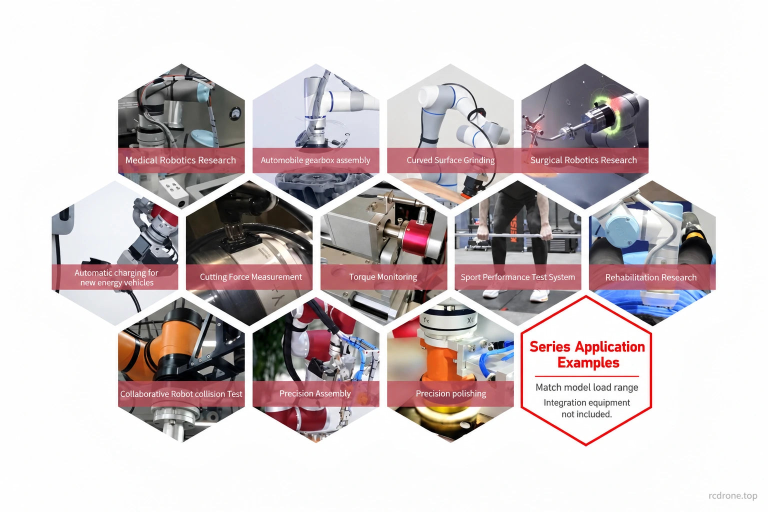
- Precision insertion and assembly: monitor contact forces and moments as parts engage.
- Robotic grinding and polishing: provide multi-axis load feedback for contact-control development.
- Tooling, gearbox assembly and torque-monitoring fixtures within the selected model's capacities.
- Robot interaction and collision-load research, including humanoid, exoskeleton, quadruped and guided-vehicle integration where the load envelope is suitable.
- Biomechanics, rehabilitation and medical-robotics research requiring compact force measurement.
Application images illustrate series-level integration examples, not verified compatibility with every machine shown. They do not establish clinical approval or a complete robot safety function.
Mechanical Installation and Calibration
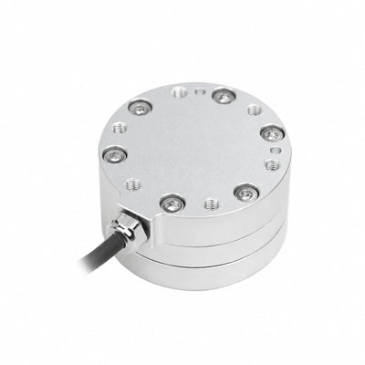
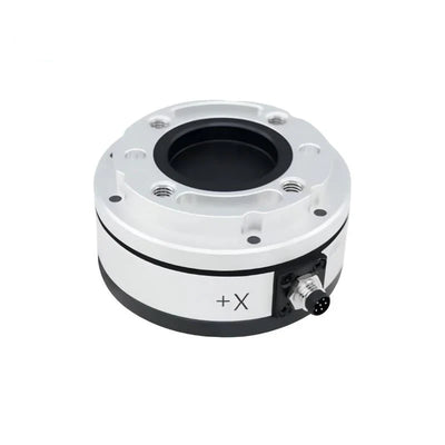
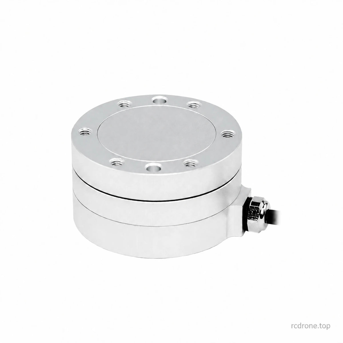
The 36 mm body has distinct tool-side and mounting-side interfaces. Mechanical references cover a 20 mm body with face-specific M3 threads and a separate 21 mm drawing with M4 threads. Both show a nominal 30 mm mounting circle. Match the actual unit's drawing, screw depth, locating holes and angular orientation before machining an adapter; the drawings are not interchangeable.
Secure the designated mounting faces without opening the calibrated sensing body, provide cable strain relief and avoid unintended installation loads. Zero the installed measurement system and account for tool weight and orientation before measurement. Use the selected configuration's environmental limits; the documented A/B/C setup specifies +5 to +80 °C.
What's Included
- 1 × Kunwei KWR36 sensor in the selected A, B, C or G model.
- Electronic product documentation available below.
The documented RS485/RS422 package also lists one data acquisition module and a package box. Confirm the module/interface configuration for the selected model, especially KWR36G, before integration. The sensor model options alone do not specify a digital interface. Robot arms, end effectors, power supplies, host adapters and application fixtures are not listed as package contents.
Downloads
- KWR36 mechanical drawing (PDF)
- KWR36 RS485 user manual (PDF)
- KWR36 RS422 user manual (PDF)
- Kunwei six-axis sensor selection manual (PDF)
FAQ
Which KWR36 model should I choose?
Compare both force and moment loads: A is 30 N / 1.5 N·m, B 50 N / 2 N·m, C 80 N / 3 N·m and G 500 N / 9 N·m per axis. Include tool weight and lever-arm moments when checking the load envelope.
Can I connect the bare sensor directly to RS485, CAN or EtherCAT?
Digital communication requires the matching acquisition module. The model letters select measuring ranges; the interface depends on the module configuration.
Is an acquisition module included?
The RS485/RS422 package documentation lists a sensor, one acquisition module, an electronic manual and a box. Check the module/interface configuration for your selected model, especially KWR36G.
Can I use the same mounting adapter for every KWR36 drawing?
Confirm the actual unit before machining: available references include 20 mm/M3 and 21 mm/M4 versions. Match locating holes, thread depths and mounting orientation as well as the diameter.
Does 300% overload mean I can measure three times the rated load?
No. Select a model whose rated force and moment ranges cover the working loads; the overload figure does not extend the specified measuring range.
Visual Details