

WitMotion JY-RM3100 Seriell 3-axlig elektronisk kompassmodul (PNI RM3100) Riktvinkel TTL/SPI/IIC
WitMotion JY-RM3100 Seriell 3-axlig elektronisk kompassmodul (PNI RM3100) Riktvinkel TTL/SPI/IIC
WitMotion
Det gick inte att ladda hämtningstillgänglighet


Översikt
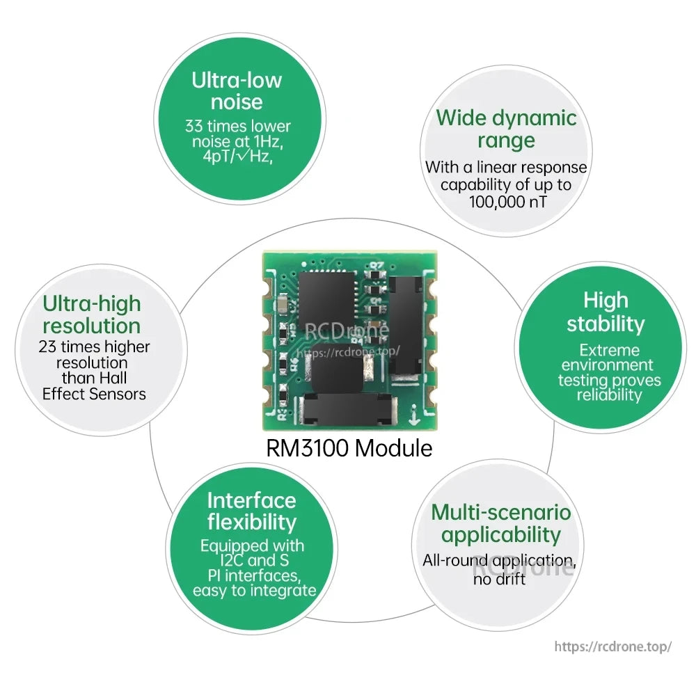
WitMotion JY-RM3100 är en seriell 3-axlig elektronisk kompass (geomagnetisk sensor) modul baserad på en PNI RM3100 magnetisk sensorslösning, utformad för att leverera 3-axlig magnetfältdata och en riktvinkel. Den använder fluxgate-teknik och stöder flera gränssnitt för integration i robotik, UAV/RC-navigering och andra projekt för riktning/attitydssensorer.
Nyckelfunktioner
- Hög känslighet 3-axlig mätning av magnetfält med utgång för riktvinkel
- Fluxgate-teknologi
- Flera gränssnitt: TTL / SPI / IIC
- Magnetfältets självåterställning
- Stämpelhål (kapslad) paketstil ("halv hål av stämpelhål")
- Inbyggd MCU för datainsamling (modulfunktion)
- AT-serieport stöd (modulfunktion)
- Beräkning av riktvinkel (modulfunktion)
- Kalibrering av magnetfältets nollbias (modulfunktion)
Specifikationer
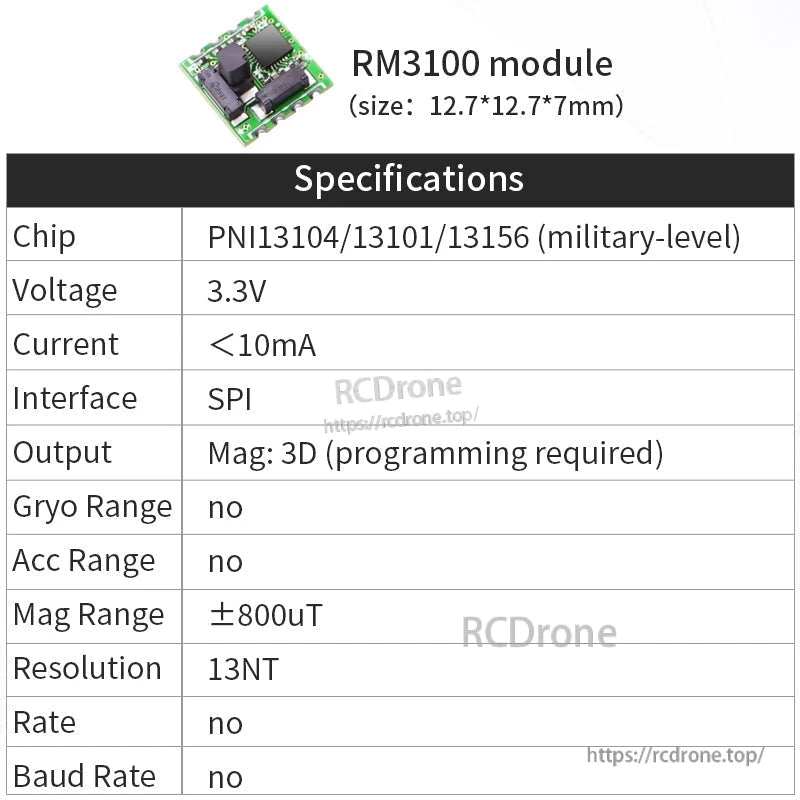
Modellparameter tabell (som tillhandahålls)
| Parameter | QMC5883L | JY-RM3100 | RM3100 (Ingen programvara) |
|---|---|---|---|
| Driftspänning (ström) | 3.3-5V (<5mA) | 3.3-5V (<6mA) | 3.3-5V (<6mA) |
| Utdata | 3-axlig magnetometer, kursvinkel | 3-axlig magnetometer, kursvinkel | 3-axlig magnetometer |
| Område | ±8 Gauss | ±800uT | ±800uT |
| Returfrekvens | 0.1-100Hz | 1-100Hz | 0.1-100Hz |
| Kommunikationsmetod | TTL/SPI/IIC | TTL/SPI/IIC | SPI |
| Baudrate | 9600 (standard); 115200, 460800 | 9600 (standard); 115200, 460800 | 9600 (standard); 115200, 460800 |
| Känslighet | 3000 LSB/Gauss | 13nT/LSB | 13nT/LSB |
| Driftstemperatur | -40 till 85°C | -40 till 85°C | -40 till 85°C |
| Läge | ASCII/Modbus/Modbus Auto utdata | ASCII/Modbus | \ |
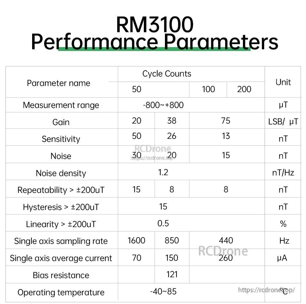
RM3100 Prestandaparametrar (Cykelräkningar 50 / 100 / 200)
| Parameternamn | 50 | 100 | 200 | Enhet |
|---|---|---|---|---|
| Mätningsområde | -800~+800 | -800~+800 | -800~+800 | uT |
| Vinst | 20 | 38 | 75 | LSB/uT |
| Känslighet | 50 | 26 | 13 | nT |
| Brus | 30 | 20 | 15 | nT |
| Brusdensitet | 1.2 | nT/Hz | ||
| Reproducerbarhet > ±200uT | 15 | 8 | 8 | nT |
| Hysteres > ±200uT | 15 | nT | ||
| Linjäritet > ±200uT | 0.5 | % | ||
| Enaxlig provtagningsfrekvens | 1600 | 850 | 440 | Hz |
| Enaxlig genomsnittlig ström | 70 | 150 | 260 | uA |
| Biasmotstånd | 121 | |||
| Drifttemperatur | -40~85 | |||
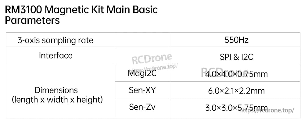
RM3100 Magnetkit Huvudparametrar
| 550Hz | |
| Gränssnitt | SPI & I2C |
| Mått (längd x bredd x höjd) - MagI2C | 4.0 x 4.0 x 0.75mm |
| Mått (längd x bredd x höjd) - Sen-XY | 6.0 x 2.1 x 2.2mm |
| Mått (längd x bredd x höjd) - Sen-Zv | 3.0 x 3.0 x 5.75mm |
Ytterligare text specifikationer visas
- RM3100 SPI mätområde: ±800uT
- JY-RM3100 mätområde: ±800uT
- QMC5883L mätområde: ±8 Gauss
- Mätbrus är mindre än 15uT @ 200 cykelräkningar
- Mätupplösning är högre än 13uT @ 200 cykelräkningar
Mått
JY-RM3100 modulmått (som visas)
- 15.24mm x 15.24mm
- 12.7mm (visas på ritning)
- 2.54mm (visas på ritning)
- 0.9mm (visas på ritning)
- Tjocklek: 7.35mm
RM3100 modulmått (som visas)
- Storlek: 12.7mm x 12.7mm
- Tjocklek: 7.4mm
- Ytterligare markerade mått: 2.45mm, 2.63mm, 2.40mm, 2.68mm, 2.54mm, 7.62mm
QMC5883L modulmått (som visas)
- 15.24mm x 15.24mm
- 12.7mm (visas på ritningen)
- 2.54mm (visas på ritningen)
- 0.9mm (visas på ritningen)
- Tjocklek: 2mm
Kablar / Pinout
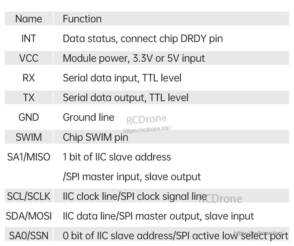
JY-RM3100 Pin-namn och funktioner
| Namn | Funktion |
|---|---|
| INT | Data status, anslut chip DRDY pin |
| VCC | Modulens strömförsörjning, 3.3V eller 5V ingång |
| RX | Seriell datainmatning, TTL-nivå |
| TX | Seriell datautgång, TTL-nivå |
| GND | Jordlinje |
| SWIM | Chip SWIM-stift |
| SA1/MISO | 1 bit av IIC slavadress / SPI masteringång, slavutgång |
| SCL/SCLK | IIC klocklinje / SPI klocksignal linje |
| SDA/MOSI | IIC datalinje / SPI masterutgång, slavingång |
| SA0/SSN | 0 bit av IIC slavadress / SPI aktiv låg selekteringsport |
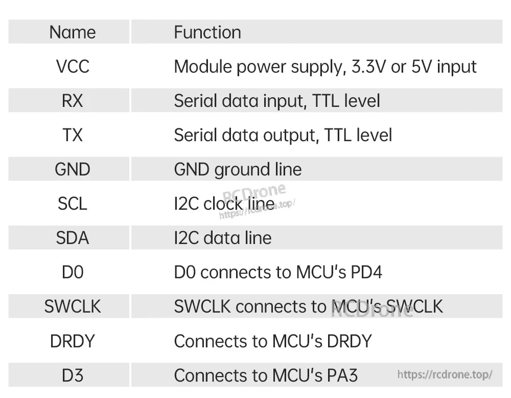
QMC5883L Stift Namn och Funktioner
| Namn | Funktion |
|---|---|
| VCC | Modulens strömförsörjning, 3.3V eller 5V ingång |
| RX | Seriell datainmatning, TTL-nivå |
| TX | Seriell datautgång, TTL-nivå |
| GND | GND jordlinje |
| SCL | I2C klocklinje |
| SDA | I2C datalinje |
| D0 | D0 ansluts till MCU:s PD4 |
| SWCLK | SWCLK ansluts till MCU:s SWCLK |
| DRDY | Ansluts till MCU:s DRDY |
| D3 | Ansluts till MCU:s PA3 |
RM3100 Modul Pad Etiketter (som visas)
- VCC, GND, GND, DRDY
- CLK, MISO, MOSI, SSN
Demo / Datavisning
- Seriell kommunikation; PC-programvara visar data i realtid.
- Visade fält inkluderar: Magnetisk X, Magnetisk Y, Magnetisk Z, Gyration.
Anteckningar
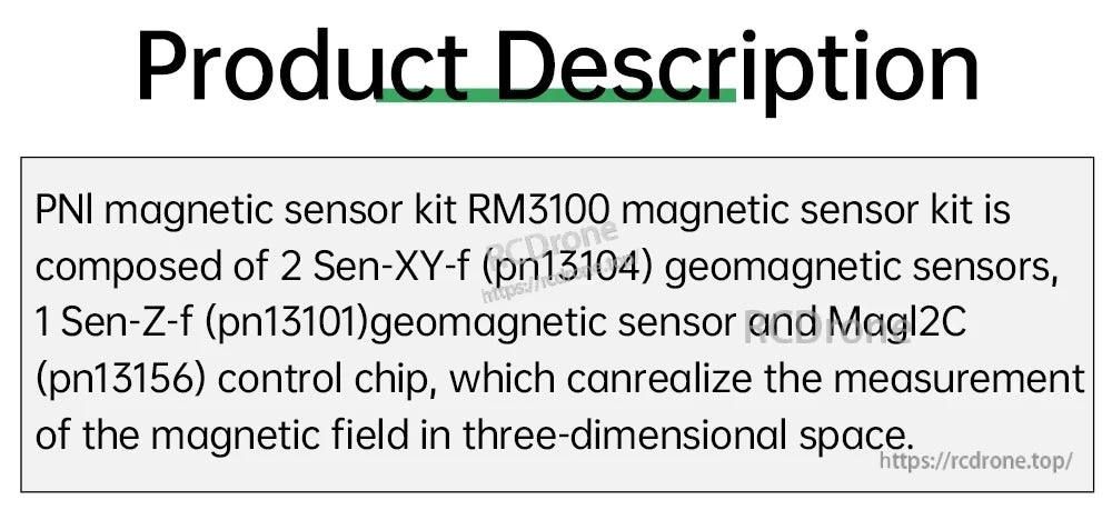
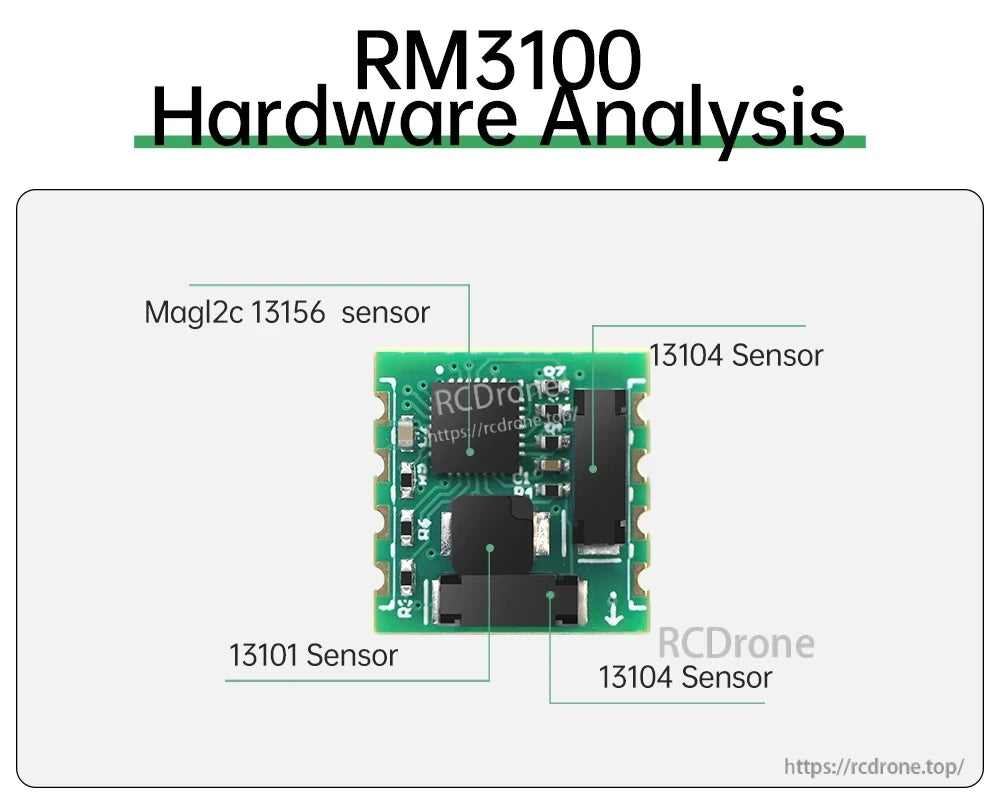
- RM3100 magnetiska sensor kit sammansättning (som tillhandahålls): 2 x Sen-XY-f (pn13104), 1 x Sen-Z-f (pn13101), och MagI2C (pn13156) kontrollchip, för 3D magnetfältmätning.
- Prestandajämförelsedata visas (Hall-sensor vs PNI magnetisk sensor): Känslighet 300nT vs 13nT; Brus 500nT vs 15nT; Strömförbrukning (8Hz, 3 axlar) 280uA vs 70uA.
- För val/kompatibilitetsfrågor (JY-RM-3100 eller RM3100 alternativ) och integrationssupport, kontakta [email protected] or besök https://rcdrone.top/ .
Detaljer
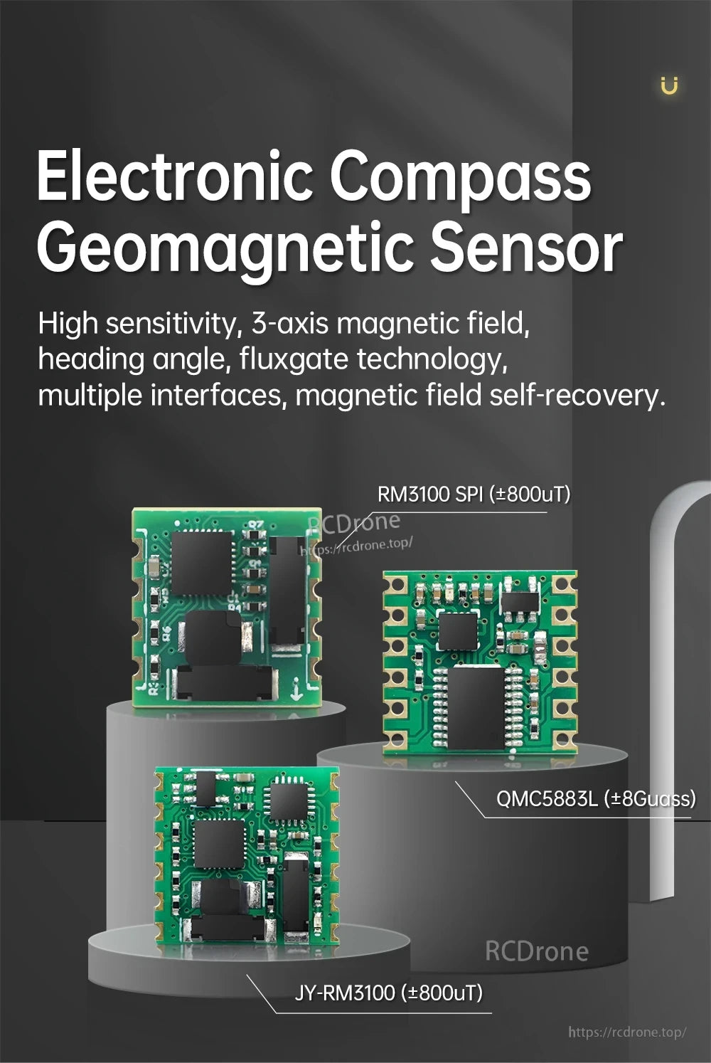
JY-RM3100-modulen använder en PNI RM3100 fluxgate magnetisk sensor för att utdata 3-axlig magnetfältdata och en beräknad kursvinkel.
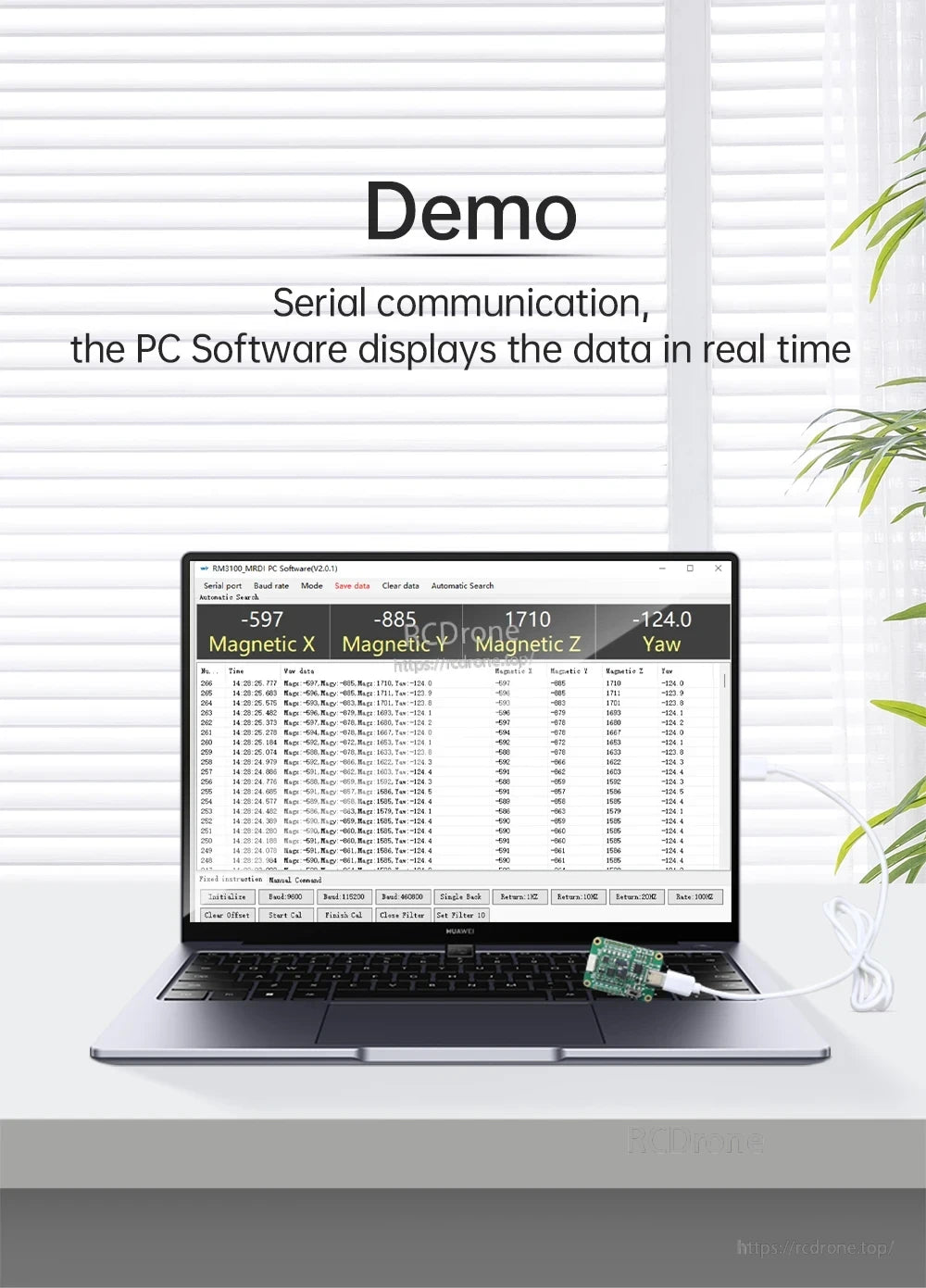
Realtidsserielutdata gör det enkelt att verifiera Magnetisk X/Y/Z avläsningar och gyration på en dator under installation och kalibrering.
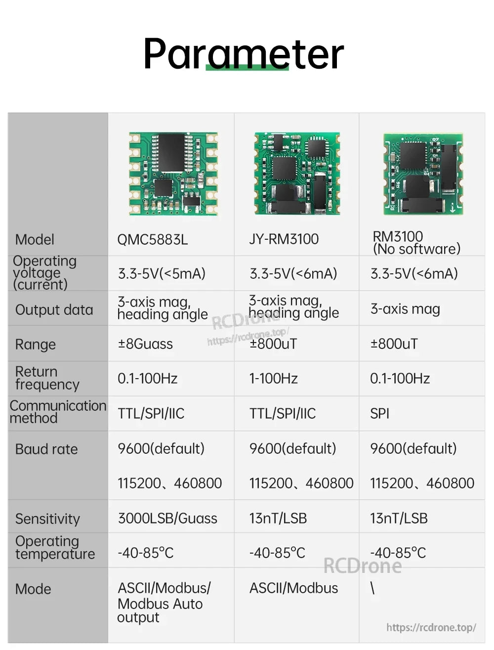
En snabb parameterjämförelse belyser mätområde, uppdateringsfrekvens och gränssnittsalternativ över vanliga kompasslösningar.
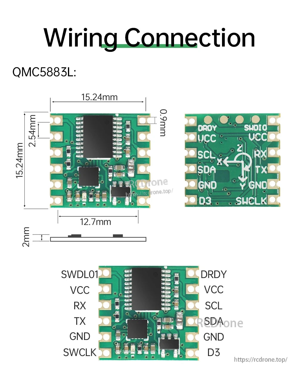
Tydlig märkning av stift hjälper till att kartlägga ström, UART och I2C-anslutningar när modulen integreras i en kontroller eller utvecklingskort.
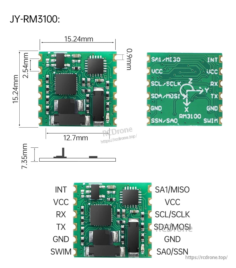
Stansade "stämphål" kanter och multi-gränssnitt stiftkonfiguration förenklar lödning och integration för TTL, SPI eller I2C byggen.
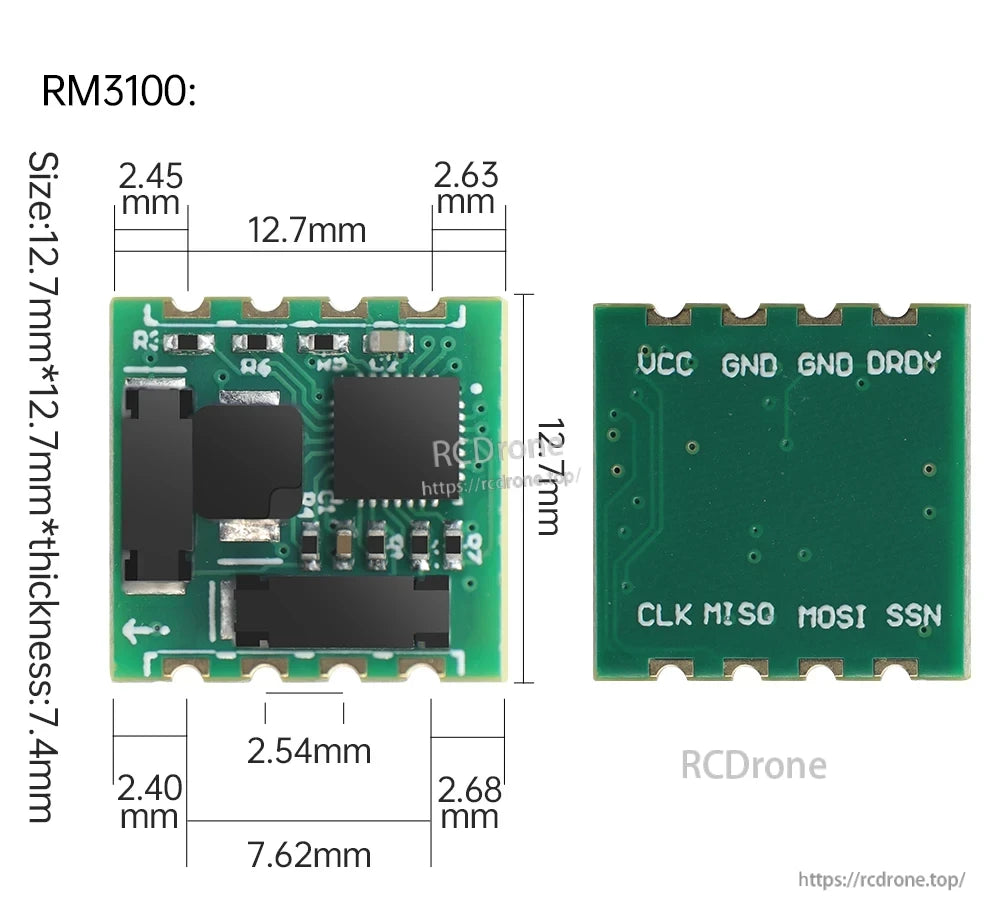
Mechaniska dimensioner och märkta pads stödjer snabb PCB-layout för RM3100-baserade designer.
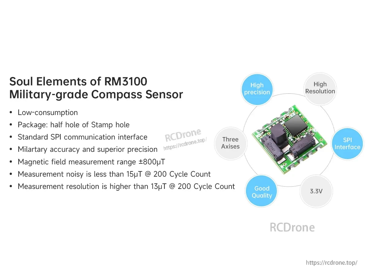
Fluxgate-sensorering och ett standard SPI-gränssnitt gör RM3100-moduler till en stark kandidat för robotik, UAV och navigationsprojekt.
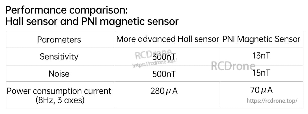
En sid-vid-sid jämförelse framhäver de lägre brus- och lägre strömförbrukningsfördelarna med PNI-magnetiska sensoransatsen.
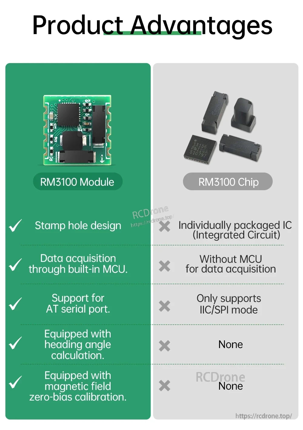
Att välja hela modulen lägger till inbyggd datainsamling och seriella funktioner, inklusive beräkning av kursvinkel och stöd för nollbiaskalibrering.
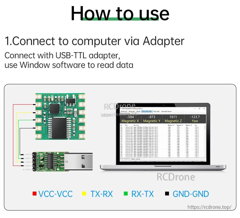
Grundläggande USB‑TTL-koppling (VCC, GND och korsade TX/RX) möjliggör snabb PC-testning innan integration med en flygkontroller eller MCU.
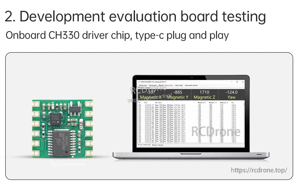
En valfri utvärderingsuppsättning med inbyggd USB-drivrutin stöder plug-and-play-testning för snabb prototypframställning.
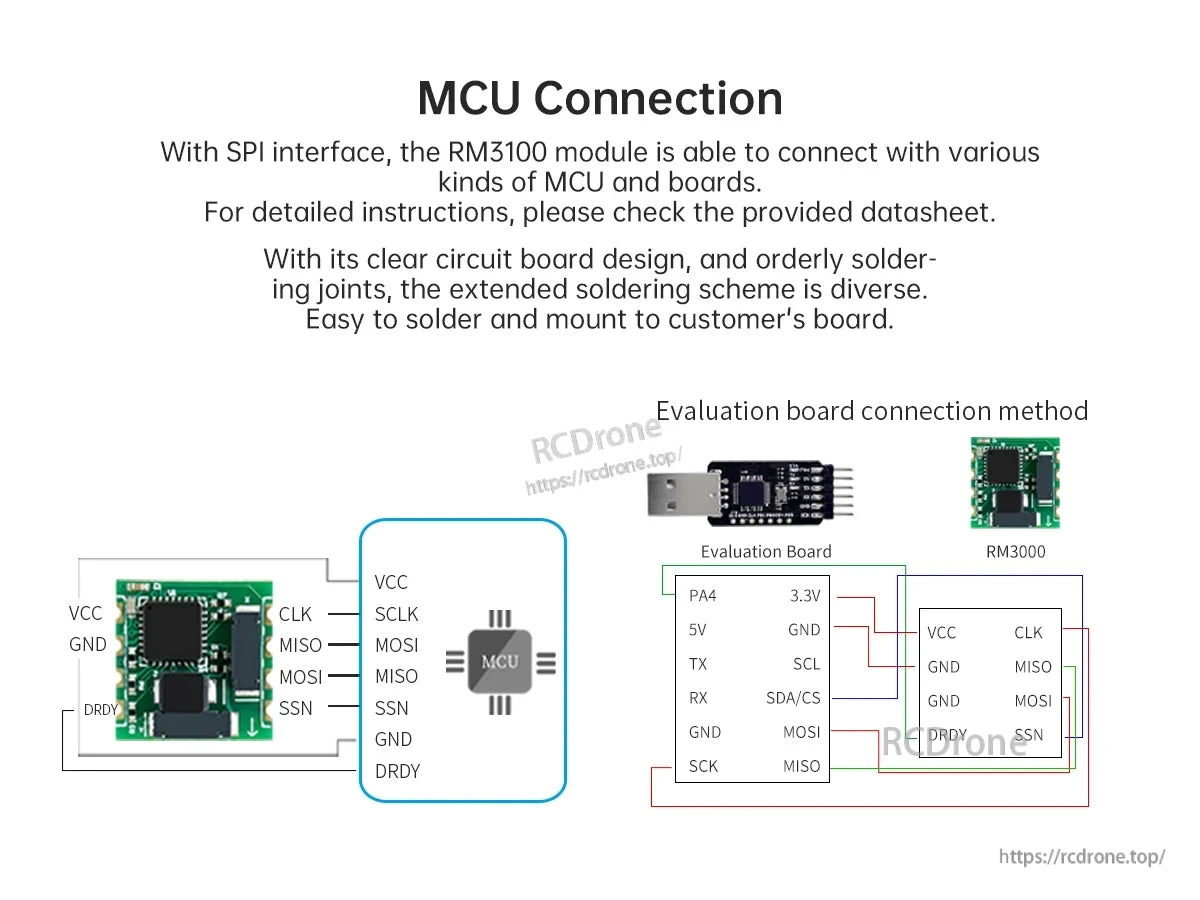
RM3100-kompassmodulen använder en enkel pin-header-layout med märkta ström- och SPI-signalkontakter för att förenkla MCU-kopplingen.
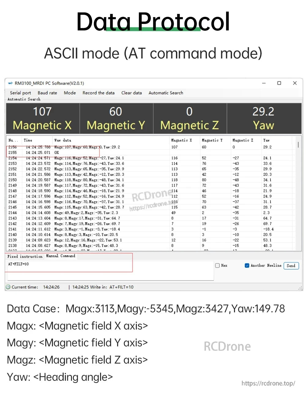
JY-RM3100-kompassmodulen ger ut Magnetisk X, Magnetisk Y, Magnetisk Z och yaw-data i ASCII (AT-kommandon) läge för seriell analys.
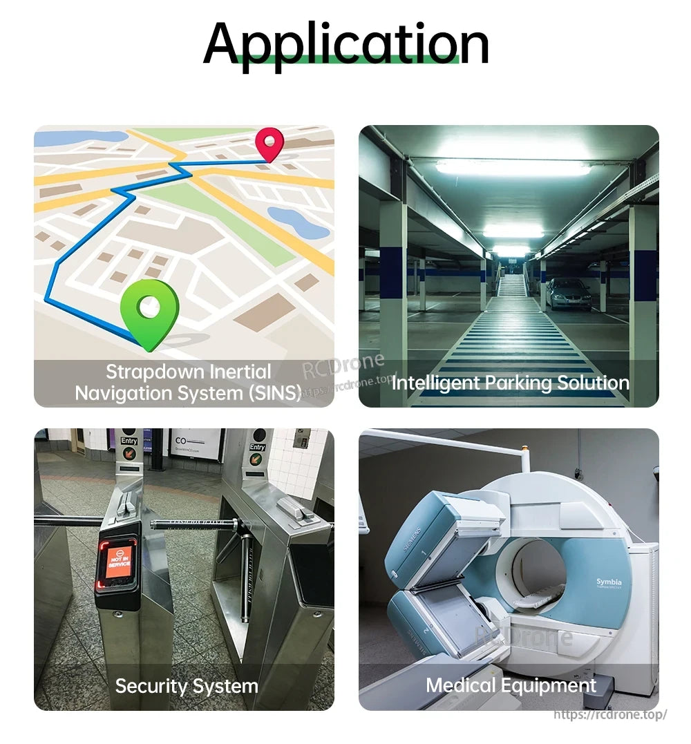
En 3-axlig elektronisk kompassmodul kan integreras i navigationssystem, parkeringslösningar, säkerhetsåtkomstkontroll och medicinsk utrustning.
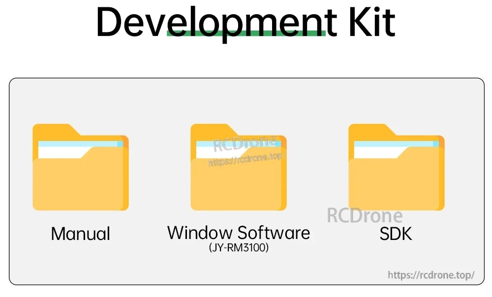
Utvecklingssatsen inkluderar en manual, Windows-programvara (JY-RM3100) och ett SDK för att hjälpa till med installation och integration.
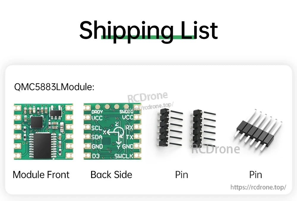
Paketet inkluderar en QMC5883L-modul med fram/bak-layout och flera stiftkontakter för lödning till ditt projekt.
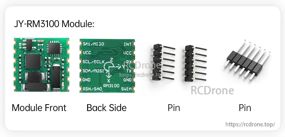
JY-RM3100-kompassmodulen inkluderar separata stiftkontakter och tydligt märkta pads för att koppla ström, datalinjer och avbrott.