CHIHAI CHS-GM1024-10BY Mini Geared Stepper Motor, 5V D-Shaft
CHIHAI CHS-GM1024-10BY Mini Geared Stepper Motor, 5V D-Shaft
CHIHAI MOTOR
Haikuweza kupakia upatikanaji wa kuchukua


The CHIHAI MOTOR CHS-GM 1024-10BY is a miniature geared stepper motor with a same-side motor and output shaft layout. Choose six actual reduction ratios and a motor-only, driver-board or enclosed-driver package. The compact metal gearbox and 3 mm D-shaft suit small positioning mechanisms.
- Two-phase, four-wire permanent-magnet stepper with metal reduction gears.
- 18-degree motor step angle reduced through the selected gearbox.
- Short D-shaft for compact couplings and mechanisms.
- Optional push-button driver packages shown in the package selector.
| Model | CHIHAI MOTOR CHS-GM 1024-10BY |
| Motor type | Two-phase, four-wire permanent-magnet geared stepper; same-side motor and output shaft arrangement |
| Winding reference | DC 5 V, 128 mA per phase; use a suitable bipolar stepper driver |
| Motor step angle | 18 degrees before gearbox |
| Phase resistance / inductance | 39 ohm ±7% per phase / 14.3 mH per phase |
| Reduction ratios | 50: 1, 100: 1, 150: 1, 200: 1, 350: 1, 500: 1 |
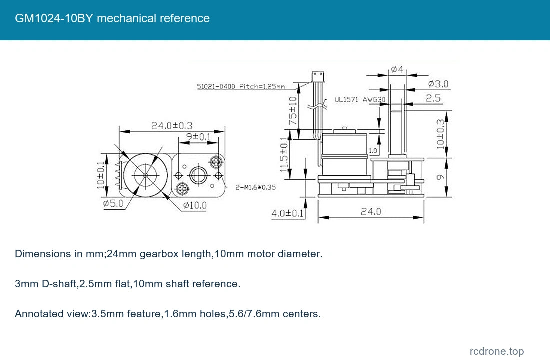
| Shaft | 3 mm D-shaft, 2.5 mm flat reference, 10 mm shaft reference |
| Dimensions | Approximately 24 mm gearbox length; 10 mm motor diameter; see drawing for mounting geometry |
| Mass | Approximately 10.5 g motor reference, excluding driver and packaging |
| Lead / connector | Four-wire lead, 1.25 mm-pitch four-pin connector reference |
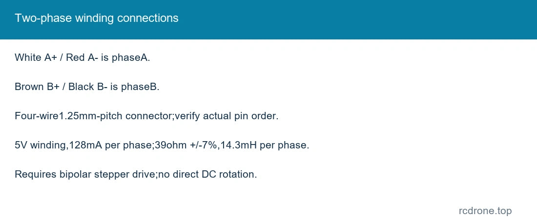
| Winding colors | White A+, Red A−, Brown B+, Black B−; verify actual pin order before connection |
| Holding torque | Ratio-dependent reference; 3.0 kgf·cm is maximum permitted holding/load limit for higher ratios, not continuous running torque |
| Frequency headings | Maximum starting frequency > 1200 pps and maximum response frequency > 900 pps as labeled test references; driver/load dependent |
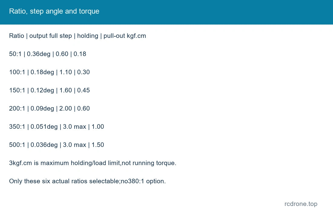
| Ratio | output full-step degrees | holding kgf·cm | pull-out kgf·cm | 50: 1 | 0.36 | 0.60 | 0.18 |
| Ratio | output full-step degrees | holding kgf·cm | pull-out kgf·cm | 100: 1 | 0.18 | 1.10 | 0.30 |
| Ratio | output full-step degrees | holding kgf·cm | pull-out kgf·cm | 150: 1 | 0.12 | 1.60 | 0.45 |
| Ratio | output full-step degrees | holding kgf·cm | pull-out kgf·cm | 200: 1 | 0.09 | 2.00 | 0.60 |
| Ratio | output full-step degrees | holding kgf·cm | pull-out kgf·cm | 350: 1 | 0.051 | 3.0 max | 1.00 |
| Ratio | output full-step degrees | holding kgf·cm | pull-out kgf·cm | 500: 1 | 0.036 | 3.0 max | 1.50 |
Holding and pull-out torque are different operating references. The 3.0 kgf·cm figure is an upper holding/load limit, not a continuous rotating torque guarantee. Speed and torque depend on drive voltage, current, frequency, load and acceleration. Only the six selectable ratios are supplied.
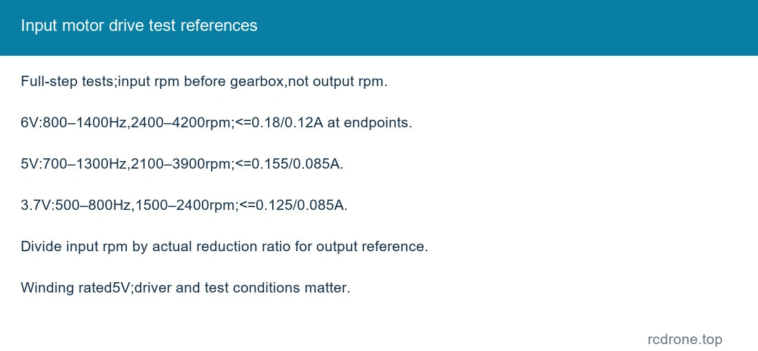
The following are input-motor full-step test references before reduction, not gearbox output speeds. Divide motor rpm by the selected ratio for approximate no-load output rpm; actual usable speed requires testing with the chosen driver and load.
| 6.0 V test | 800–1400 Hz; 2400–4200 input rpm; current ≤0.18 A at 800Hz/≤0.12 A at 1400Hz; 0Hz hold≤0.30A |
| 5.0 V test | 700–1300 Hz; 2100–3900 input rpm; current ≤0.155 A at 700Hz/≤0.085 A at 1300Hz; 0Hz hold≤0.25A |
| 3.7 V test | 500–800 Hz; 1500–2400 input rpm; current ≤0.125 A at 500Hz/≤0.085 A at 800Hz; 0Hz hold≤0.19A |
These test voltages do not replace the 5 V winding rating. The phase-current specification is 128mA/phase; test supply-current readings are a separate measurement.
Winding pairs: White A+ with Red A−; Brown B+ with Black B−. Use a bipolar stepper driver and confirm actual connector pin numbering. A stepper needs sequenced excitation; do not connect it directly to a DC supply for rotation.
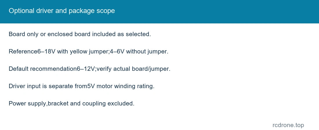
The optional board supply reference is 6–18V with the yellow jumper installed, or 4–6V without it; the default recommendation is 6–12V. Confirm the supplied board and jumper before powering. Driver supply voltage is not the motor winding voltage. The enclosed package adds the pictured housing; no power supply is included.
Approximately 24mm gearbox length, 10mm motor diameter, 3mm D-shaft and 10mm shaft reference. The annotated mounting view shows 3.5mm feature diameter, 1.6mm mounting holes, and 5.6/7.6mm center references. Consult the dimensioned drawing for fit. Support external loads; avoid shaft side loads, gear overload, resonance and long high-current standstill.
Motor Only: one selected-ratio motor with attached lead. Motor + Driver Board: one motor and pictured board. Motor + Enclosed Driver: one motor and driver with pictured enclosure. Power supply, coupling and mounting bracket excluded.
Small camera mechanisms, pan/tilt prototypes, miniature instruments, robotic actuators and compact positioning experiments.
No.This CHS version uses the short 3mm D-shaft and same-side arrangement.
It requires a bipolar stepper driver to sequence the two windings; use the selected driver within its actual input limits.
Visual Details