


TSL1401 128-Piksel Lineer CCD Kamera Modülü 3.3-5V AO Çıkışlı MCU Akıllı Araba Hat Takip
TSL1401 128-Piksel Lineer CCD Kamera Modülü 3.3-5V AO Çıkışlı MCU Akıllı Araba Hat Takip
Yahboom
Teslim alım stok durumu yüklenemedi
Genel Bakış
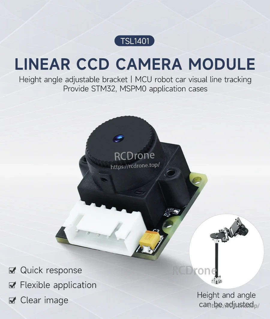
TSL1401 Lineer CCD Kamera Modülü, taranan bir sahneyi elektrik sinyaline dönüştürmek için 128 piksellik lineer CCD (128 × 1) kullanır. Toplanan gri değer verileri, AO pininde analog voltaj olarak çıkış verir ve robot araba görsel hat izleme, yol tanıma, takip, engel kaçınma ve diğer görüntü işleme görevleri için bir mikrodenetleyici A/D dönüştürücüsü tarafından örneklenebilir. Modül, hızlı yanıt için tasarlanmıştır ve ortam ışığından daha az etkilenir, iç ve dış mekan yüksek hızlı takip kullanımını destekler.
Ana Özellikler
- 128 piksellik lineer CCD (128 × 1), lineer tarama alımı
- Çalışma voltajı: DC 3.3V–5V
- Algılama mesafesi: 5–40 cm içinde (lens nedeniyle uzun mesafe ileri görüş testleri için uygun değildir)
- Lens: 56 derece distorsiyonsuz lens
- Hızlı yanıt; net görüntü; esnek uygulama
- Üzerinde 5Pin XH2.54 tersine bağlantı noktası; pin çıkışı: GND, VCC, AO, CLK, SI
- Yükseklik/ açı ayarlanabilir braket mevcut (isteğe bağlı)
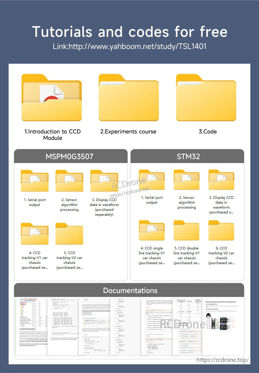
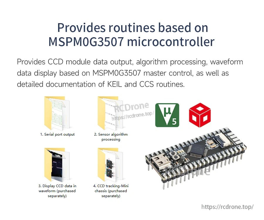
- STM32 sürücü kodu ve eğitimleri sağlanmıştır (STM32/MSPM0 uygulama durumları ile de gösterilmiştir)
Bağlantı soruları veya ön satış uyumluluk kontrolleri için iletişime geçin [email protected] or ziyaret edin https://rcdrone.top/.
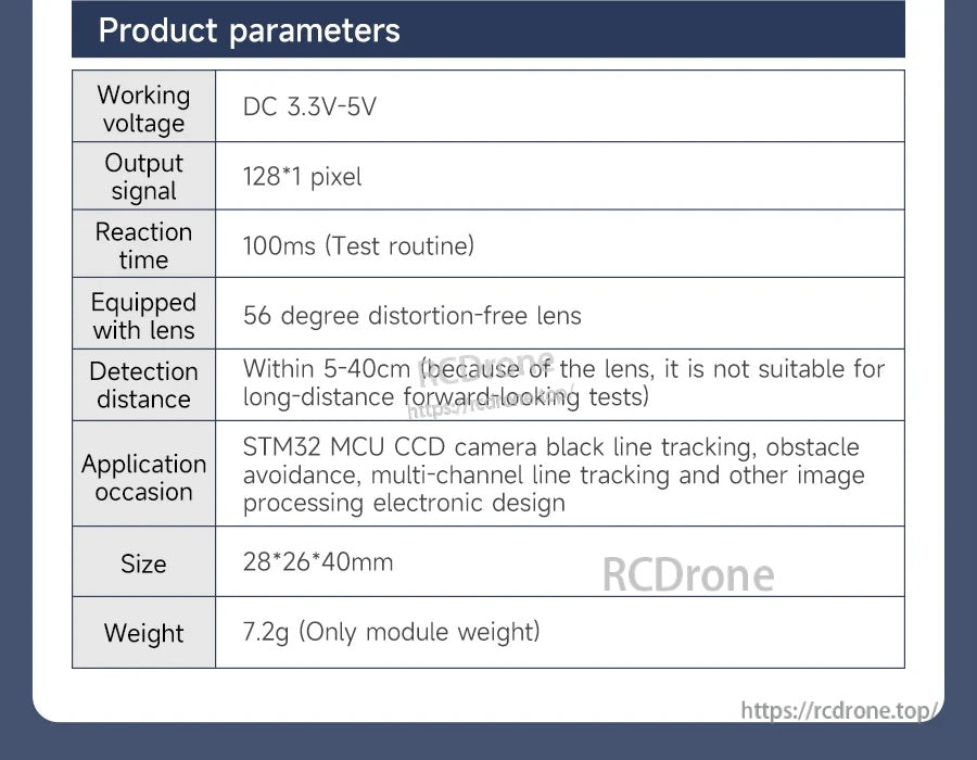
Teknik Özellikler
| CCD çıkış sinyali | 128*1 piksel |
| Çalışma voltajı | DC 3.3V-5V |
| Reaksiyon süresi | 100ms (Test rutini) |
| Lens | 56 derece distorsiyonsuz lens |
| Algılama mesafesi | 5-40cm içinde (lens nedeniyle, uzun mesafeli ileriye dönük testler için uygun değildir) |
| Uygulama durumu | STM32 MCU CCD kamera siyah hat takibi, engelden kaçınma, çok kanallı hat takibi ve diğer görüntü işleme elektronik tasarımı |
| Boyut | 28*26*40mm |
| Ağırlık | 7.2g (Sadece modül ağırlığı) |
Mekanik çizim boyutları (birim: mm)
| Modül montaj delikleri | 4-φ2 |
| Modül ön genişliği | 25 |
| Modül iç genişliği | 21 |
| Modül ön yüksekliği | 24 |
| Modül referans yükseklikleri | 13; 9.00 |
| Modül yan referans uzunlukları | 5.71; 7.33; 17.46; 19.02 |
| Lens/optik konut çapları | φ14; φ15 |
Yükseklik/angle ayarlanabilir braket boyutları (birim: mm)
| Yükseklik ayar aralığı (modül yüksekliği) | 1.2~9.5cm |
| Üst plaka genişliği | 30 |
| Üst plaka köşe yarıçapı | R1.50 |
| Dikey boyutlar için braket | 19; 35.50 |
| Genel yükseklik (çizim) | 148.15 |
| Yan profil genişliği (çizim) | 36.20 |
| Taban genişliği (çizim) | 54 |
| Alt özellik çapı | φ22 |
| Alt montaj delikleri | 4-φ3 |
| Ek delik | φ3 |
| Gösterilen referans boyutları | 16 (taban çiziminde tekrar edilmiştir) |
| Eğim açısı | Esnek bir şekilde ayarlanabilir |
Pinout
| GND | Güç kaynağı pini, toprak. |
| VCC | Güç kaynağı pini, DC 3.3V-5V bağlayın. |
| AO | Gri değer çıkış pini, analog çıkış. |
| CLK | Saat pini, pozlama süresini belirler ve piksel gri değerinin çıktısını kontrol eder. |
| SI | Piksel gri değerinin edinimini ve çıktısını kontrol eder. |
Uygulamalar
- MCU robot araba görsel hat izleme (tek hat, çift hat ve çok kanallı hat izleme)
- Akıllı araba yol tanıma ve izleme
- Görüntü/hat özellik işleme temelinde engel kaçınma
- STM32 uygulama geliştirme ve öğrenme projeleri (uygulama örnekleri MSPM0 için de gösterilmektedir)
Detaylar
TSL1401 modülü, hızlı hat izleme için 128 pikselden oluşan tek bir hattı analog gri değer çıktısına dönüştürür.
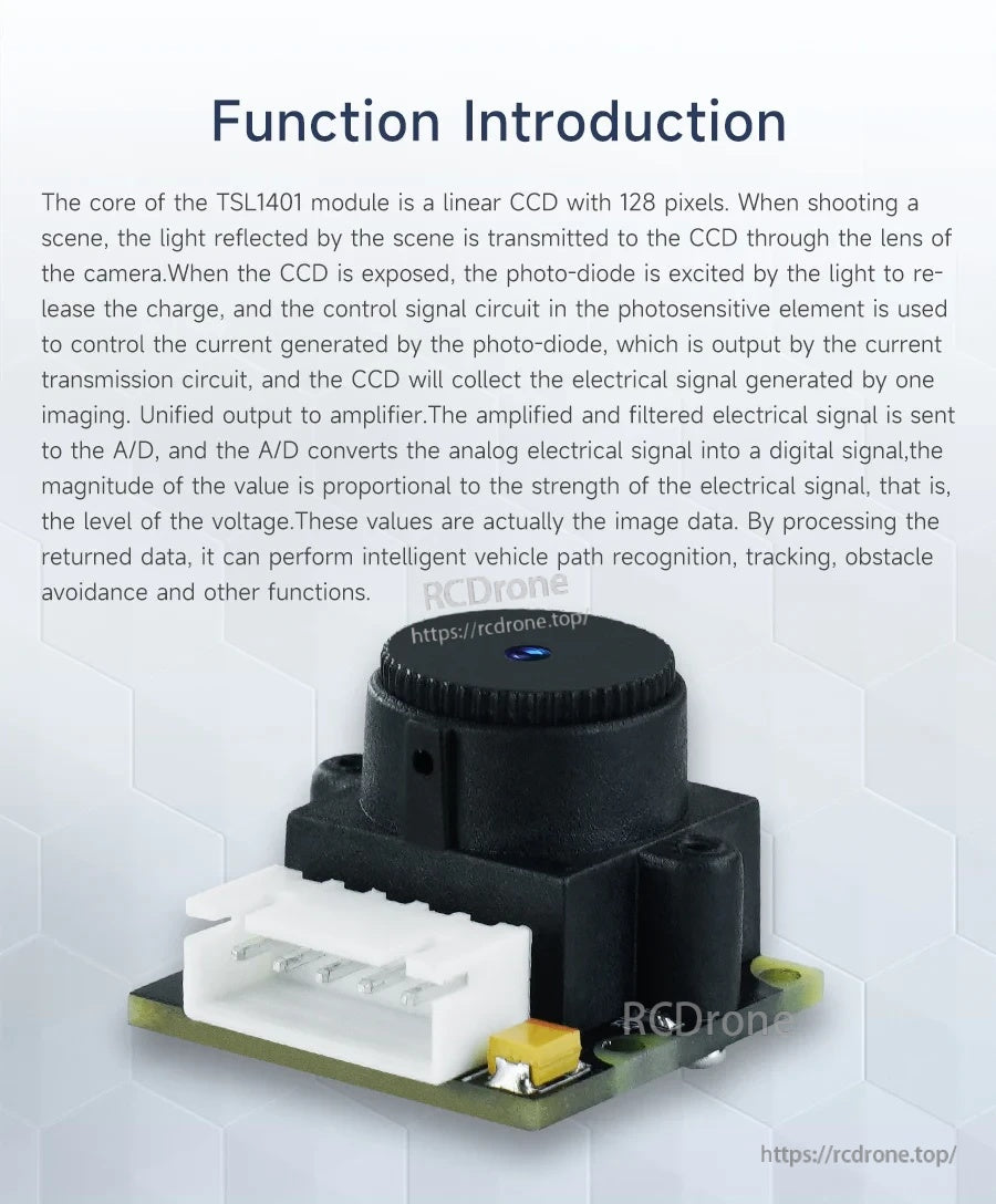
MCU projeleri için tasarlanmış olan analog AO çıkışı, izleme ve basit görsel görevler için bir ADC tarafından örneklenebilir.
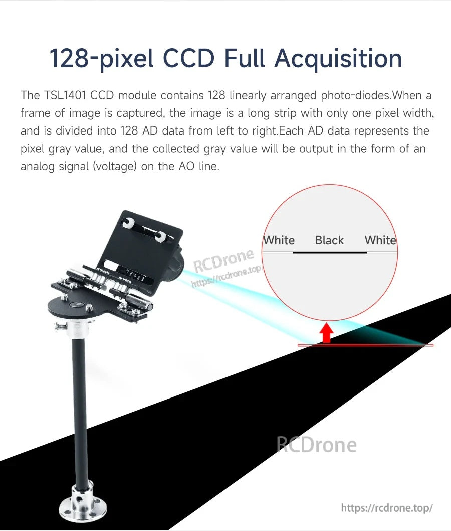
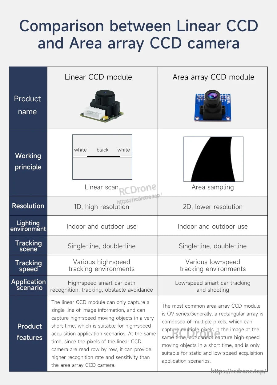
1D bir hat taraması, tam çerçeve kameralarla karşılaştırıldığında işlem yükünü azaltırken, kenar ve hat kontrastını da yakalar.
Doğrusal tarama, yalnızca navigasyon için gerekli olan hat verilerini örnekleyerek daha yüksek hızda takip sağlamaya yardımcı olur.
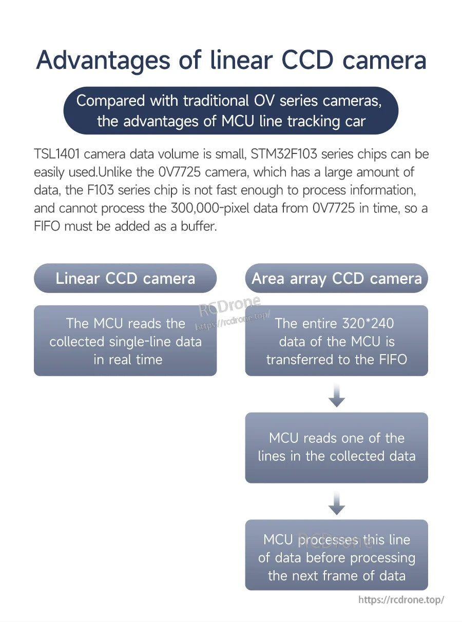
Her karede daha az veri, daha basit bir yazılım ve tipik mikrodenetleyicilerde daha hızlı yanıt anlamına gelir.
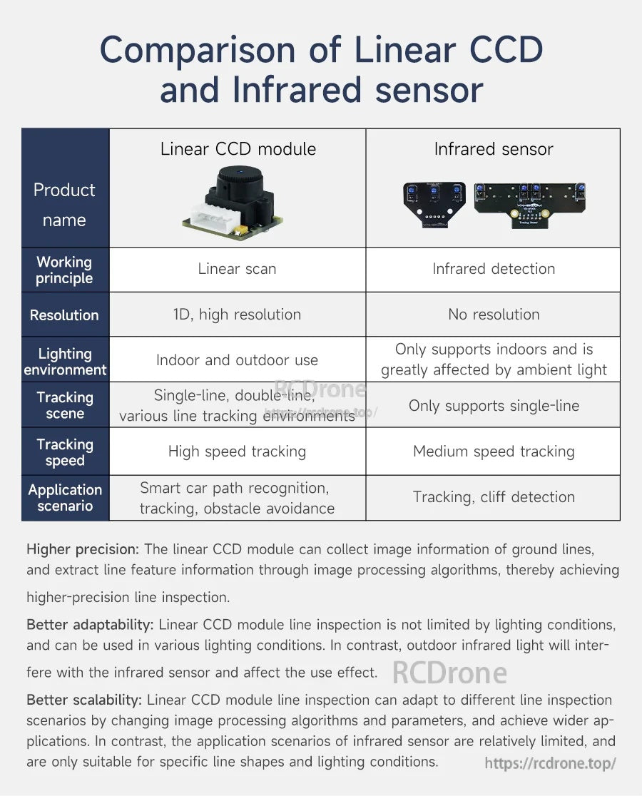
Ortam ışığının değiştiği uygulamalar için, doğrusal CCD yaklaşımı IR algılamadan daha tutarlı hat bilgisi sağlayabilir.
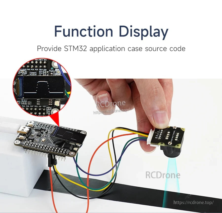
AO çıkışını almak ve SI/CLK zamanlama sinyallerini sürmek için bir STM32 kartı ile örnek bağlantı.
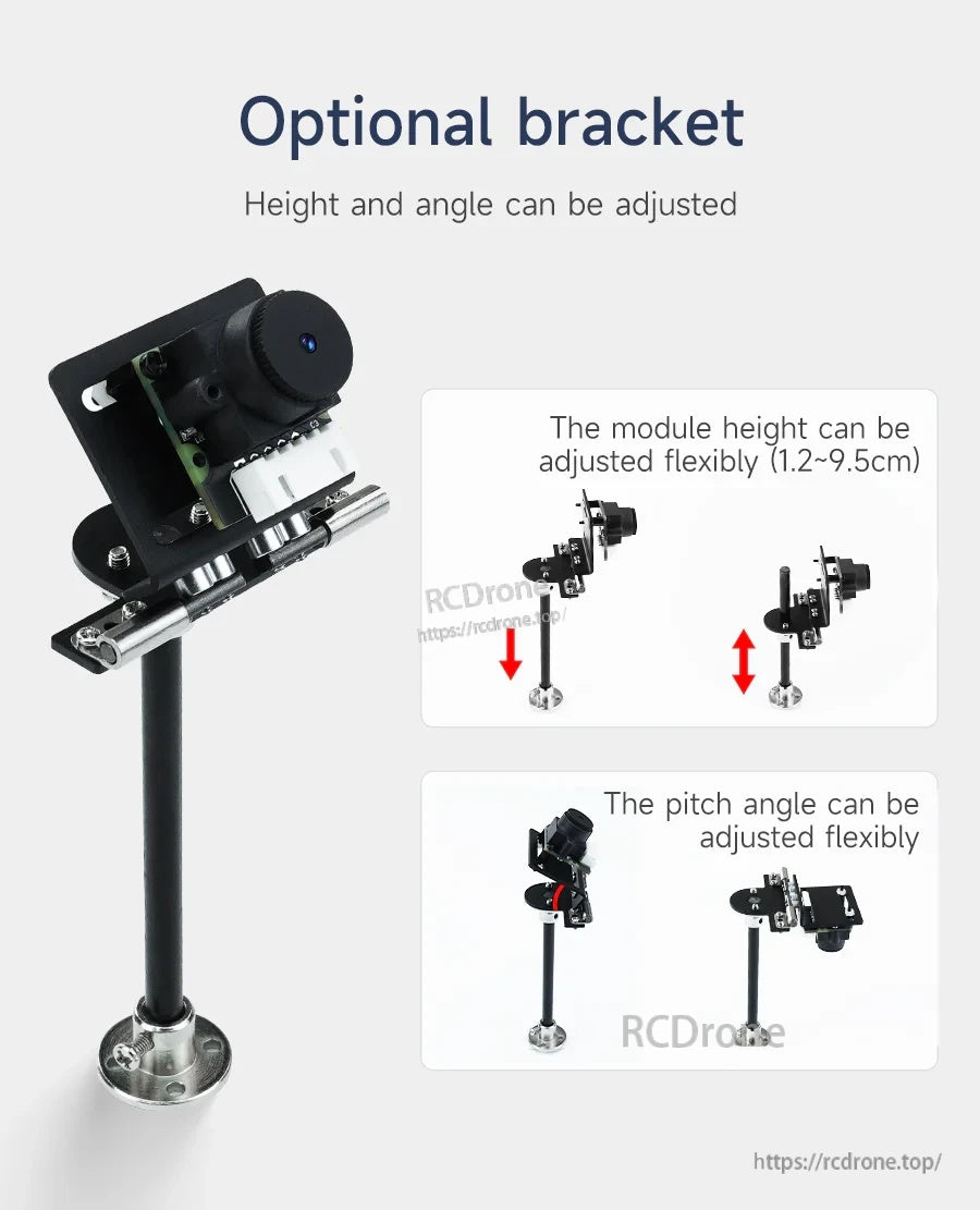
Opsiyonel bir braket, algılama mesafesi ve görüş açısını ayarlarken esnek montaj yüksekliği ve eğim açısı sağlar.
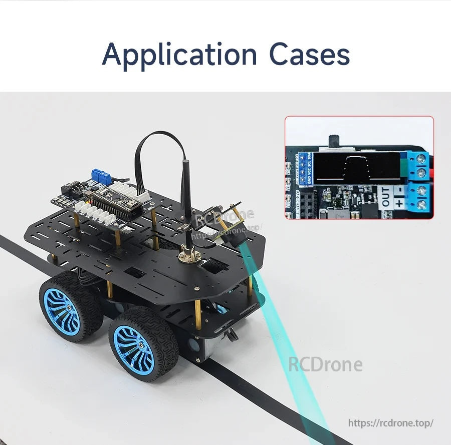
Yaygın kullanım durumu: yol tanıma ve engel kaçınma mantığı için robot araba görsel hat takibi.
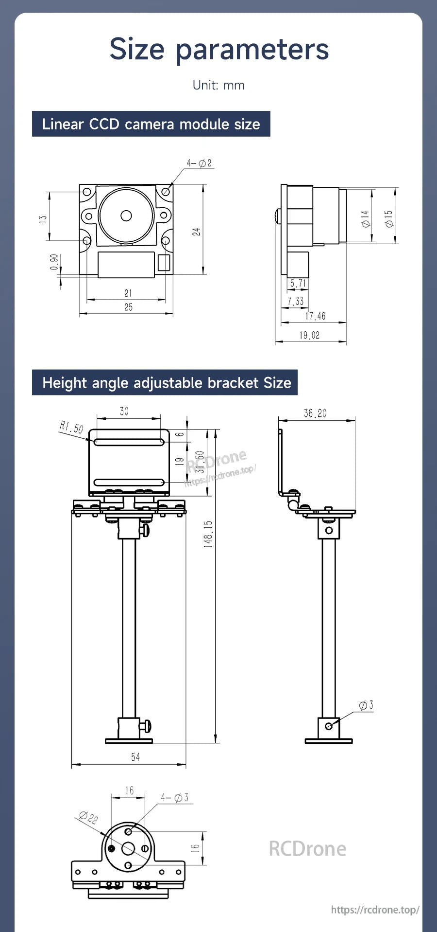
Mekanik çizimler, muhafaza ve şasi tasarımı için montaj deliği konumlarını ve genel boyutları sağlar.
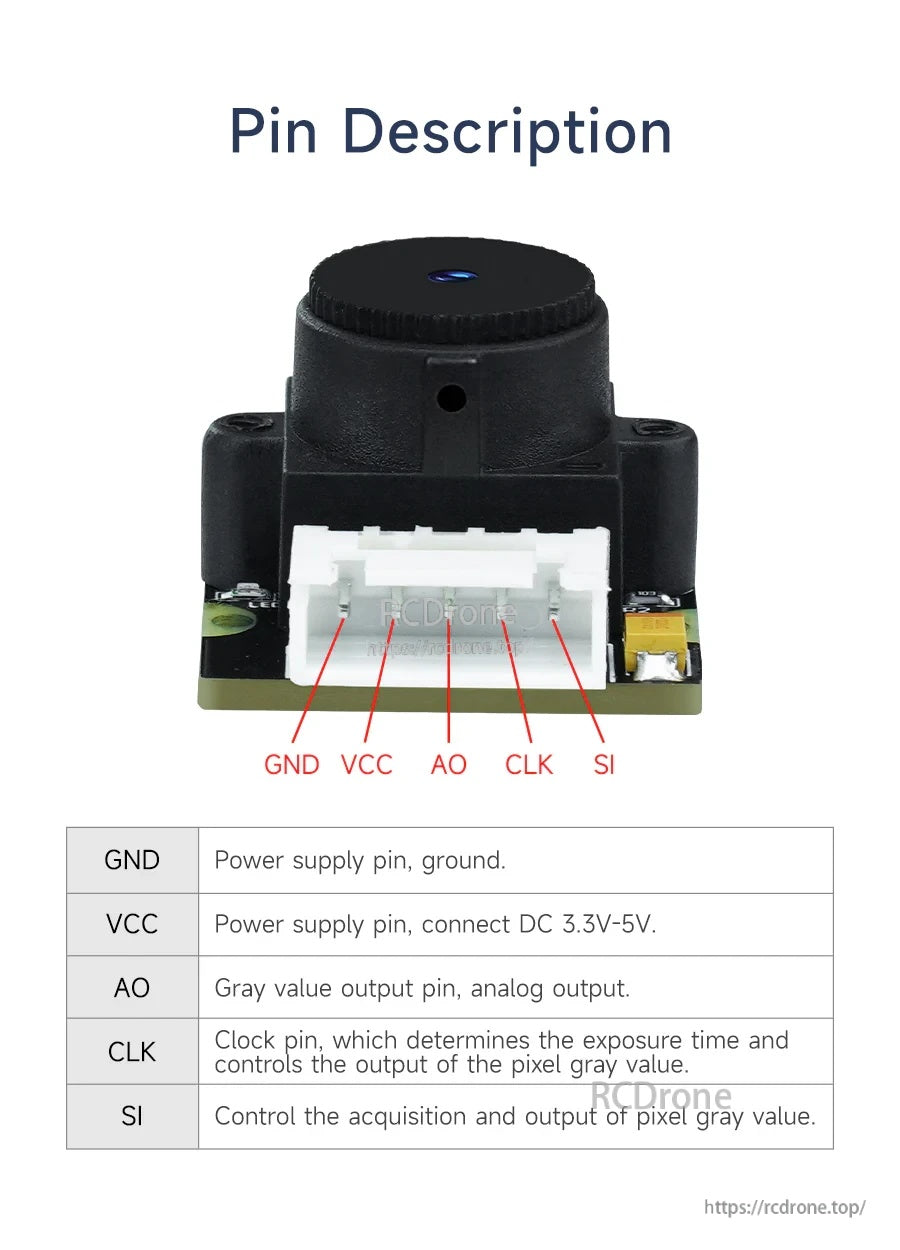
Pin çıkışı: GND ve VCC modülü besler, AO analog gri değeri çıkışı verir ve SI/CLK kontrol edinme zamanlamasını yönetir.
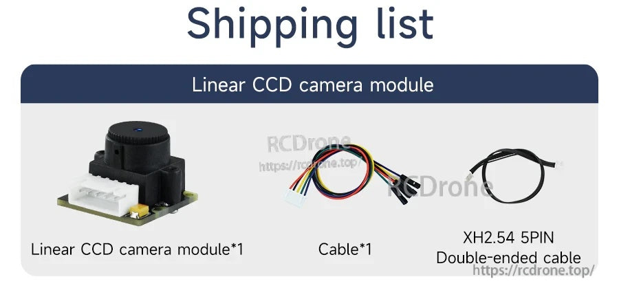
Paket, modül ve bir kontrol cihazına veya test kurulumuna hızlı bağlantı için 5-pin kablolama içerir.
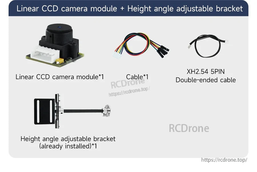
TSL1401 lineer CCD kamera modülü, yükseklik/ açı ayarlanabilir braket ile birlikte gelir ve basit kablolama için bir tel demeti ve XH2.54 5-pin çift uçlu kablo içerir.
Related Collections


