Overview
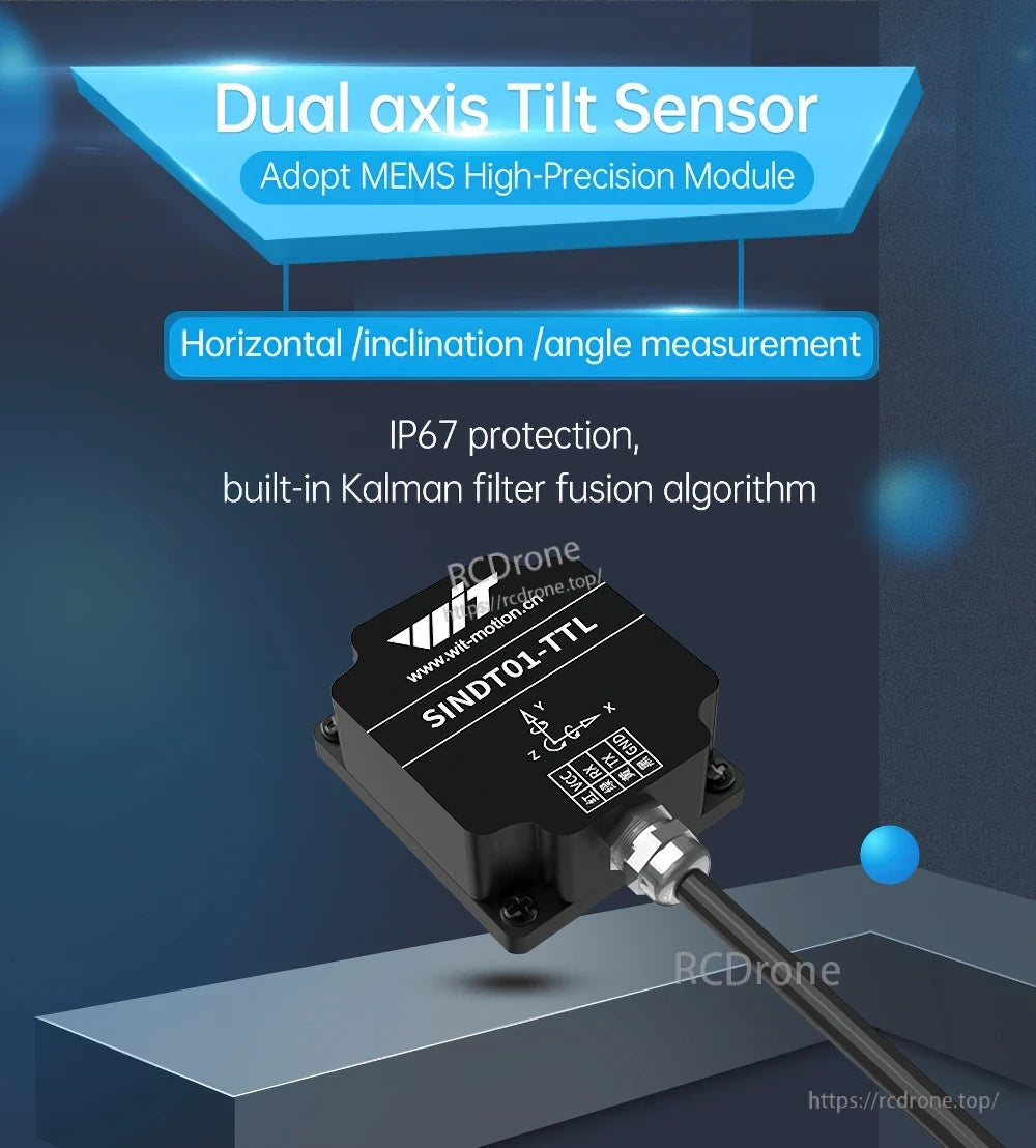
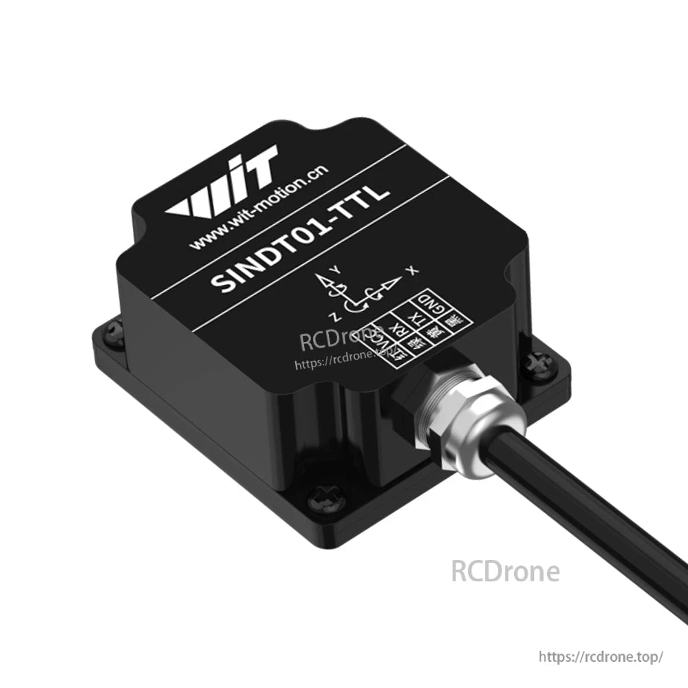
WitMotion SINDT series AHRS tilt sensor options for Modbus inclination/angle measurement: SINDT01 (single-axis) and SINDT02 (dual-axis). The series adopts a MEMS high-precision module for horizontal/inclination/angle measurement, with IP67 protection and a built-in Kalman filter fusion algorithm. A free PC software tool is provided for Modbus communication and motion-state visualization.
Key Features
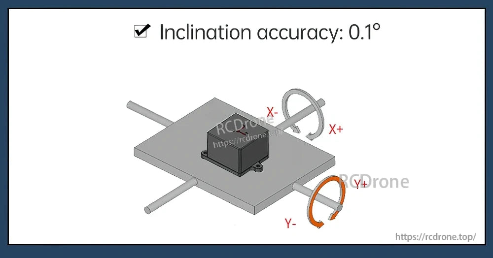
- Inclination accuracy: 0.1°
- IP67 protection
- Built-in Kalman filter fusion algorithm
- Interfaces optional: RS232, RS485, or TTL level
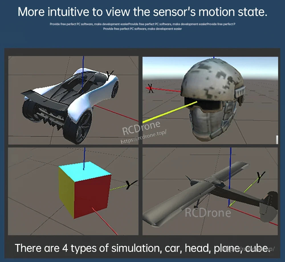
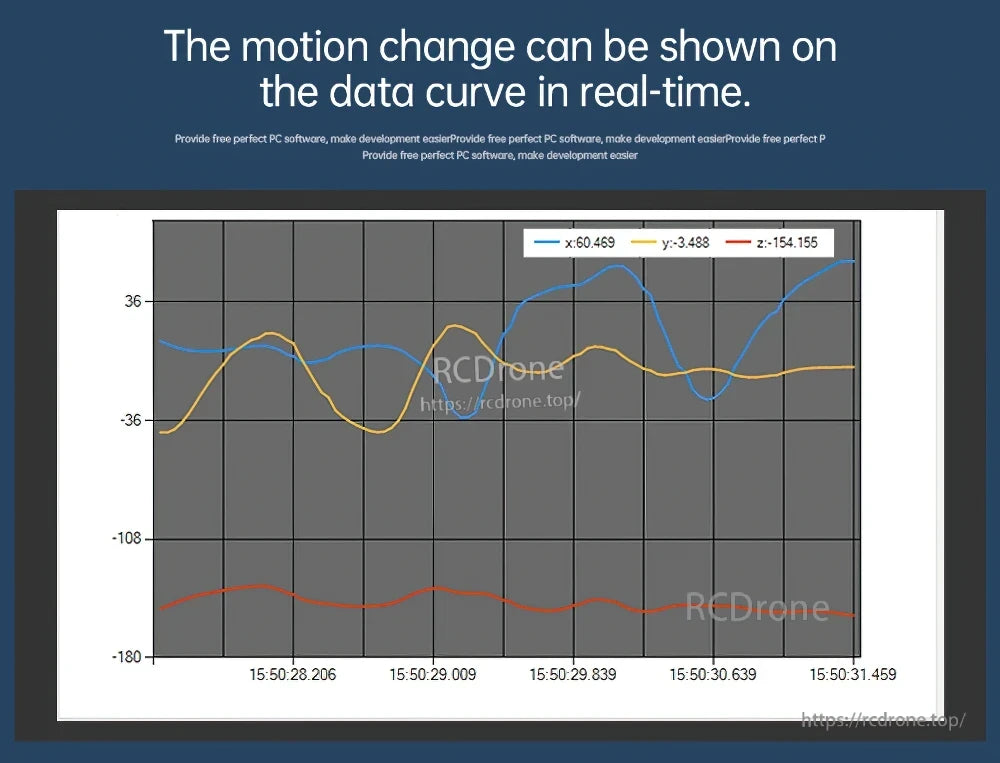
- PC software functions shown: motion-state simulation (car/head/plane/cube) and real-time data curves
- Aluminum shell; strong anti-electromagnetic interference ability; stable performance
Specifications
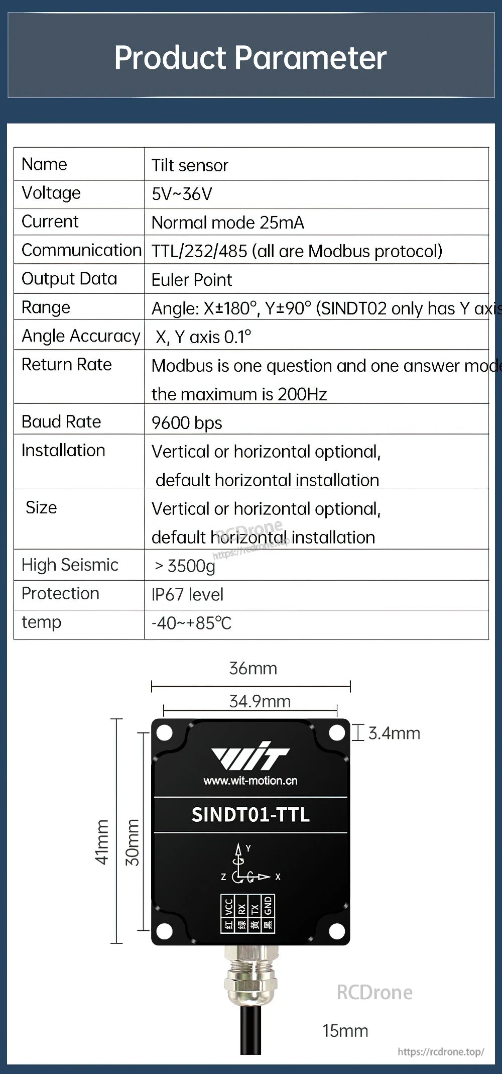
| Name | Tilt sensor |
| Voltage | 5V~36V |
| Current | Normal mode 25mA |
| Communication | TTL/232/485 (all are Modbus protocol) |
| Output Data | Euler Point |
| Range | Angle: X±180°, Y±90° (SINDT02 only has Y axis |
| Angle Accuracy | X, Y axis 0.1° |
| Return Rate | Modbus is one question and one answer mode; the maximum is 200Hz |
| Baud Rate | 9600 bps |
| Installation | Vertical or horizontal optional, default horizontal installation |
| Size | Vertical or horizontal optional, default horizontal installation |
| High Seismic | > 3500g |
| Protection | IP67 level |
| temp | -40~+85°C |
| Mechanical dimensions (as labeled) | 36mm; 34.9mm; 41mm; 30mm; 3.4mm; 15mm |
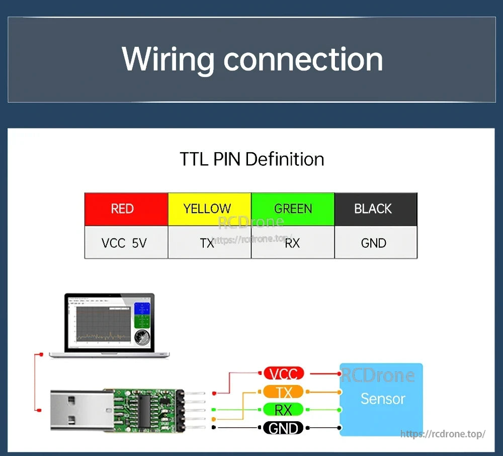
Wiring Connection (Pin Definition)
TTL
- RED: VCC 5V
- YELLOW: TX
- GREEN: RX
- BLACK: GND
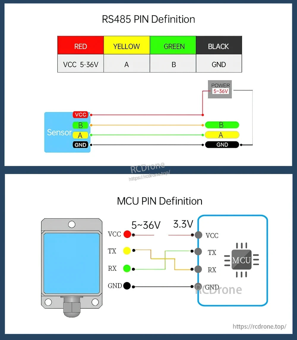
RS485
- RED: VCC 5-36V
- YELLOW: A
- GREEN: B
- BLACK: GND
MCU Connection (example shown)
- Sensor side: 5~36V power
- MCU side: 3.3V (shown)
- Signals: VCC / TX / RX / GND
Installation Precautions
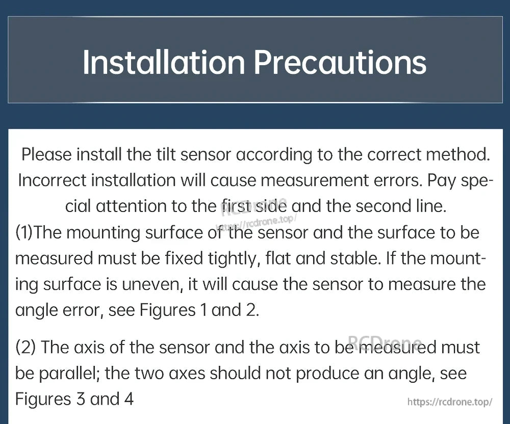
- Install the tilt sensor according to the correct method. Incorrect installation will cause measurement errors.
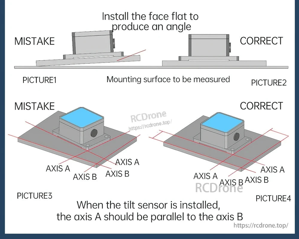
- The mounting surface of the sensor and the surface to be measured must be fixed tightly, flat and stable. If the mounting surface is uneven, it will cause angle error.
- The axis of the sensor and the axis to be measured must be parallel; the two axes should not produce an angle.
- Install the face flat to produce an angle. When the tilt sensor is installed, the axis A should be parallel to the axis B.
Applications
- Elevator equipment
- Tower crane equipment
- Turntable equipment (cloud turntable)
- Car chassis tuning (smart car)
- Medical equipment
- Solar inclination monitoring
Development Materials
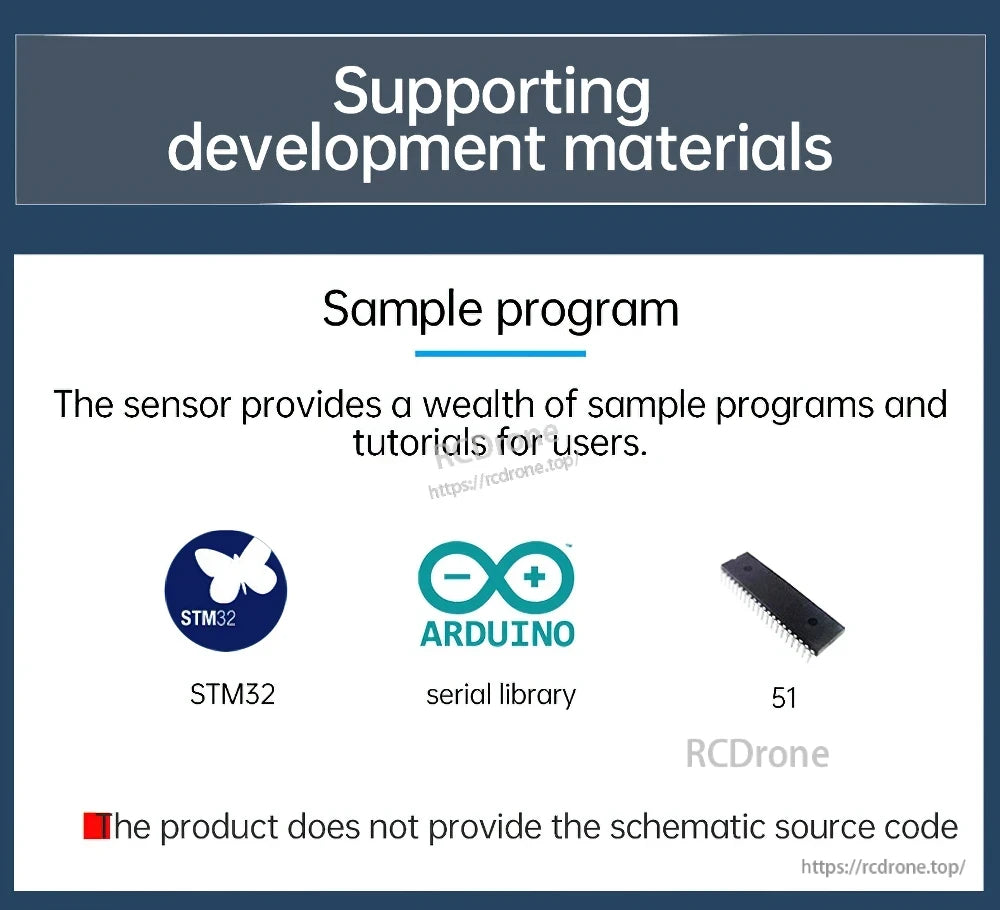
- Sample program: provides a wealth of sample programs and tutorials for users (STM32 / Arduino serial library / 51 shown)
- The product does not provide the schematic source code
Ordering Notes
Multiple SKUs may be provided as a buying guide for the related sensor series with different parameters. Verify the selected model (e.g., SINDT01 vs SINDT02) before placing the order. For pre-sales selection help or integration questions, contact support@rcdrone.top or visit https://rcdrone.top/.
Details

Built for harsh environments, the SINDT series combines MEMS tilt sensing with IP67 protection and a Kalman-filter fusion algorithm for stable angle data.

A free PC tool supports Modbus communication, live angle values, and motion-state visualization during setup and testing.

For applications that need fine leveling and pitch/roll feedback, the sensor targets 0.1° inclination accuracy.

Motion-state simulation helps validate axis orientation quickly using car, head, plane, or cube views.

Real-time curve plotting makes it easier to spot drift, vibration effects, and response changes while the machine moves.

Multiple interface options—TTL, RS232, or RS485—support Modbus integration across different controllers and wiring standards.

Common uses include elevators, tower cranes, turntables, vehicle chassis tuning, medical equipment, and solar inclination monitoring.

Key electrical specs and mechanical dimensions are summarized for faster enclosure planning and power budgeting.

Mounting quality matters: secure the sensor to a flat, stable surface and keep the measurement axis aligned to reduce angle error.

A face-flat installation and parallel axes help prevent systematic offset caused by skewed mounting surfaces.

Sample programs and tutorials are available for popular platforms such as STM32 and Arduino serial libraries.

TTL wiring uses a simple four-wire pinout—VCC, TX, RX, and GND—for quick serial integration.

RS485 connections use VCC, A, B, and GND, with an example MCU hookup included for reference.