MATEK F405-WTE - Mateksys FLIGHT CONTROLLER
MATEK F405-WTE - Mateksys FLIGHT CONTROLLER
MATEKSYS
30 orders in last 90 days
Couldn't load pickup availability
Warehouse: China/USA/Europe, can delivery to all countries;
Free Shipping: 9-15 days;
Express Shipping: 5-8 days;
Return&Refund: 30 Days.
MATEK F405-WTE - Mateksys FLIGHT CONTROLLER SPECIFICATIONS
Use: Vehicles & Remote Control Toys
Recommend Age: 12+y,14+y
Origin: Mainland China
Material: Composite Material
Brand Name: MATEKSYS
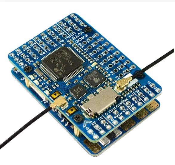
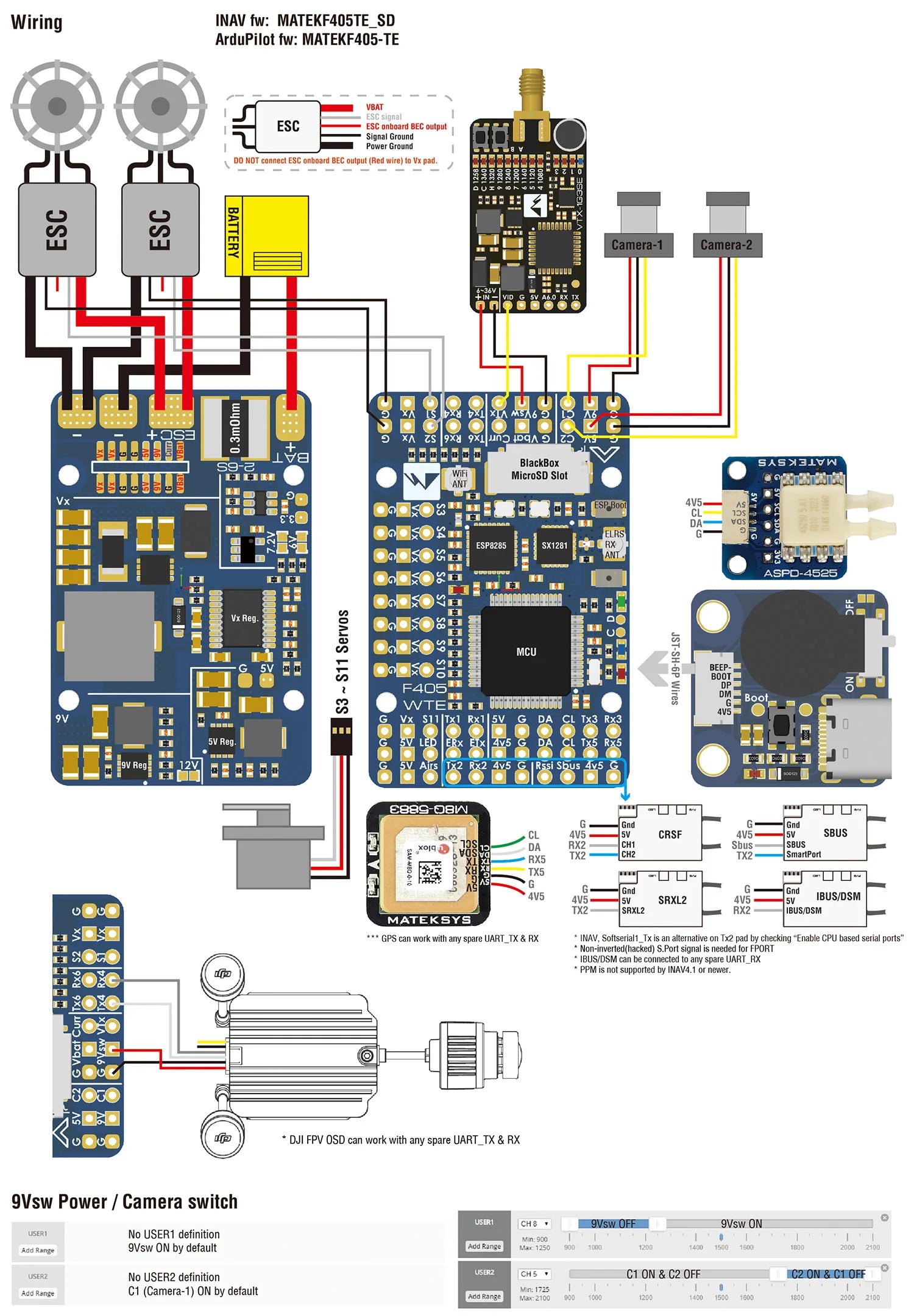
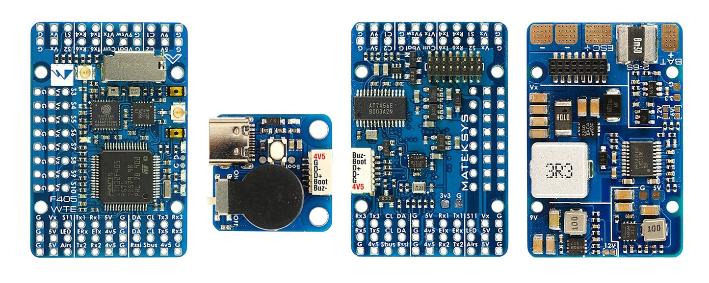
FLIGHT CONTROLLER F405-WTE
STM32F405RGT6, ICM42688P, SPL06, OSD, ESP WIFI telemetry/ELRS 2.4G receiver, 6xUARTs, 12x PWM,1xI2C
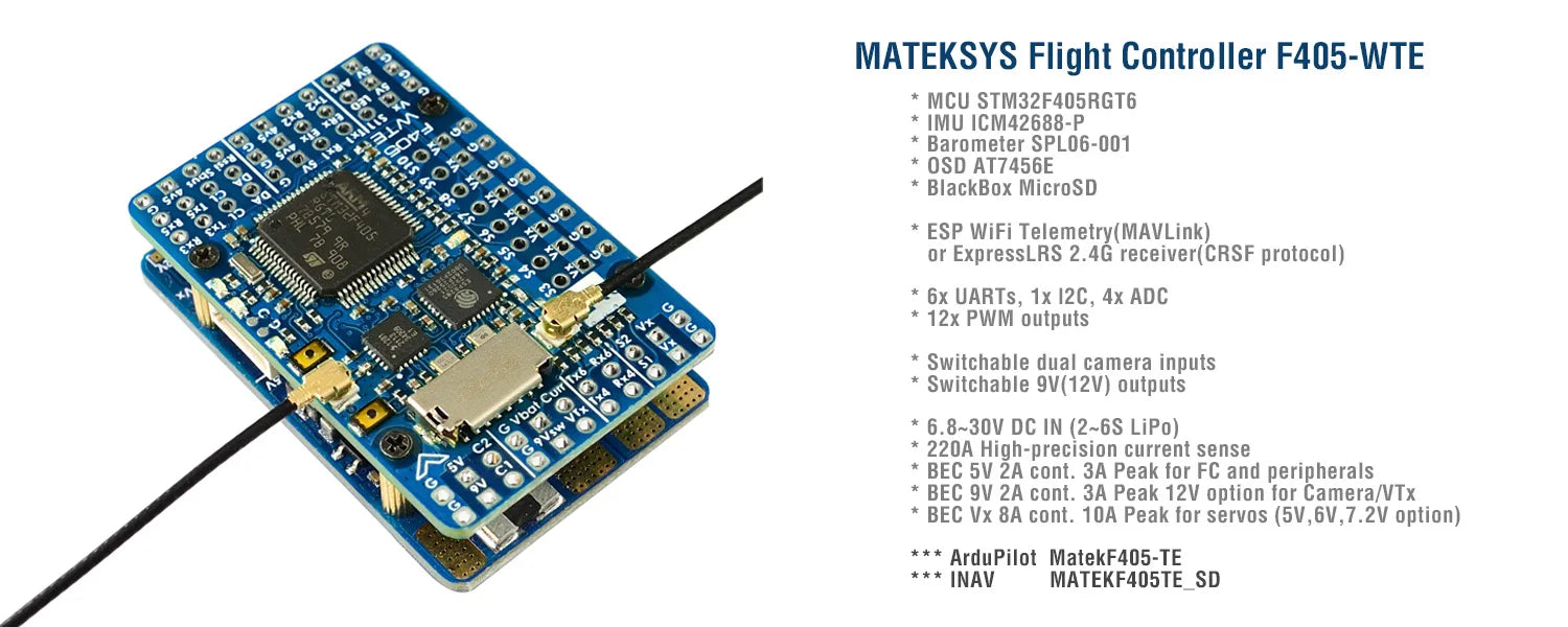
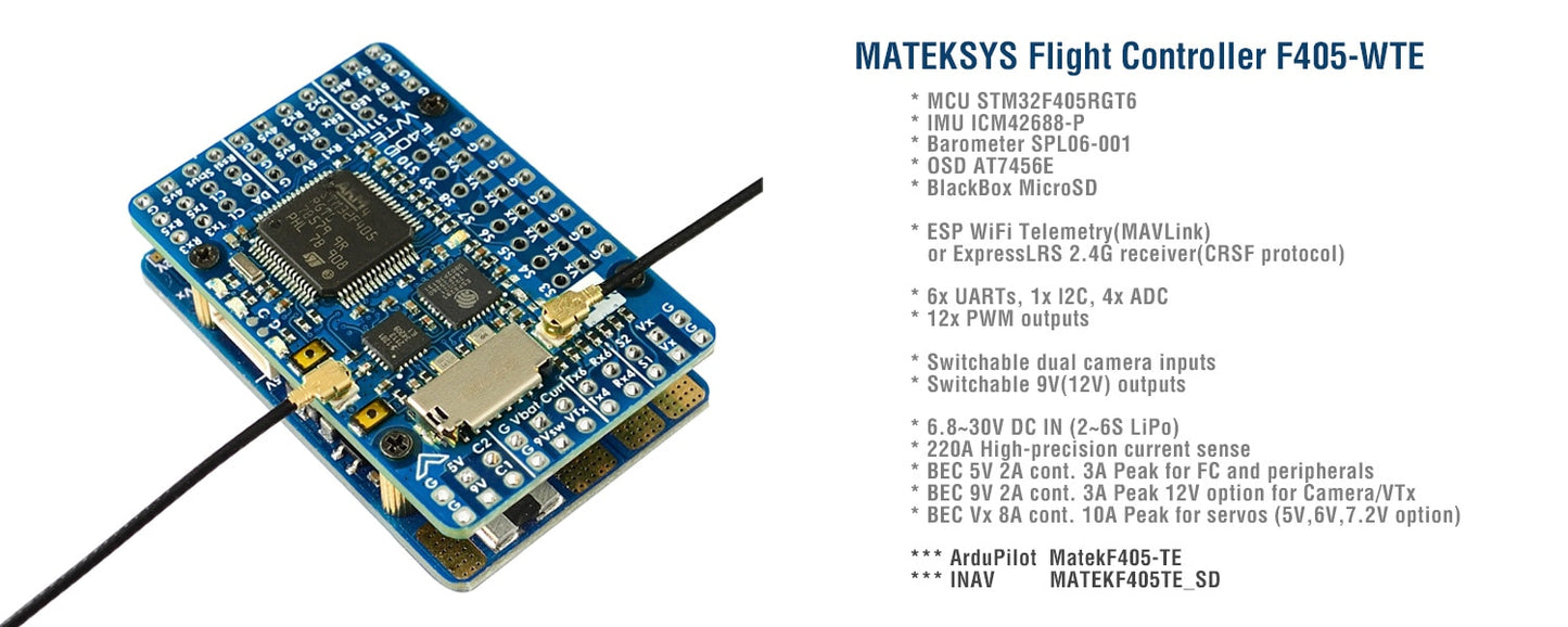
MATEKSYS Flight Controller F4O5-WTE MCU STM3ZFAOSRGT6 IMU ICM42688-P Barometer SPLO6-001 OSD AT7456E BlackBox MicroSD 2 8 2 2 2 ESP WiFi Telemetry(MAVLink) 2 or ExpressLRS 2.4G receiver(CRSF protocol) 6x UARTs , Ix I2C , 4x ADC 85 12x PWM outputs Switchable dual camera inputs 4+

FC Specifications
-
MCU: STM32F405RGT6, 168MHz , 1MB Flash
-
IMU: ICM42688-P
-
Baro: SPL06-001
-
OSD: AT7456E
-
Blackbox: MicroSD card slot
-
ESP WiFi Telemetry(MAVLink, 14dBm)
-
ExpressLRS 2.4G receiver(CRSF protocol, Telemetry 12dBm)
-
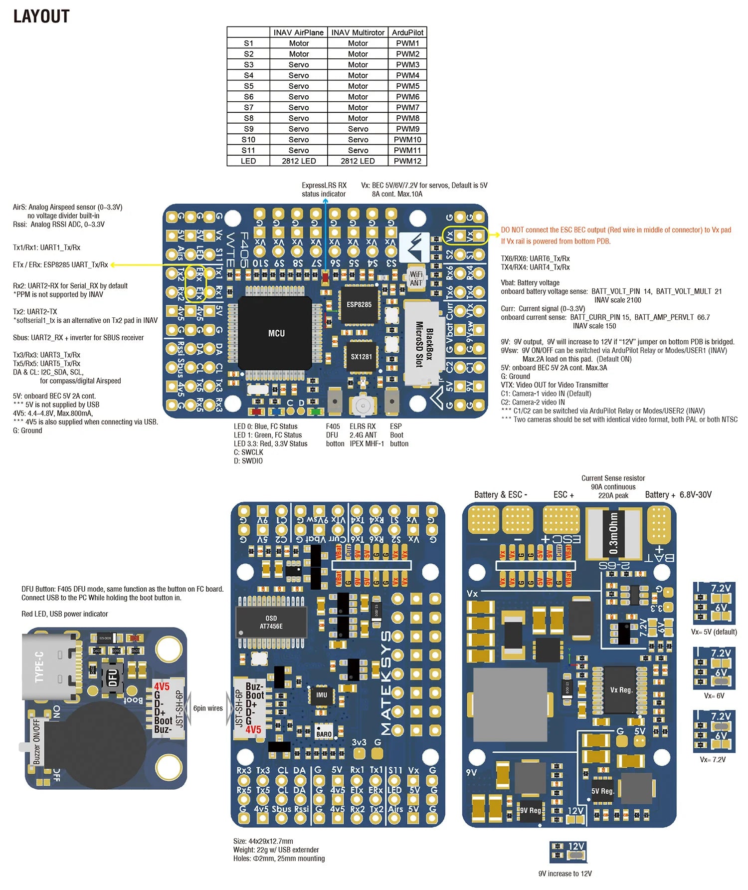
6x UARTs, 1x Softserial_Tx option(INAV)
-
12x PWM outputs
-
1x I2C
-
4x ADC (VBAT, Current, RSSI, Airspeed)
-
USB/Beep Extender with Type-C(USB2.0)
-
Dual Camera Inputs switch
-
9V(12V) for VTX power switch
FC Firmware
-
ArduPilot: MatekF405-TE
-
INAV: MATEKF405TE_SD (not available in INAV configurator 4.x)
PDB
-
Input voltage range: 6.8~30V (2~6S LiPo)
-
1x ESC power pads
-
Battery Voltage divider 1K:20K (Scale 2100 in INAV, BATT_VOLT_MULT 21.0 in ArduPilot)
-
Current Senor: 220A, 3.3V ADC (Scale 150 in INAV, 66.7 A/V in ArduPilot)
-
Sense resistor: 90A continuous, 220A peak
BEC 5V output
-
Designed for Flight controller, Receiver, OSD, Camera, Buzzer, 2812 LED_Strip, Buzzer, GPS module, AirSpeed
-
Continuous current: 2 Amps, Max.3A
BEC 9V /12V output
-
Designed for Video Transmitter, Camera, Gimbal ect.
-
Continuous current: 2 Amps, Max.3A
-
12V option with Jumper pad
-
for stable 9V/12V output, input voltage should > output voltage +1V
BEC Vx output
-
Designed for Servos
-
Voltage adjustable, 5V Default, 6V or 7.2V via jumper
-
Continuous current: 8 Amps, Max.10A
-
for stable Vx output, input voltage should > Vx voltage +1V
BEC 3.3V output
-
Designed for Baro / Compass module and external 3.3V peripherals
-
Linear Regulator
-
Continuous current: 200mA
Physical
-
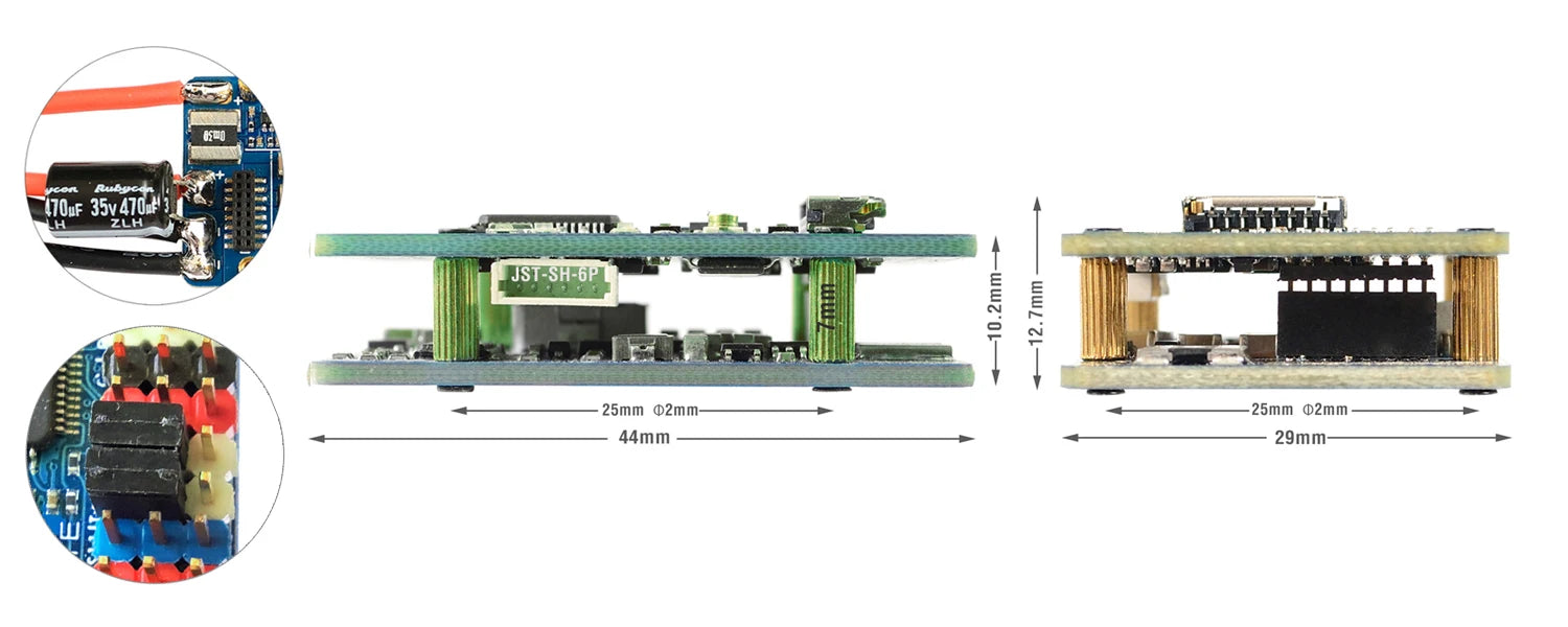
Mounting: 25 x 25mm, Φ2mm
-
Dimensions: 44 x 29 x 12.7mm
-
Weight: 22g w/ USB/buzzer adapter
Including
-
1x F405-WTE
-
1x USB(Type-C)/Beep (Passive buzzer) Extender + 20cm JST-SH-6P to JST-SH-6P cable for USB extender.
-
2x IPEX-MHF1 2.4G Antennas
-
1x Rubycon ZLH 35V 470uF capacitor
-
Dupont 2.54 pins (Board is shipped unsoldered)
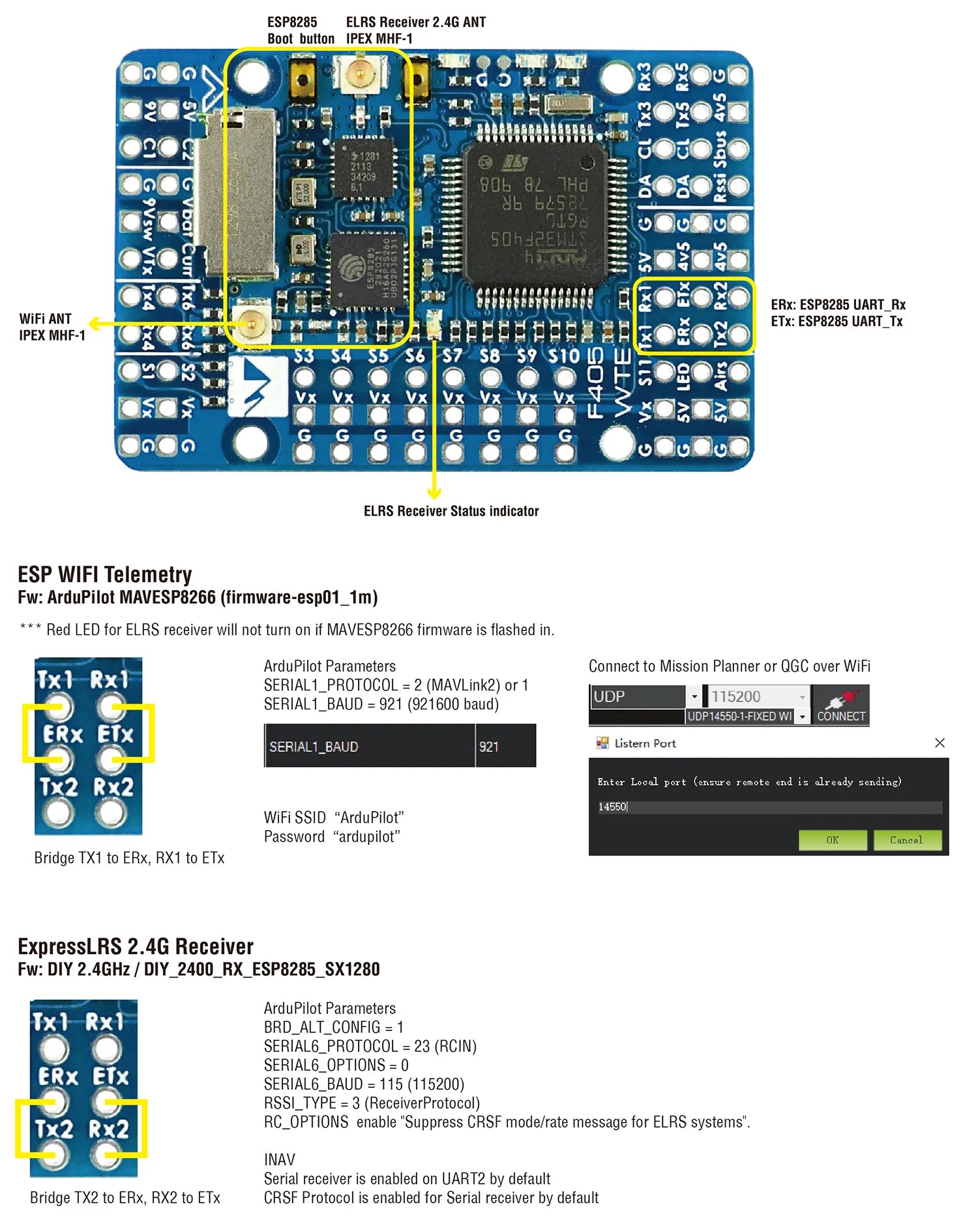
ArduPilot ESP8266 wifi telemetry
-
https://ardupilot.org/copter/docs/common-esp8266-telemetry.html
-
Firmware: firmware-esp01_1m.bin
-
Flashing with ESP_NodeMCU-PyFlasher
-
Wire the ESP8285(ETx, ERx) into the USB-TTL adapter, with ETx on F405-WTE connected to the Rx on the USB-TTL, and ERx connected to the Tx of the USB-TTL. Wire 4v5 and GND of F405-WTE to 5V and GND of the USB-TTL
-
Connect USB-TTL Adapter to PC while pressing and holding the ESP8285 boot button in.
-
open ESP_NodeMCU-PyFlasher
-
select Serial port of USB-TTL module, load firmware, select “Dual Output(DOUT)” and “Yes.wipes all data“
-
click “Flash NodeMCU“
-
after flashing, Power off , then power on F405-WTE by USB or Battery.
-
Wait a few seconds, search WiFi SSID “ArduPilot”, and password is “ardupilot”
-
Tips: Red LED for ELRS receiver will not turn on if MAVESP8266 firmware is flashed in.
-
ExpressLRS 2.4G Receiver
-
ExpressLRS AUX1-AUX8 are not full resolution CH. https://www.expresslrs.org/2.0/software/switch-config/
-
Flashing via WiFi
-
Power on F405-WTE by USB, Receiver’s LED(Red) will blink slow at first, and after 30s, it should blink fast indicating it’s on WiFi Hotspot Mode.
-
More detailed steps, pls refer this page.
-
Target: DIY 2.4GHz / DIY_2400_RX_ESP8285_SX1280
-
-
Flashing via UART
-
Wire the ESP8285(ETx, ERx) into the USB-TTL adapter, with ETx on F405-WTE connected to the Rx on the USB-TTL, and ERx connected to the Tx of the USB-TTL. Wire 4v5 and GND of F405-WTE to 5V and GND of the USB-TTL.
-
Connect USB-TTL Adapter to PC while pressing and holding the ESP8285 boot button in.
-
Select the target DIY 2.4GHz / DIY_2400_RX_ESP8285_SX1280 and “UART” for Flashing Method, set your bind phrase and Firmware Options and once done, click on Build and Flash.
-
UDP Connection with INAV configurator over WiFi
-
Firmware: MSPWifiBridge_ESP-01.bin compiled based on github.com/Scavanger/MSPWifiBridge
-
Flashing with ESP_NodeMCU-PyFlasher
-
Wire the ESP8285(ETx, ERx) into the USB-TTL adapter, with ETx on F405-WTE connected to the Rx on the USB-TTL, and ERx connected to the Tx of the USB-TTL. Wire 4v5 and GND of F405-WTE to 5V and GND of the USB-TTL
-
Connect USB-TTL Adapter to PC while pressing and holding the ESP8285 boot button in.
-
open ESP_NodeMCU-PyFlasher
-
select Serial port of USB-TTL module, load firmware, select “Dual Output(DOUT)” and “Yes.wipes all data“
-
click “Flash NodeMCU“
-
after flashing, Power off , then power on F405-WTE by USB or Battery.
-
Wait a few seconds, search WiFi SSID “MSPWifiBridge”, and password is “123456789”
-
If there is no automatic forwarding to the configuration page, go to http://192.168.4.1 manually. Standard login data: Username: admin, Password: 123456789
-
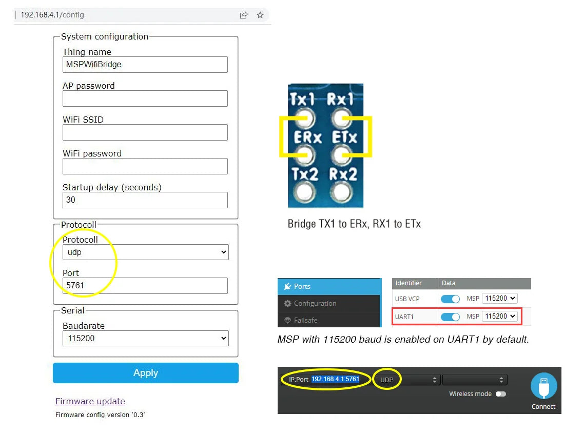
192.168.4.1/config System configuration Thing_name MSPWifiBridge AP password Ixl Rx| WiFi SSID ERx ETx WiFi password Tx2 Rx2 Staz delay (seconds 30 Protocoll Bridge TX1 to erx, RXI to ETx Protocoll udp Port 5761 Ponts Identifier Data USB VC?

Drone Categories
-
All Drones
All Drones This includes a wide variety of drone The...
-
Mini Drone
The characteristics of mini drones are small size, light weight, portable, short...
-
Camera Drone
Camera Drone is very suitable for photography enthusiasts, basically equipped with 3-axis...
-
Agriculture Drone
What is Agriculture Drone? Agriculture drones, also known as precision agriculture drones...
-
Rc Helicopter
RC helicopters, also known as remote-controlled helicopters, are miniature aircraft that are...
-
Drone Battery
Drone Battery, the most common batteries used in drones are lithium polymer (LiPo)...
-
Drone Motor
Drone Motors, FPV Motors,Airplane Motors,Helicopter Motors, Car Motors. Drone motors are classified...
-
Drone Propeller
Drone Propeller: A drone propeller is a rotating component that generates thrust...
-
Drone Remote Controller
Drone Remote Controller, Transmitter When choosing a remote controller for a drone,...
-
Drone Transmitter & Receiver
Drone Transmitter & Drone Receiver FPV Transmitter & FPV Receiver Drone Transmitter and...
-
Accessories
Drone Accessories Quadcopter Frame. This is a structure (frame) in which all...