طقم سيرفو ذكي Yahboom YB-SD35M 35KG·CM مع لوحة تصحيح السائق للذراع الروبوتية UART
طقم سيرفو ذكي Yahboom YB-SD35M 35KG·CM مع لوحة تصحيح السائق للذراع الروبوتية UART
Yahboom
تعذر تحميل توفر الالتقاط
نظرة عامة
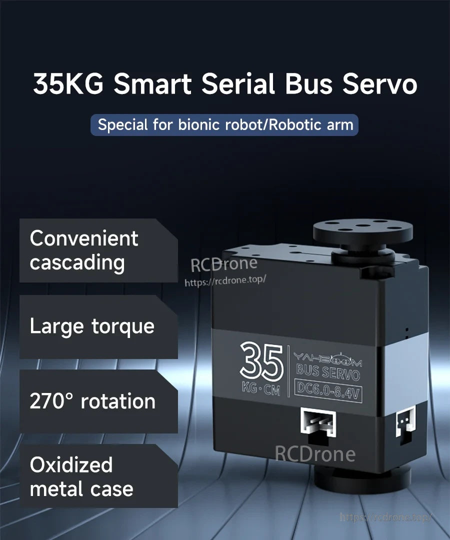
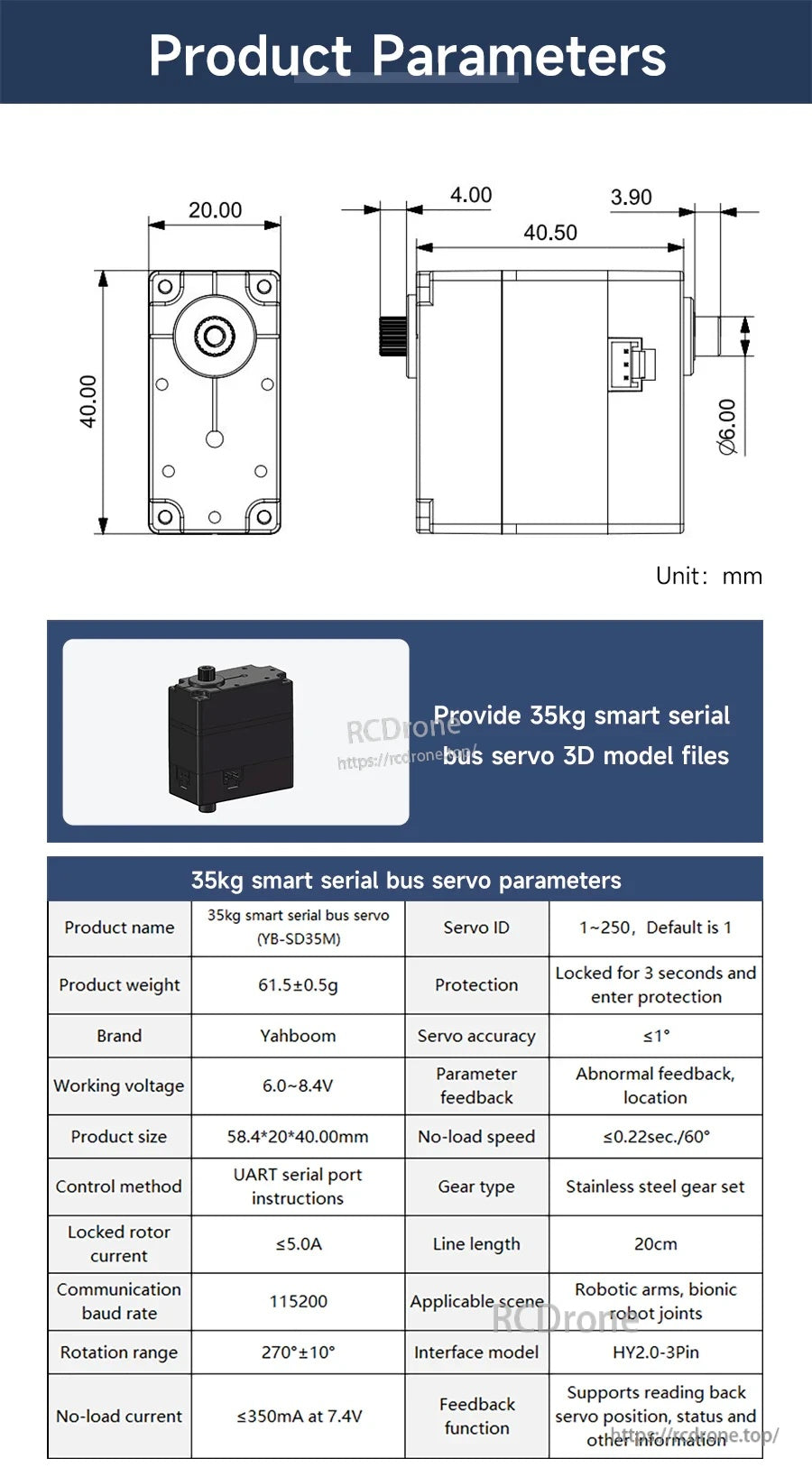
تتضمن مجموعة السيرفو الذكي بالحافلة التسلسلية سيرفو ياهبوم 35 كجم الذكي بالحافلة التسلسلية (YB-SD35M) ولوحة تصحيح للسائق للتحكم عبر الكمبيوتر الشخصي ووحدة التحكم الدقيقة في تطبيقات الذراع الروبوتية ومفاصل الروبوت الحيوية. يدعم السيرفو التوصيل المتسلسل المريح على حافلة واحدة، وعزم دوران كبير 35 كجم·سم، ونطاق دوران واسع (0–270°، المواصفات: 270° ±10°). يستخدم مقياس جهد عالي الدقة لتغذية زاوية الارتجاع، بالإضافة إلى تروس ومحامل من الفولاذ المقاوم للصدأ للمتانة. توفر ثلاث واجهات HY2.0-3Pin (يسار/أعلى/يمين) توصيلات مرنة من اتجاهات متعددة.
الميزات الرئيسية
- التوصيل المتسلسل بالحافلة التسلسلية: يمكن توصيل عدة سيرفو في سلسلة عبر واجهة مضادة للعكس لتقليل تعقيد الأسلاك.
- عزم دوران 35 كجم·سم و دوران 270° (المواصفات: 270° ±10°).
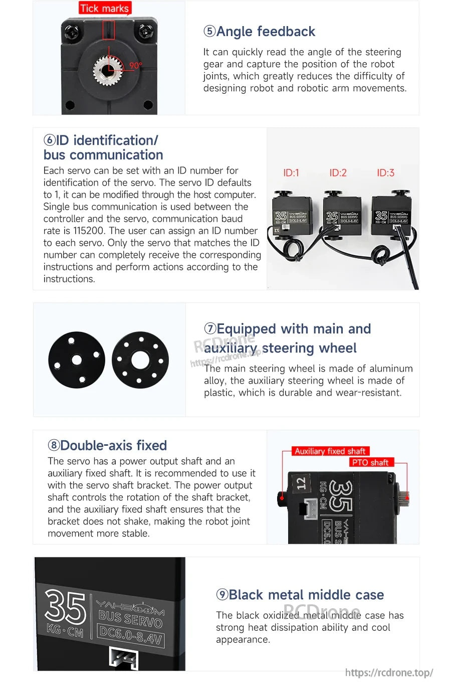
- ردود فعل الزاوية: يقرأ زاوية التوجيه / موضع المفصل لتقليل صعوبة تصميم حركة الروبوت وذراع الروبوت.
- تحديد الهوية ID & اتصال الحافلة : نطاق معرف السيرفو 1–250 (الافتراضي 1)؛ معدل نقل البيانات 115200.
- برنامج تصحيح السيرفو على الكمبيوتر الشخصي: يدعم إعداد معرف السيرفو، سرعة الدوران، انحراف الموضع، إلخ. (مصمم للاستخدام مع لوحة تصحيح السائق من Yahboom).
- ثلاث واجهات سيرفو متوازية على لوحة السائق: واجهات 3-pin HY2.0 تساعد في منع الاتصالات العكسية.
- الهيكل الميكانيكي: مجموعة محامل من الفولاذ المقاوم للصدأ ومجموعة تروس من الفولاذ المقاوم للصدأ؛ علبة معدنية سوداء مؤكسدة لتبديد الحرارة.
- تثبيت مزدوج المحور: عمود إخراج الطاقة بالإضافة إلى عمود ثابت مساعد؛ يشمل عجلات توجيه رئيسية (سبائك الألومنيوم) ومساعدة (بلاستيك).
- موارد التعليمات البرمجية متعددة المنصات متوفرة لـ Raspberry Pi، Jetson Nano، Arduino (UNO)، micro:bit، STM32 MCU، 51 MCU، و K210.
- يوفر ملفات نماذج ثلاثية الأبعاد لسيرفو ذكي بوزن 35 كجم.
للدعم في التوصيل والإعداد، اتصل بـ https://rcdrone.top/ أو أرسل بريدًا إلكترونيًا إلى [email protected].
المواصفات
سيرفو ذكي بوزن 35 كجم (YB-SD35M)
| اسم المنتج | سيرفو ذكي بوزن 35 كجم (YB-SD35M) |
| العلامة التجارية | Yahboom |
| عزم الدوران | 35 كجم·سم |
| جهد التشغيل | 6.0–8.4 فولت (التسمية: DC6.0–8.<|vq_15392|>4V) |
| نطاق الدوران | 270° ±10° |
| دقة السيرفو | ≤ 1° |
| طريقة التحكم | تعليمات منفذ تسلسلي UART |
| معدل نقل البيانات | 115200 |
| معرف السيرفو | 1–250 (الافتراضي 1) |
| الحماية | مغلق لمدة 3 ثوانٍ ويدخل في وضع الحماية |
| سرعة بدون حمل | ≤ 0.22 ثانية/60° |
| تيار بدون حمل | ≤ 350 مللي أمبير عند 7.4 فولت |
| تيار الدوار المقفل | ≤ 5.0 A |
| نوع التروس | مجموعة تروس من الفولاذ المقاوم للصدأ |
| وظيفة التغذية الراجعة | يدعم قراءة موضع السيرفو، الحالة والمعلومات الأخرى |
| تغذية راجعة للمعلمات | تغذية راجعة غير طبيعية، الموقع |
| نموذج الواجهة | HY2.0-3Pin |
| طول الخط | 20 سم |
| حجم المنتج | 58.4 × 20 × 40.00 مم |
| وزن المنتج | 61.5 ±0.5 جم |
| المشهد المناسب | الأذرع الروبوتية، مفاصل الروبوتات البيونيكية |
| ملاحظات الرسم الميكانيكي (الوحدة: مم) | 20.00; 40.00; 40.50; 4.00; 3.90; قطر العمود φ6.00 |
لوحة تصحيح السائق
| مدخل جهد واسع | 7.4–12.6 V |
| جهد خرج واجهة السيرفو | 6.3 فولت (+0.2) |
| تيار خرج واجهة السيرفو | 1.2 أمبير (الحد الأقصى: 2 أمبير) |
| واجهة USB | microUSB |
| تباعد رأس الدبوس | 2.54 |
| الحجم | 50 مم × 35 مم × 12.5 mm |
| مسافة ثقوب التثبيت | 30 مم |
| قطر ثقوب التثبيت | 3 مم |
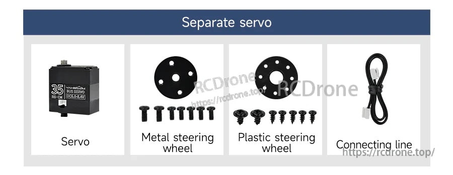
ما هو متضمن
- حزمة سيرفو منفصلة: سيرفو، عجلة قيادة معدنية، عجلة قيادة بلاستيكية، خط توصيل، براغي تثبيت
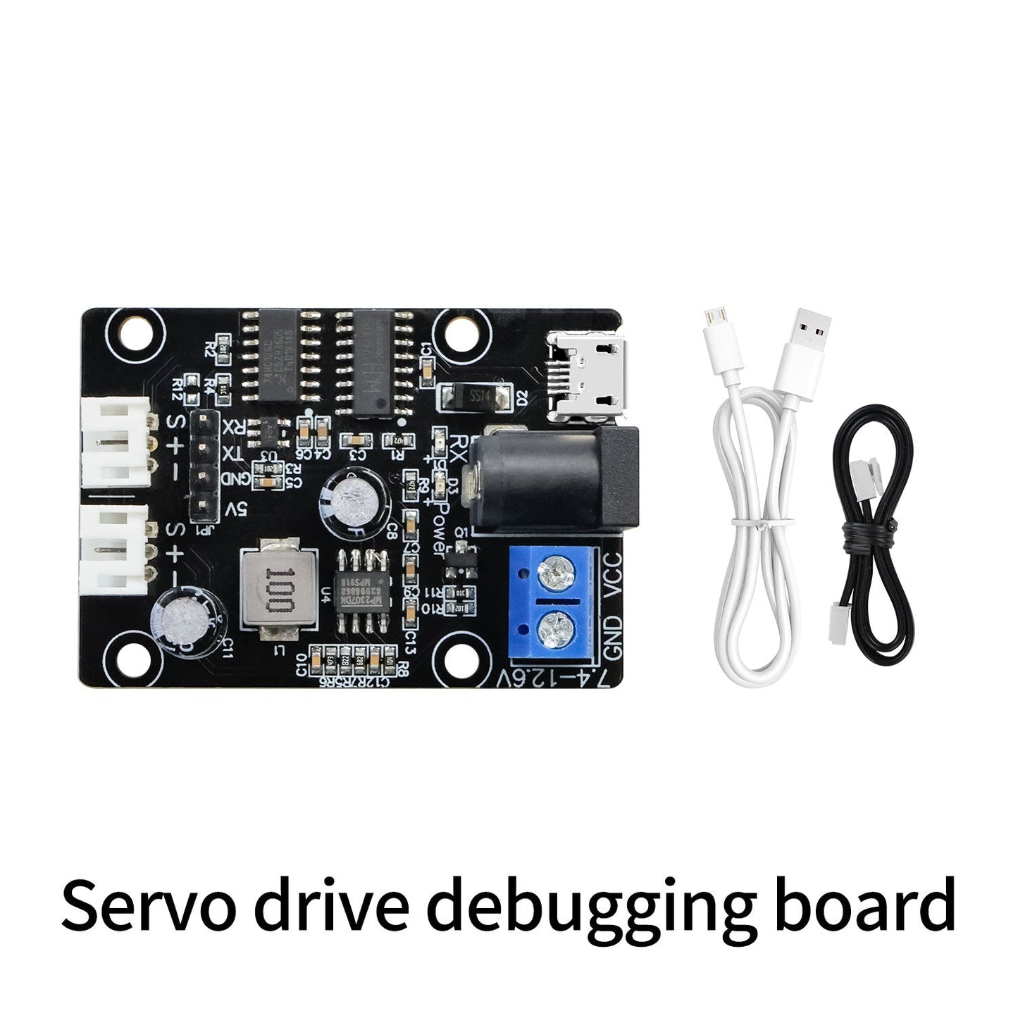
- حزمة لوحة تصحيح قيادة السيرفو: لوحة تصحيح قيادة السيرفو، كابل بيانات (microUSB)، خط توصيل
التطبيقات
- أذرع روبوتية وتحكم في الوصلات متعددة المفاصل
- مفاصل الروبوتات البيونيكية
- أنظمة الأتمتة التي تتطلب تسلسل سيرفو بالحافلة
الأدلة / الشروحات
التفاصيل
سيرفو ذكي تسلسلي عالي العزم مصمم للأذرع الروبوتية ومفاصل الروبوتات البيونيكية، مع تسلسل حافلة مريح.

تساعد موارد التعليمات البرمجية متعددة المنصات في التحكم في السيرفو من SBCs وMCUs الشهيرة أثناء النمذجة والتكامل.
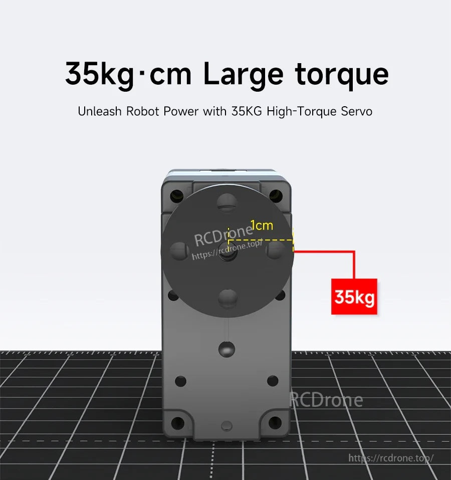
عزم الدوران المقدر 35kg·cm يدعم روابط الروبوت الأثقل وتصميمات المفاصل ذات الحمل العالي.
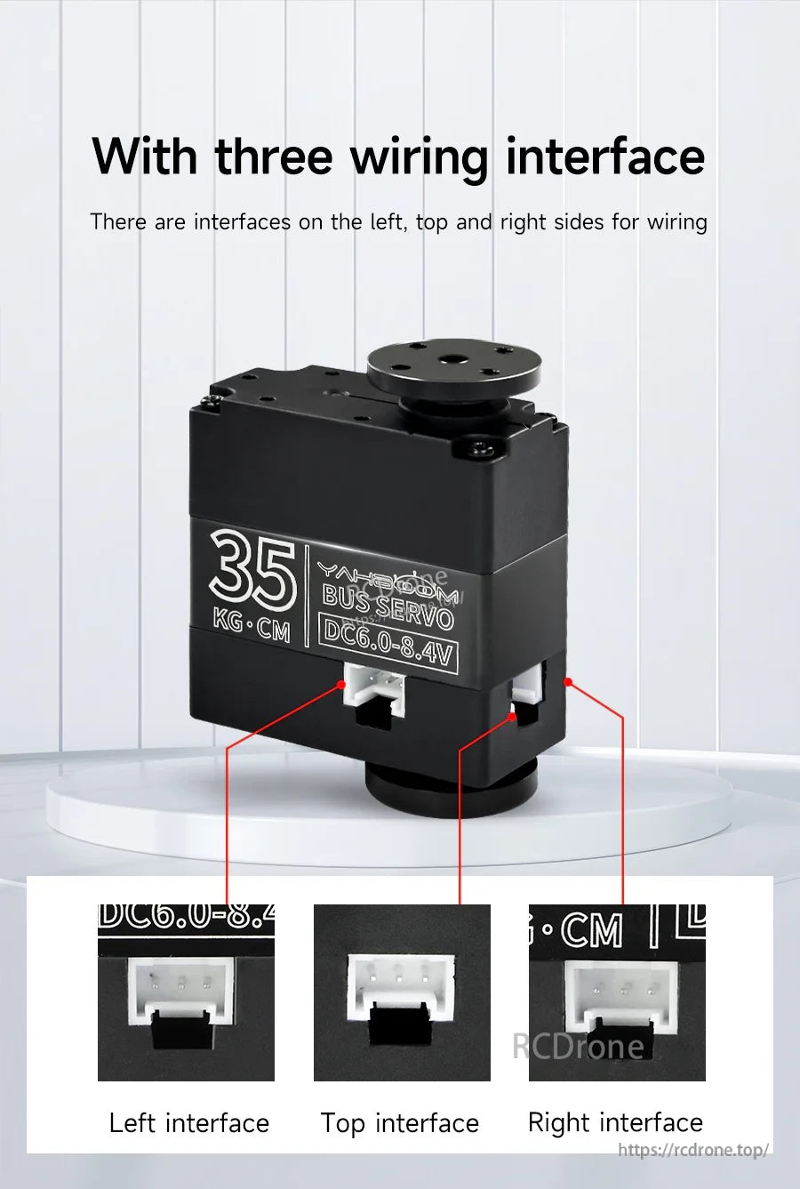
تجعل منافذ HY2.0-3Pin ذات الاتجاه الثلاثي توجيه الكابلات أسهل في الإطارات الضيقة والتجميعات متعددة المفاصل.
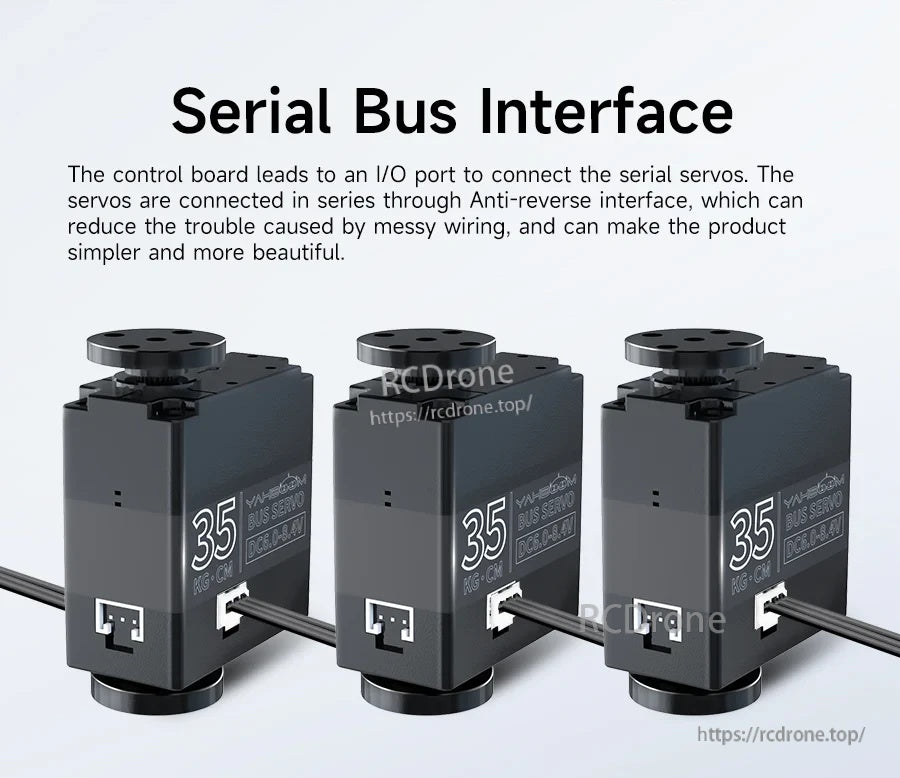
قم بتوصيل عدة سيرفو على ناقل واحد لتبسيط الأسلاك وتوسيع التحكم في المفاصل المتعددة.

تحسين الثبات في تحديد المواقع والموثوقية طويلة الأمد بفضل التغذية الراجعة الداخلية ومكونات نظام القيادة المعدني المتين.
تتيح التغذية الراجعة للزاوية بالإضافة إلى الاتصال المعتمد على الهوية لكل مفصل أن يتم توجيهه ومراقبته عبر نفس الناقل التسلسلي.
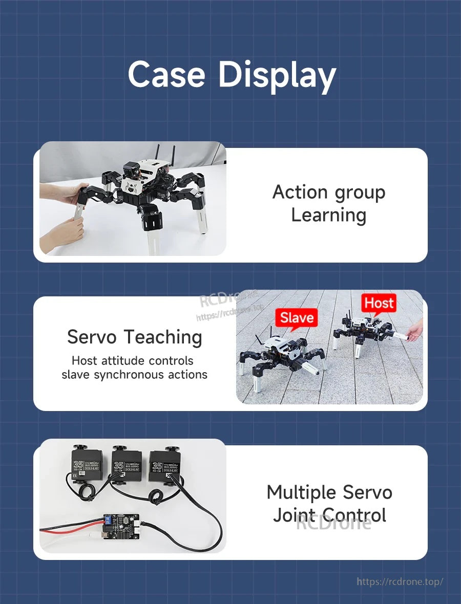
تدعم أوضاع التحكم المفيدة تعلم الحركة المنسقة، والتعليم، وتزامن السيرفو المتعدد.

يبسط برنامج الكمبيوتر الشخصي الإعداد - ضبط معلمات الهوية والسرعة والموقع قبل النشر إلى وحدة التحكم الخاصة بك.
تساعد الأبعاد والمواصفات الرئيسية في التخطيط الميكانيكي، وتسرع الملفات ثلاثية الأبعاد من تكامل CAD.
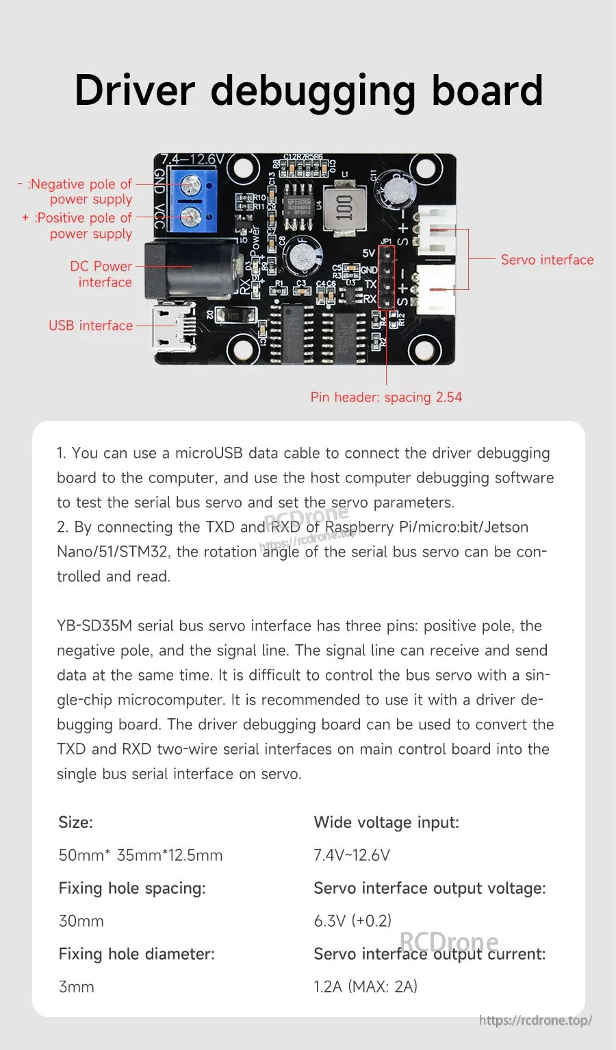
استخدم لوحة تصحيح الأخطاء للسائق لتوصيل السيرفو بجهاز كمبيوتر أو وحدة تحكم دقيقة للتكوين والاختبار.
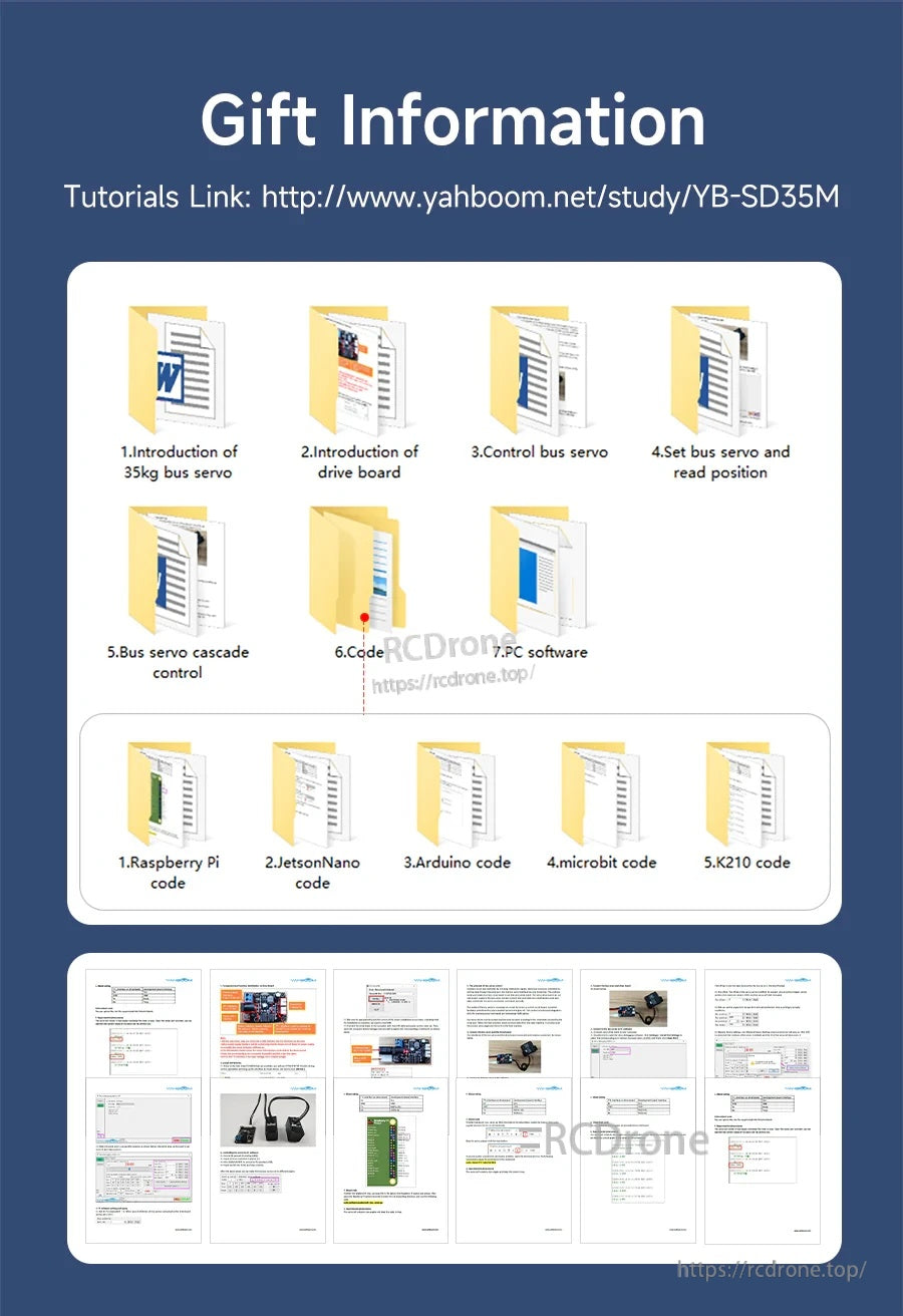
تغطي الوثائق والمشاريع النموذجية الأسلاك والتحكم المتسلسل والرموز لعدة منصات شائعة.


Related Collections